

VPR220SZ (Z-Foil)
Vishay Foil Resistors
Ultra High Precision Z-Foil Surface Mount Power Resistors in
TO-220 Configuration with TCR of ± 0.05 ppm/°C,
Tolerance to ± 0.01 % and Power Rating to 8 W
Any value at any tolerance available within resistance range
Model VPR220SZ, made from Vishay Bulk Metal® Z-Foil,
offers very low TCR, high stability, tight tolerance, low PCR
and fast response time in a small surface mount molded
resistor.
The Z-Foil technology provides a significant reduction of the
resistive components sensitivity to ambient temperature
variations and applied power changes. Designers now can
guarantee a high degree of stability and accuracy in fixed
resistor applications using solutions based on Vishay’s
revolutionary Z-Foil technology.
Our Application Engineering Department is available to
advise and make recommendations. For non-standard
technical requirements and special applications, please
contact us.
FEATURES
•
Temperature Coefficient of Resistance (TCR):
± 0.05 ppm/°C typical (0 °C to + 60 °C)
± 0.2 ppm/°C typical (- 55 °C to + 125 °C,
- 25 °C Ref.)
• Tolerance: to ± 0.01 %
• Power Coefficient of Resistance (PCR) “ΔR
due to self heating”: 5 ppm at rated power
• Electrostatic Discharge (ESD) above 25 000 V
• Load Life Stability: ± 0.005 % (25 °C, 2000 hours at Rated
Power)
• Resistance Range: 5 Ω to 10 kΩ
• Power Rating: 8 W chassis mounted (per MIL-PRF-39009)
• Non Inductive, Non Capacitive Design
• Current Noise: < - 40 dB
• Voltage Coefficient: < 0.1 ppm/W
• Non Inductive: < 0.08 µH
• Non Hot Spot Design
• Thermal EMF: 0.05 µV/°C typical
• Terminal Finishes Available: Lead (Pb)-free
Tin/Lead Alloy
•
For higher performances please contact us
Pb-free
Available
RoHS*
COMPLIANT
TABLE 1 - SPECIFICATIONS
Load Life Stability at 2000 h
Power Rating at + 25 °C
Current Noise
High Frequency Operation
Rise Time
Inductance3) (L)
Capacitance (C)
Voltage Coefficient
Operating Temperature
Range
Maximum Working Voltage
Thermal EMF
4)
5)
± 0.05 % max ΔR under full rated
power at + 25 °C
8 W or 3 A1) on heat sink
1.5 Wor 3 A1) in free air
Further derating not necessary.
< 0.010 µV (rms)/V of applied
voltage (- 40 dB)
1 ns
0.1 µH maximum: 0.03 µH typical
1.0 pF maximum: 0.5 pF typical
< 0.1 ppm/V
- 55 °C to + 150 °C
300 V. Not to exceed power rating.
0.15 µV/°C maximum (lead effect)
2)
Notes
1. Whichever is lower.
2. Heat sink chassis dimensions and requirements per
MIL-PRF-39009:
DIMENSION
L 6.00 152.4
W 4.00 101.6
H 2.00 50.8
T 0.04 1.0
3. Inductance (L) due mainly to the leads.
4. The resolution limit of existing test equipment (within the
measurement capability of the equipment, or “essentially zero”).
5. µV/°C relates to EMF due to lead temperature difference.
INCHES mm
TABLE 2 - VPR220SZ
1)
RESISTANCE RANGE (Ω) TIGHTEST RESISTANCE TOLERANCE
50 to 10K ± 0.01 %
25 to < 50 ± 0.02 %
10 to < 25 ± 0.05 %
5 to < 10 ± 0.1 %
Weight = 1 g Maximum
Note
1. Maximum specifications.
* Pb containing terminations are not RoHS compliant, exemptions may apply
www.vishay.com For any questions, contact: foil@vishay.com
1 Revision: 06-Aug-07
- 55 °C to + 125 °C, Ref. + 25 °C
TCR
± 2.5 ppm/°C
Document Number: 63068
VPR220SZ (Z-Foil)
k
Ultra High Precision Z-Foil Surface Mount Power Resistors
in TO-220 Configuration with TCR of ± 0.05 ppm/°C,
Tolerance to ± 0.01 % and Power Rating to 8 W
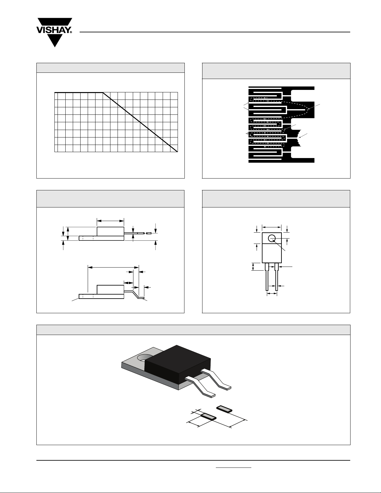
FIGURE 1 - POWER DERATING CURVE
- 55 °C
+ 100
+ 75
+ 50
+ 25
Percent of Rated Power
0
Ambient Temperature (°C)
FIGURE 3 - VPR220SZ FORMING
0.050 ± 0.005
(1.27 ± 0.13)
Heat Sink
DIMENSIONS
0.365 (9.27) Ref
0.150 ± 0.008
(3.81 ± 0.20)
Before Forming
After Forming
0.695 ± 0.010
(17.65 ± 0.25)
0.090 (2.286) Ref
in inches (millimeters)
0.015 ± 0.002
(0.38 ± 0.05)
0.078 ± 0.005
(1.98 ± 0.13)
0.110 (2.79) Ref
0.090 ± 0.010
(2.29 ± 0.25)
Flush with Heat Sin
Within ±0.002 (± 0.05)
Vishay Foil Resistors
FIGURE 2 - TRIMMING TO VALUES
(Conceptual Illustration)
Interloop Capacitance
Reduction in Series
Current Path
Mutual Inductance
Reduction due
to Change in
Current Direction
+ 150+ 125+ 100+ 75+ 50+ 250- 25- 50
Note: Foil shown in black, etched spaces in white
After Trimming
FIGURE 4 - VPR220SZ DIMENSIONS
in inches (millimeters)
0.400 ± 0.010
(10.16 ± 0.25)
0.245 ± 0.010
(6.22 ± 0.25)
0.200 ± 0.030
(5.08 ± 0.76)
VISHAY
VPR220SZ
1K0 1 %
0101
0.200 ± 0.005
(5.08 ± 0.13)
0.115 ± 0.005
(2.92 ± 0.13)
0.141 ± 0.005 Diameter
(3.58 ± 0.13)
0.050 ± 0.005
(1.27 ± 0.13)
0.030 ± 0.002
(0.76 ± 0.05)
Current Path
Before Trimming
Trimming Process
Removes this Material
from Shorting Strip Area
Changing Current Path
and Increasing
Resistance
FIGURE 5 - LAND PATTERN DIMENSIONS in inches (millimeters)
0.050 ± 0.010
(1.27 ± 0.25)
0.120 ± 0.010
(3.05 ± 0.25)
Document Number: 63068 For any questions, contact: foil@vishay.com
Revision: 06-Aug-07 2
0.200 ± 0.005
(5.08 ± 0.13)
www.vishay.com

VPR220SZ (Z-Foil)
Vishay Foil Resistors
Ultra High Precision Z-Foil Surface Mount Power Resistors
in TO-220 Configuration with TCR of ± 0.05 ppm/°C,
Tolerance to ± 0.01 % and Power Rating to 8 W
TABLE 3 - GLOBAL PART NUMBER INFORMATION
NEW GLOBAL PART NUMBER: Y16235R00000Q9L (preferred part number format)
DENOTES PRECISION VALUE AER*
YR = Ω
6235 000RY1 Q90 L0
PRODUCT CODE RESISTANCE TOLERANCE PACKAGING
1623 = VPR220SZ T = ± 0.01 %
FOR EXAMPLE: ABOVE GLOBAL ORDER Y1623 5R00000 Q 9 L:
TYPE: VPR220SZ
VALUE: 5.0 Ω
ABSOLUTE TOLERANCE: ± 0.02 %
TERMINATION: Lead (Pb)-free
PACKAGING: Bulk
HISTORICAL PART NUMBER: VPR220SZT 5R0000 Q B (will continue to be used)
VPR220SZ T 5R0000 Q B
MODEL TERMINATION OHMIC VALUE
VPR220SZ T = Lead (Pb)-free
None = Tin/Lead alloy
K = kΩ
Q = ± 0.02 %
A = ± 0.05 %
B = ± 0.1 %
C = ± 0.25 %
D = ± 0.5 %
F = ± 1.0 %
G = ± 2.0 %
J = ± 5.0 %
5.0 Ω T = ± 0.01 %
RESISTANCE
TOLERANCE
Q = ± 0.02 %
A = ± 0.05 %
B = ± 0.1 %
C = ± 0.25 %
D = ± 0.5 %
F = ± 1.0 %
G = ± 2.0 %
J = ± 5.0 %
0 = Standard
9 = Lead (Pb)-free
1 - 999 = Custom
L = Bulk Pack
R = Tape and Reel
PA CK A GI N G
B = Bulk
T = Tape and Reel
Note
* For non-standard requests, please contact Application Engineering.
www.vishay.com For any questions, contact: foil@vishay.com Document Number: 63068
3 Revision: 06-Aug-07

Legal Disclaimer Notice
Vishay
Disclaimer
All product specifications and data are subject to change without notice.
Vishay Intertechnology, Inc., its affiliates, agents, and employees, and all persons acting on its or their behalf
(collectively, “Vishay”), disclaim any and all liability for any errors, inaccuracies or incompleteness contained herein
or in any other disclosure relating to any product.
Vishay disclaims any and all liability arising out of the use or application of any product described herein or of any
information provided herein to the maximum extent permitted by law. The product specifications do not expand or
otherwise modify Vishay’s terms and conditions of purchase, including but not limited to the warranty expressed
therein, which apply to these products.
No license, express or implied, by estoppel or otherwise, to any intellectual property rights is granted by this
document or by any conduct of Vishay.
The products shown herein are not designed for use in medical, life-saving, or life-sustaining applications unless
otherwise expressly indicated. Customers using or selling Vishay products not expressly indicated for use in such
applications do so entirely at their own risk and agree to fully indemnify Vishay for any damages arising or resulting
from such use or sale. Please contact authorized Vishay personnel to obtain written terms and conditions regarding
products designed for such applications.
Product names and markings noted herein may be trademarks of their respective owners.
Document Number: 91000 www.vishay.com
Revision: 18-Jul-08 1
 Loading...