

Page 1
Features
• Low power dissipation class A
amp: 6.5W with 25 MHz (clock)
• Bandwidth f (–3 dB) = 70 MHz
• Pulse response (tr, tf)
tr = 5.8 ns (typ) and tf = 5.0 ns (typ)
at 40 Vp-p swing
• Plastic mold package for excellent reliability
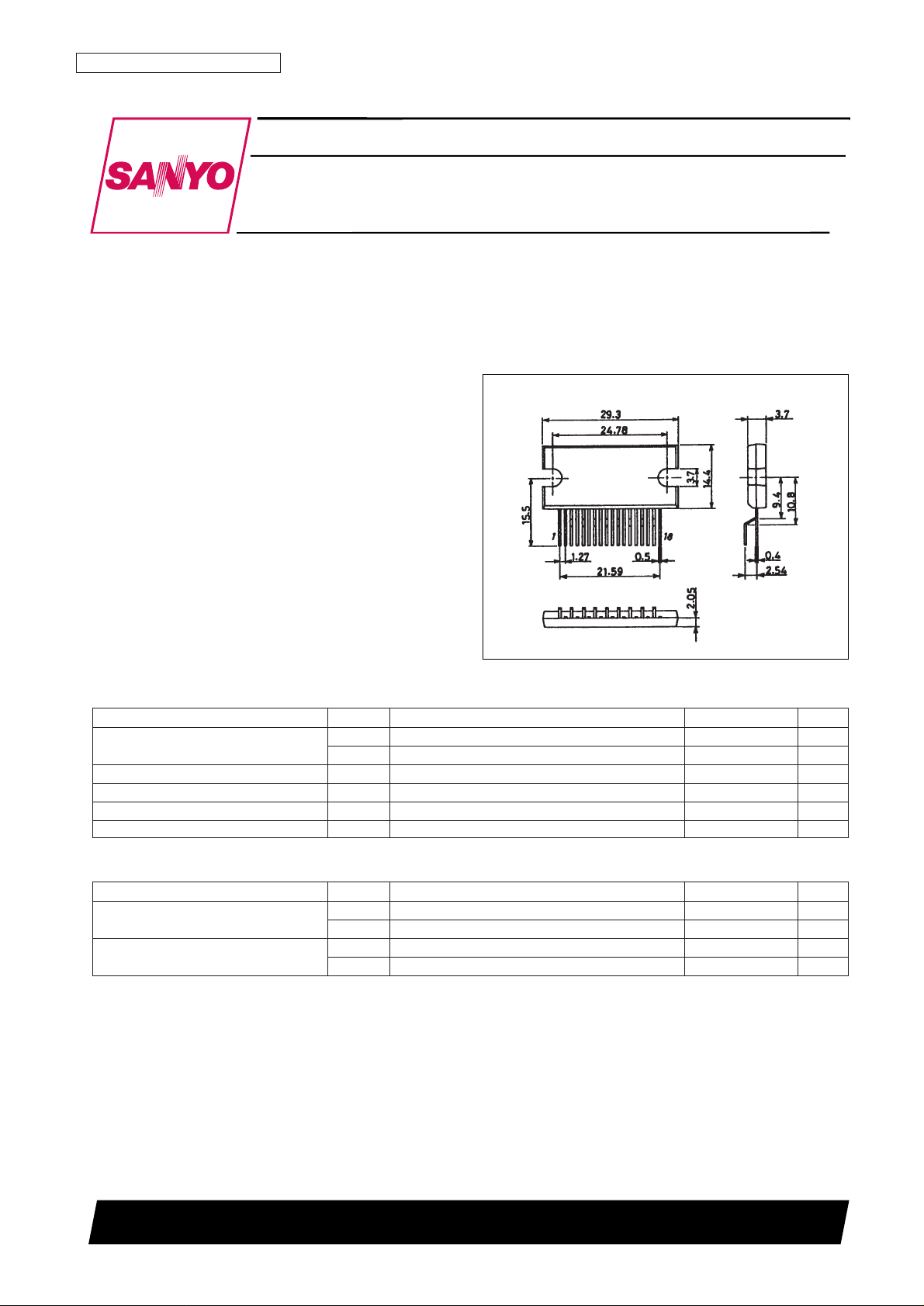
Package Dimensions
unit: mm
2117
Wideband Output Module (video pack)
53096HA (OT) No. 5331-1/8
[VP513]
SANYO Electric Co.,Ltd. Semiconductor Bussiness Headquarters
TOKYO OFFICE Tokyo Bldg., 1-10, 1 Chome, Ueno, Taito-ku, TOKYO, 110 JAPAN
CRT Display Video Output Amplifier:
High-Voltage, Wideband Amplification
VP513
Ordering number : EN5331
Specifications
Absolute Maximum Ratings at Ta = 25°C
Parameter Symbol Conditions Ratings Unit
Maximum supply voltage
V
CC
max 90 V
V
BB
max 15 V
Allowable power dissipation Pd max At Tc = 25°C with an ideal heat sink 25 W
Junction temperature Tj max 150 °C
Case temperature Tc max 100 °C
Storage temperature Tstg –20 to +110 °C
Operating Conditions at Ta = 25°C
Parameter Symbol Conditions Ratings Unit
Recommended supply voltage I
V
CC
70 V
V
BB
10 V
Recommended supply voltage II
V
CC
80 V
V
BB
10 V
Page 2
No. 5331-2/8
VP513
Parameter Symbol Conditions
Ratings
Unit
min typ max
Bandwidth I (–3 dB) fc
V
CC
= 70 V, VBB= 10 V, CL= 5 pF, VIN(DC) = 2.6 V,
70 MHz
V
OUT
(p-p) = 40 V
Bandwidth II (–3 dB) fc
V
CC
= 80 V, VBB= 10 V, CL= 5 pF, VIN(DC) = 2.9 V,
65 MHz
V
OUT
(p-p) = 50 V
Pulse response characteristics
tr
V
CC
= 80 V, VBB= 10 V, CL= 5 pF, VIN(DC) = 2.9 V,
5.8 ns
tf
V
OUT
(p-p) = 40 V
5.0 ns
Voltage gain G
V
(DC) 13 15 17
I
CC
1
V
CC
= 70 V, VBB= 10 V, VIN(DC) = 2.6 V,
25 mA
Current drain I
f = 10 MHz clock, C
L
= 5 pF, V
OUT
(p-p) = 40 V
I
CC
2
V
CC
= 70 V, VBB= 10 V, VIN(DC) = 2.6 V,
40 mA
f = 70 MHz clock, C
L
= 5 pF, V
OUT
(p-p) = 40 V
I
CC
1
V
CC
= 80 V, VBB= 10 V, VIN(DC) = 2.9 V,
30 mA
Current drain II
f = 10 MHz clock, C
L
= 5 pF, V
OUT
(p-p) = 50 V
I
CC
2
V
CC
= 80 V, VBB= 10 V, VIN(DC) = 2.9 V,
47 mA
f = 70 MHz clock, C
L
= 5 pF, V
OUT
(p-p) = 50 V
Electrical Characteristics at Ta = 25°C
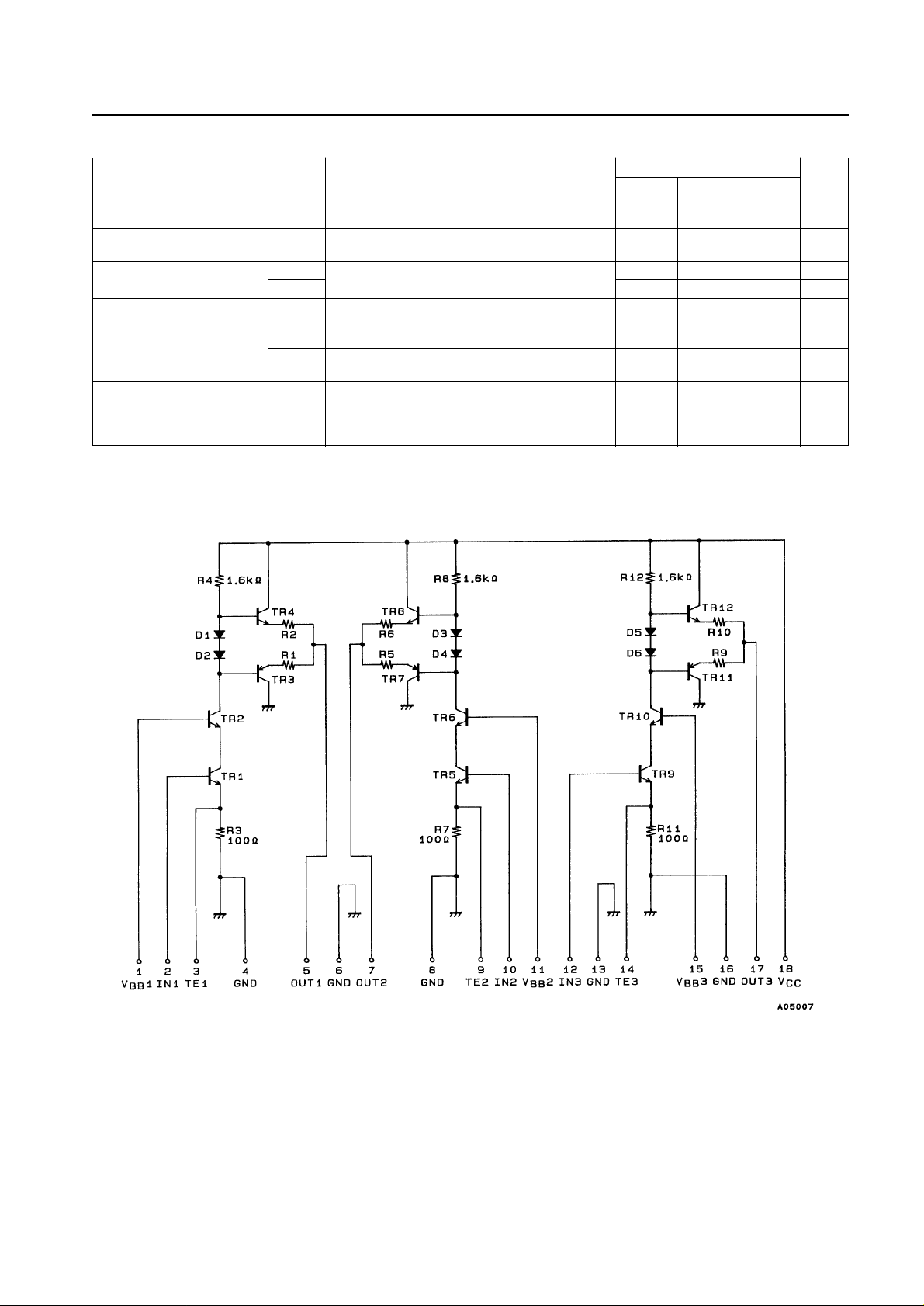
Internal Equivalent Circuit
Page 3
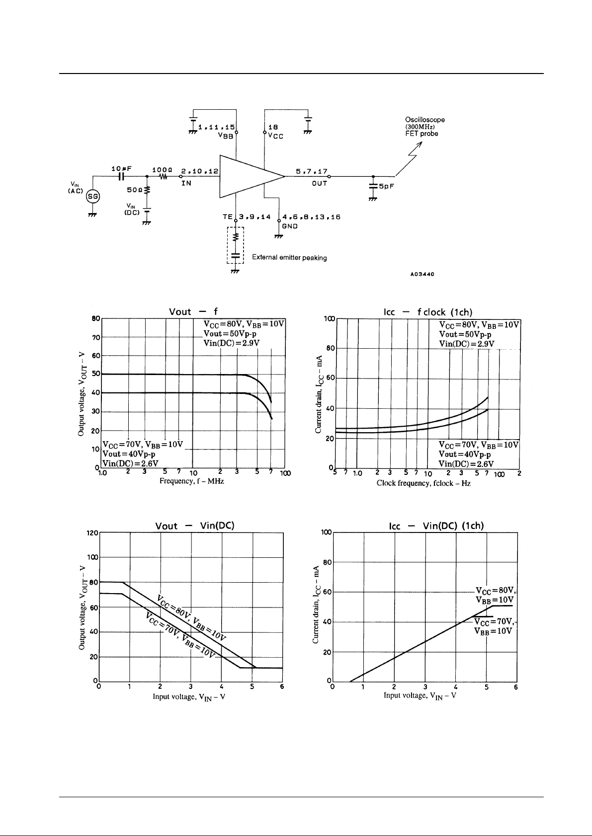
Test Circuit
No. 5331-3/8
VP513
Page 4
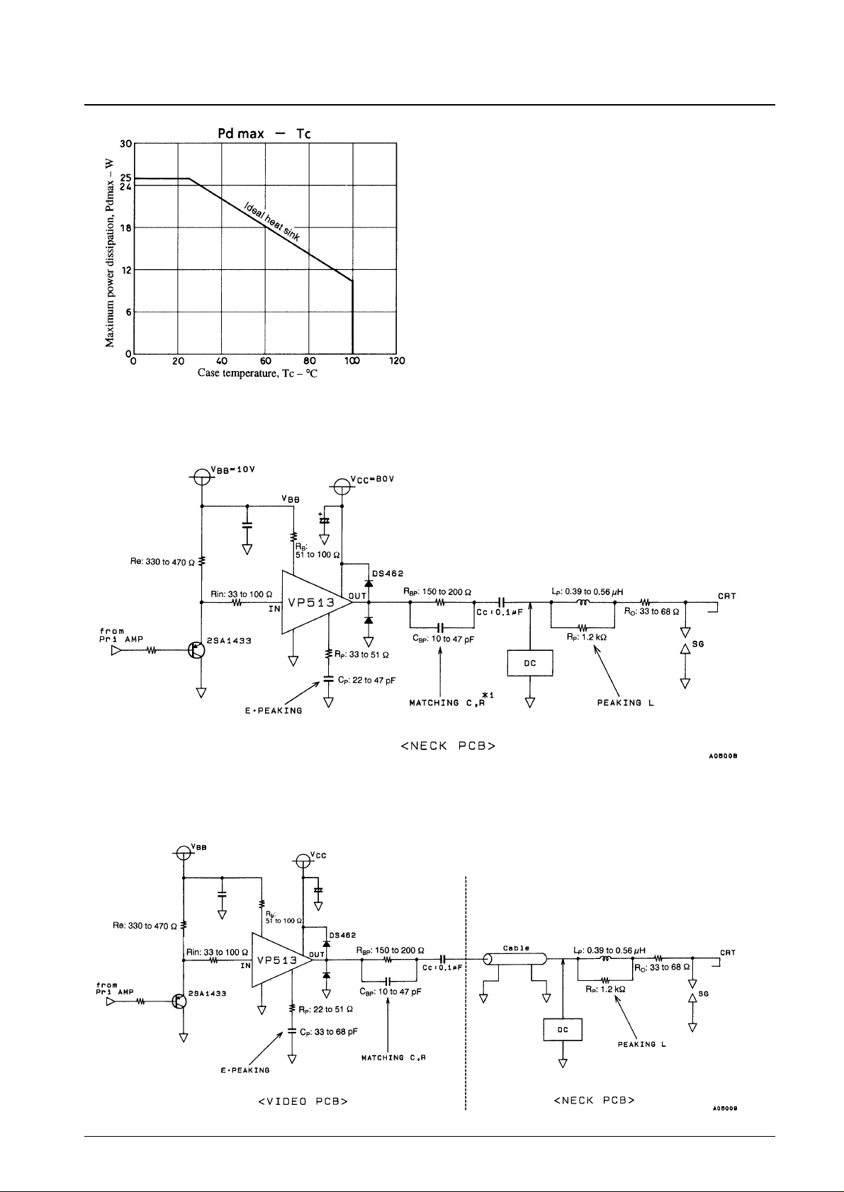
Application Circuit Examples
1. CRT neck mounted circuit
2. Cable transmission (separated boards)
Note: 1. The matching RC circuit is used to match the IC internal impedance with the impedance of the load. In neck mounted applications, this circuit can
be removed if the total load capacitance, C
L
, is no more than 10 pF.
No. 5331-4/8
VP513
Page 5
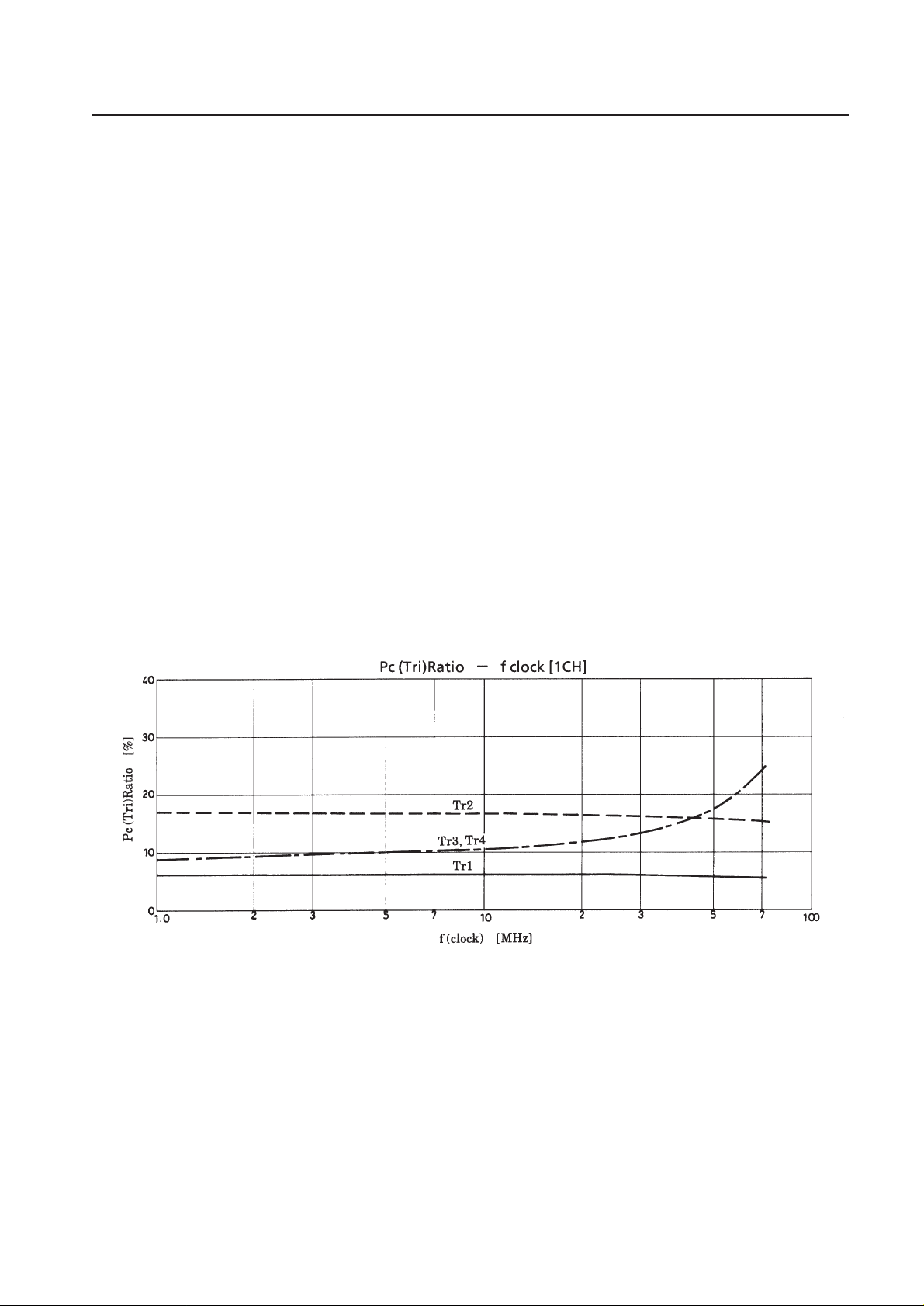
Thermal Design for the VP513
Since the VP513 includes three channels, we first consider a single channel. The chip temperature of each transistor
under actual operating conditions is determined using the following formula.
Tj = (Tri) = θj-c (Tri) × Pc (Tri) + ∆Tc + Ta [°C].................................. (1)
θj-c (Tri): Thermal resistance of an individual transistor
Pc (Tri): Collector loss for an individual transistor
∆Tc: Case temperature rise
Ta: Ambient temperature
The θj-c(Tri) for each chip is:
θj-c (Tr1) = 45°C/W/θj-c (Tr2) to (Tr4) = 35°C/W................................ (2)
Although the loss for each transistor in a Video Pack varies with frequency and is not uniform, if we assume that the
maximum operating frequency, f = 70 MHz (clock), then the chips with the largest loss will be transistors 3 and 4 (Tr3
and Tr4) and that loss will be about 1/4 of the total loss.Thus from the Pd for a single channel we have:
Pc (Tr3) 70 MHz = Pd (1CH) 70 MHz × 1/4.......................................... (3)
Here, we must select a heat sink with a capacity θh such that the Tj of these transistors does not exceed 150°C. Equation
(4) below gives the relationship between θh and ∆Tc.
∆Tc = Pd (TOTAL) × θh ........................................................................ (4)
The required θh is calculated using this equation and equation (1).
No. 5331-5/8
VP513
Page 6
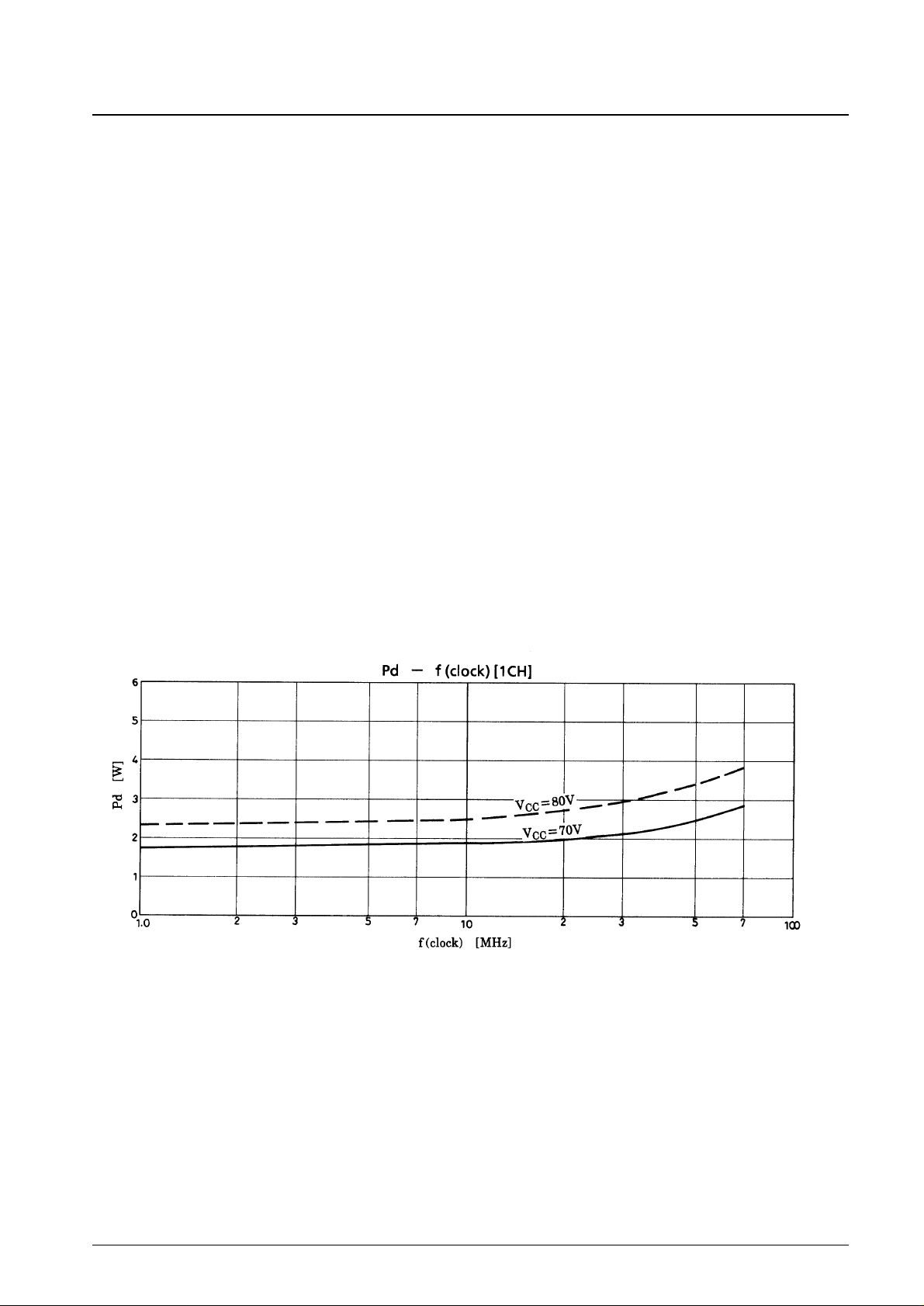
VP513 Thermal Design Example
Conditions: Using an fH= 64 kHz class monitor, fv = 70 MHz (clock)
VCC= 80 V, VBB= 10 V, V
OUT
= 50 Vp-p (CL= 10 pF)
Since this class of monitor can be operated up to Ta = 60°C, here we consider the case where the maximum clock
frequency is 70 MHz.
As mentioned previously, the chips with the largest loss are transistors Tr3 and Tr4. Determining those values gives:
Pc (Tr3) = 3.7 × 0.25 = 0.93 [W]............................................................ (5)
We determine ∆Tj by substituting the value for θj-c in equation (5).
∆Tj = 0.93 × 35 = 32.6 [°C].................................................................... (6)
Here, Tc(max) (measured at the back surface) will be under 100°C, and the value in item (6) above shows that it suffices
to focus on Tc(max) < 100°C in the thermal design to fulfill the Tj(max) < 150°C and Tc(max) < 100°C conditions.
Therefore, a heat sink that maintains the Tc < 100°C condition will have the following thermal resistance:
θh = ∆Tc ÷ Pd (TOTAL) = (Tc – Ta) ÷ [Pd (1CH) × 3]
= 40 ÷ (3.7 × 3) = 3.6°C/W
Thus the thermal resistance in this case is θh = 3.6 °C/W.
In actual practice, the ambient temperature and operating conditions will allow a heat sink smaller than that indicated by
this calculation to be used. Therefore, design optimization taking the actual conditions into account is also required.
Surge Protection
Surge protection is required when this device is connected to a CRT. This product requires the same protection as earlier
products.
1. Termination spark gap
2. Surge suppression resistor (Recommended value: 33 to 68 Ω)
3. Surge suppression diode (Installed in the vicinity of the IC output pin.)
Note: Caution: The value of surge suppression resistors must be determined taking both the stipulated discharge test and
the required frequency bandwidth into account.
No. 5331-6/8
VP513
Page 7
No. 5331-7/8
VP513
Application Notes
Mounting notes:
Since the specified heat sink is required to operate a mounted Video Pack, we recommend the following mounting
technique. (See the thermal design item for details on the required heat sink.) In particular, since the package used for this
product is even more compact than that used in the earlier VPS series, the following points require special care. (These
are recommendations.)
1. A tightening torque of between 0.39 and 0.88 N·m is recommended.
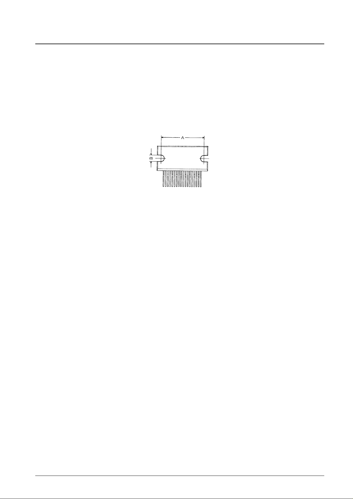
2. The bolt hole spacing in the heat sink should match that of the IC. In particular, the bolt hole spacing should be pulled
in to be as close as possible, within the range that mounting is possible, to the dimensions A and B in the package
dimensions drawing, as shown below.
3. Use either the truss screws (truss bolts) or binding screws stipulated in the JIS standards as the mounting bolts. Also,
use washers to protect the IC case.
4. Foreign matter, such as machining chips, must not be left trapped between the IC case and the heat sink. If grease is
applied to the junction surface, be sure to apply the grease evenly.
5. Solder the IC leads to the printed circuit board after mounting the heat sink to the IC.
Note: The heat sink is absolutely required to operate this Video Pack. Never, in any situation, apply power to a Video
Pack as an independent device. The Video Pack may be destroyed.
Page 8
No. 5331-8/8
VP513
This catalog provides information as of December, 1997. Specifications and information herein are subject to
change without notice.
■ No products described or contained herein are intended for use in surgical implants, life-support systems, aerospace
equipment, nuclear power control systems, vehicles, disaster/crime-prevention equipment and the like, the failure of
which may directly or indirectly cause injury, death or property loss.
■ Anyone purchasing any products described or contained herein for an above-mentioned use shall:
➀ Accept full responsibility and indemnify and defend SANYO ELECTRIC CO., LTD., its affiliates, subsidiaries and
distributors and all their officers and employees, jointly and severally, against any and all claims and litigation and all
damages, cost and expenses associated with such use:
➁ Not impose any responsibility for any fault or negligence which may be cited in any such claim or litigation on
SANYO ELECTRIC CO., LTD., its affiliates, subsidiaries and distributors or any of their officers and employees
jointly or severally.
■ Information (including circuit diagrams and circuit parameters) herein is for example only; it is not guaranteed for
volume production. SANYO believes information herein is accurate and reliable, but no guarantees are made or implied
regarding its use or any infringements of intellectual property rights or other rights of third parties.
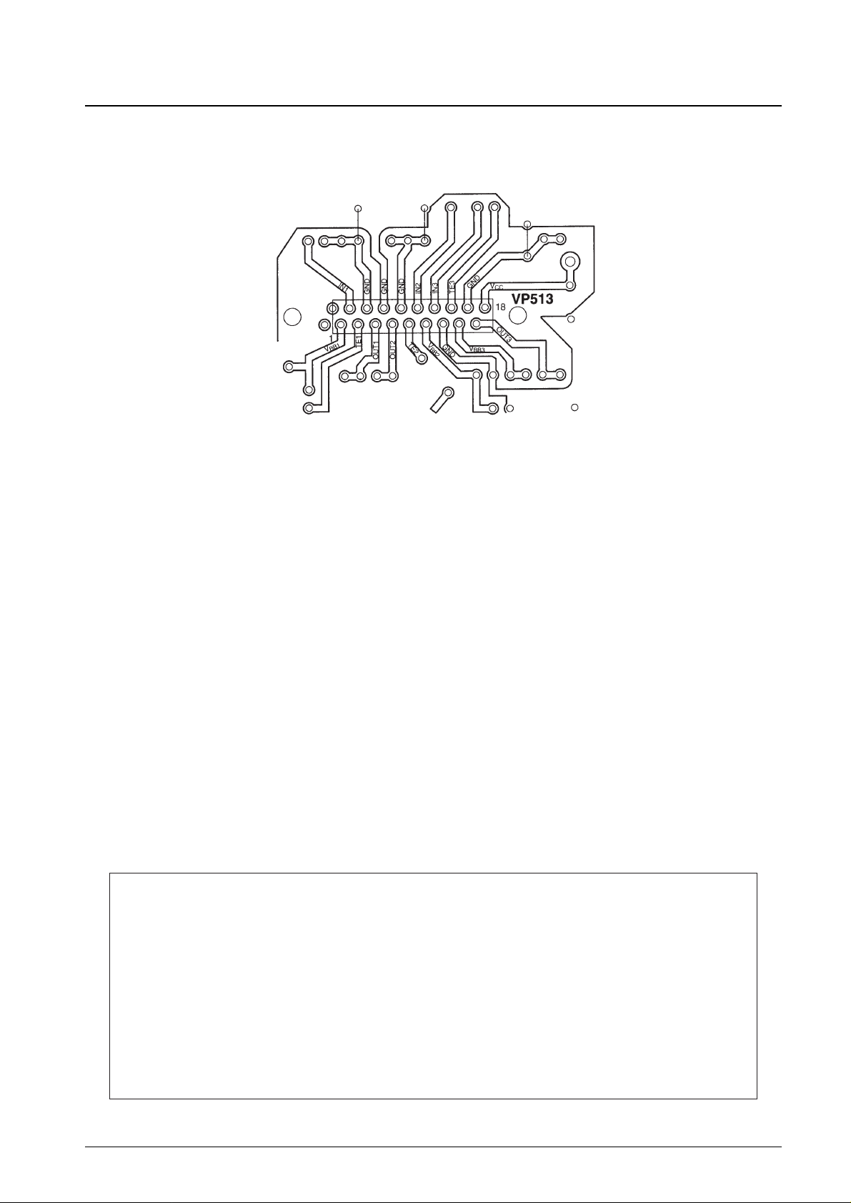
Peripheral wiring and ground leading:
The VP513 supports standard lead forming to a zigzag 2.54 mm pitch. Also, the pin layout is standardized to the I/O and
power supply line arrangement shown below.
IC Surrounding Pin Layout (Top view)
Note: Design applications that use two-sided printed circuit boards or similar technologies so that input and output lines
do not cross. Crossed lines can lead to increased crosstalk. Also, lines should be kept as short as possible, and the
ground plane should be made as wide as possible. These layout design principles will minimize bandwidth
degradation and oscillation.
 Loading...