


A6
103
•
•
•
•
•
•
•
•
•
查询TS53Y供应商
TS53Y
Vishay Sfernice
Surface Mount Miniature Trimmers
Single-Turn Cermet Sealed
FEATURES
0.20 Watt at 85°C
GAM T1
For PCB version see T53Y series
Excellent stability
Wide ohmic range
Low temperature coefficient
Low contact resistance variation
The TS53 trimming potentiometer has been designed for
surface mount applications and offers volumetric efficiency
(5 x 5 x 2.7 mm) with high performance and stability.
The TS53 design is suitable for both manual or automatic
operation, and can withstand waves, vapor phase and reflow
soldering techniques.
Small size for optimum packing density
Suitable for both manual or automatic operation
DIMENSIONS in millimeters
TS53YL
5
6.4
0.20
Ø 2.5 MAX
0.9 X 0.20
a
2.30
c
2.7
1 X 0.20
5
b
RECOMMENDED
SOLDERING AREAS
TS53YJ
2
1.3
2
1.3
1.3
TS53YL
2
1.3
c
b
5.5
a
2.3
ADHESIVE PAD (detail)
3.2
0.10
L VERSION J VERSION
0.10
0.65
1.1
Ø 2.5 adhesive pad
CIRCUIT DIAGRAM
TS53YJ
2
b
4
ac
2.3
2.7
1 X 0.20
5
5
0.20
5.5
b
Ø 2.5 MAX
0.9 X 0.20
a
2.30
c
a
cruciform screwdriver slot
ø 2.5, width 0.5
(1)
CW
b
(2)
deep: 0.55
max deep (center): 0.7
www.vishay.com For technical questions, contact: sf
18 Revision: 19-Jan-04
c
(3)
cruciform screwdriver slot
ø 2.5, width 0.5
deep: 0.55
max deep (center): 0.7
er@vishay.com Document Number: 51008
∆
∆
10 Ω
M
M Ω
M Ω
≤
∆
≤
≤
∆
TS53Y
ELECTRICAL SPECIFICATIONS
Resistive Element
Electrical Travel
Resistance Range
Standard Series
Tolerance Standard
Power Rating Linear
Logarithmic
Temperature Coefficient
Limiting Element Voltage (Linear Law)
Contact Resistance Variation
End Resistance (Typical)
Dielectric Strength (RMS)
Insulation Resistance
MECHANICAL SPECIFICATIONS
Mechanical Travel
Operating Torque (max. Ncm) 1.5
End Stop Torque (max. Ncm) 3.5
Unit Weight (max. g)
270° ± 10°
0.15
Surface Mount Miniature Trimmers
Single-Turn Cermet Sealed
Cermet
220° ± 15°
to 1M Ω
1 - 2 - 5
± 20%
0.25W at 70°C
not applicable
See Standard Resistance Element Data
200V
1% or 3 Ω
0.1% or 3 Ω
1000V
6
10
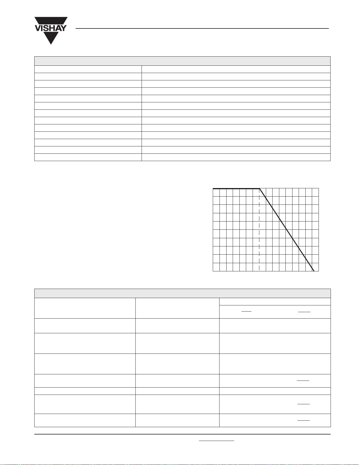
POWER RATING CHART
0.25
0.2
Vishay Sfernice
Ω
ENVIRONMENTAL SPECIFICATIONS
Temperature Range
Climatic Category
Sealing
– 55°C to + 125°C
55 / 125 / 56
sealed container
solder immersion IP67
PERFORMANCE
TESTS CONDITIONS
Load Life
Moisture Resistance
Long Term Damp Heat
Thermal Shock
Rotational Life (Electrical and Mechanical)
Shock
Vibration
90'/30' - ambient temperature + 85°C
10 cycles of 24 hours constituted
with damp heat - cold - vibrations
3 successive shocks in 3 directions
0.15
0.1
RATED POWER IN WATT
0.05
0
0
20
AMBIENT TEMPERATURE IN DEGREES CELSIUS
1000 hours at rated power
MIL STD 202 Method 106
Temperature 40°C - RH 93 %
56 days
55°C to + 125°C - 5 cycles ± 1 %
100 cycles - rated power ± 3 %
MIL STD 202 Method 213/1
100 g - 6 ms
MIL STD 202 Method 204/D
20 g - 12 hours
± 2% ± 3 %
Contact resistance variation: ∆ R < 1% Rn
± 2 % ± 3 %
Dielectric strength: 1000 V RMS
Insulation resistance: > 10
± 2 % ± 3 %
Dielectric strength: 1000 V RMS
Insulation resistance: > 10
± 1 %
± 1 %
40 60
TYPICAL VALUES AND DRIFTS
RT
RT
85 100 120 140
70
(%)
4
4
∆ V
155
R
1-2
(%)
R
1-2
1-2
± 2%
1-3
V
1-2
V
± 1%
1-3
V
1-2
V
± 1%
1-3
V
Document Number: 51008 For technical questions, contact: sf
Revision: 19-Jan-04 19
er@vishay.com www.vishay.com
TS53Y
Ω
YL
Vishay Sfernice
Surface Mount Miniature Trimmers
Single-Turn Cermet Sealed
STANDARD RESISTANCE ELEMENT DATA
STANDARD
RESISTANCE
VALUES
10
20
50
100
200
500
1k
2k
5k
10k
20k
50k
100k
200k
500k
1M
MAX.
POWER
AT 85°C
LINEAR LAW
MAX.
WORKING
VO LTAGE
W V mA ppm/°C
0.20 1.41
3.16
4.47
6.32
14.1
31.6
44.7
63.2
0.2
0.2
0.2
0.08
0.04
100
141
200
200
200
2
10
20
MAX. CUR.
THROUGH
ELEMENT
141
100
63
45
32
20
14
10
6.3
4.5
3.2
2
1.4
1
0.4
0.2
T.C .
–55°C
+125°C
+ 200
± 100
MARKING
VISHAY trademark, ohmic value, manufacturing date.
The ohmic value is indicated by a 3 figure code, the first two
are significant figures, the third one is the multiplier.
Example: 100 = 10 Ω
101 = 100 Ω
102 = 1000 Ω
0
503 = 50000 Ω
SOLDERING RECOMMENDATIONS
Vapor phase: 215°C/20 to 40 seconds.
Reflow: 230°C/20 seconds.
Do not exceed peak 260°C or with an IRON 40W: 3 seconds
at 350°C.
Soldering is possible by wave, reflow and vapor phase.
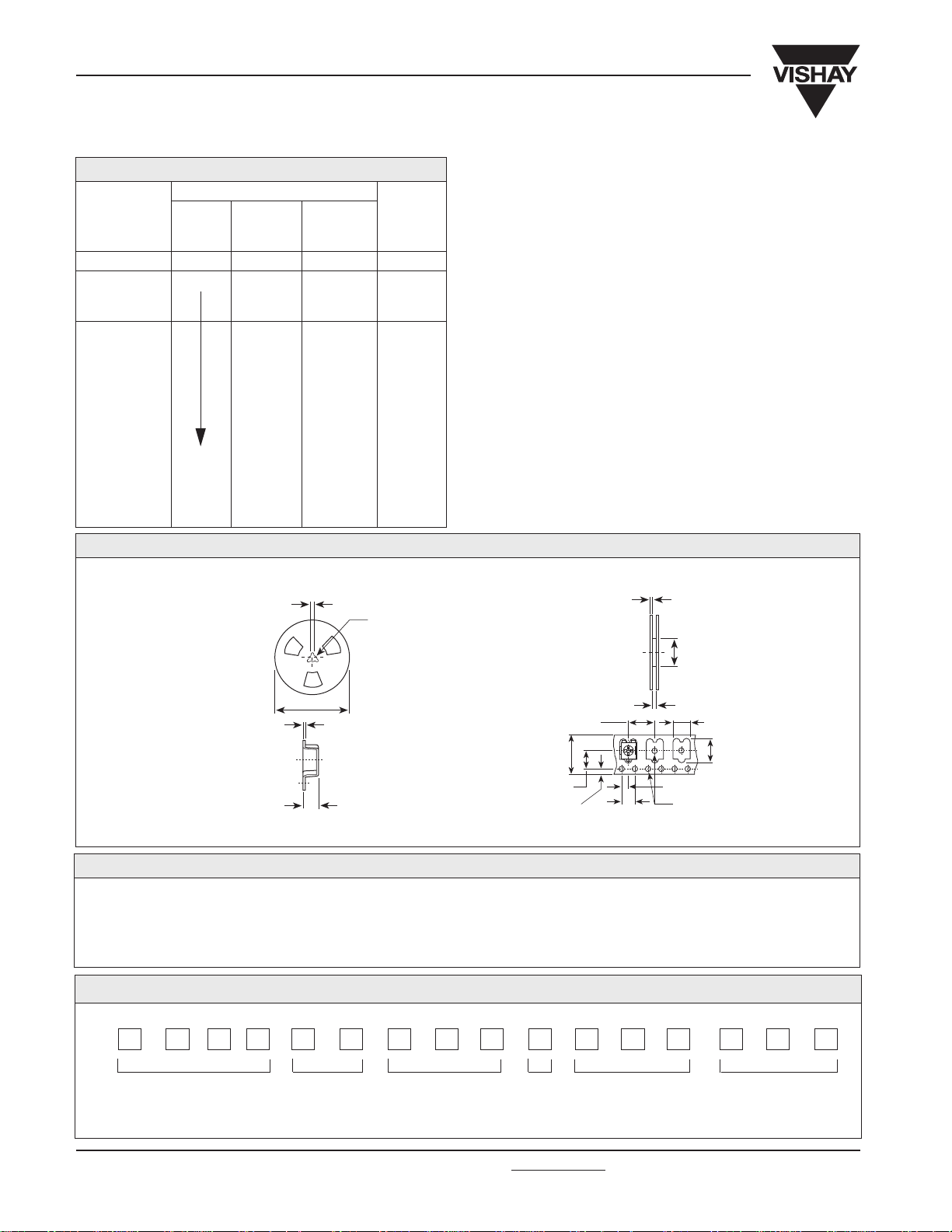
PACKAGING
On tape and reel of 500 pieces, code TR and 2000 pieces, code TR1
3 solts - width 2 to 120° - ø ext. 23
Ø 12.7
± 2
Ø 178
0.3
3.2
Cover tape panel strength specifications EIA 481 A and CEI 60286-3.
ORDERING INFORMATION
TS53
SERIES
STYLE
500K Ω
OHMIC VALUE
SAP PART NUMBERING GUIDELINES
12
5.5
1.75
± 20%
TOLERANCE
2
Ø 70
13
8
5.2
7.6
2
4
on request: TR1: Tape and reel 2000 pcs.
Ø 1.5
TR500
PACKAGING
TR: Tape and reel 500 pcs.
TS53YL 504MR10
MODEL
See the end of this data book for conversion tables
www.vishay.com For technical questions, contact: sf
20 Revision: 19-Jan-04
STYLE OHMIC
VALUE
TOL
er@vishay.com Document Number: 51008
PACKAGING
CODE
SPECIAL
(IF APPLICABLE)
 Loading...