


Quattro-SE
Pedestal
Operators Guide
V3851-4980
Robotic Camera Control Systems


Operators Guide
Quattro-SE
Pedestal
Publication Part No. V3851-4980
Issue 3 (December 2008)
Original Instructions
Copyright © Vitec Group plc 2008
All rights reserved throughout the world. No part of this document may be stored in a retrieval system. transmitted, copied or reproduced
in any way including, but not limited to, photocopy, photograph, magnetic or other record without the prior agreement and permission in
writing of Vitec Group plc.
Vinten Radamec® and Vinten® are registered trademarks of Vitec Group plc.


Preface
Thank you and congratulations on your new Quattro-SE
pedestal from Vinten Radamec
We want you to get the most from your new Quattro-SE pedestal, and therefore encourage you to read this
operators guide to familiarise yourself with its many features, some of which may be new to you. It also covers
essential health and safety information and a section on maintenance that will ensure you keep your new product in perfect condition.
To receive additional benefits, register with Vinten Radamec now by completing the enclosed form.
Features and benefits of your new Quattro-SE pedestal
The Quattro-SE is an encoded version of the Quattro-SL pedestal, it provides the floor and height position for
a virtual reality rendering system. The pedestal incorporates all the features and benefits of the Quattro-SL
which has been specifically designed to meet the exacting demands of camera operators working with full facility cameras.
• Position tracking
• Unique PDA user interface for ease of set-up
• Simple synchronising for VR studio software providers
• Suitable for a wide range of payloads up to 80 kg (176.4 lb).
• Narrow base and small footprint allow you to manoeuvre into smaller areas, tight sets and standard 30-inch doorways.
• Low-friction wheels reduce the steering effort, providing a sensitive feel.
• On-shot stroke of 100 cm (39.4 in.) and a maximum height of 149 cm (58.3 in.) provides in-creased
creative angles and means that raised platforms are not needed to obtain eyeline.
• The adjustable skirt is protected by the base, reducing damage and improving reliability and allowing close floor clearances for small-diameter cables.
Once again, thank you for choosing the Quattro-SE
We are confident it will give you many years of reliable performance
3

4

Safety - Read This First
Understanding these instructions
English
The original instructions presented in this operators guide were written in English, and subsequently
translated into other languages. If you are unable to understand these instructions, contact Vinten
Radamec or your distributor to obtain a translation of the original instructions (EU Countries).
БЪЛГАРСКИ
Оригиналните инструкции, представени в настоящото ръководство на производителя, бяха
написани на английски език, а след това - преведени на други езици. Ако не разбирате тези
езици, свържете се с Vinten Radamec или с Вашия дистрибутор, за да получите оригиналните
инструкции (за страните от Европейския съюз).
Česky
Pokyny uvedené v této operátorské příručce byly původně
přelo_eny do ostatních jazyků. Nerozumíte-li těmto pokynům, kontaktujte společnost Vinten Radamec
nebo svého distributora, abyste získali překlad originálních pokynů (členské státy EU).
Danish
De originale instruktioner, der præsenteres i denne betjeningsvejledning, er skrevet på engelsk og
derefter oversat til andre sprog. Hvis du ikke forstår disse instruktioner bedes du kontakte Vinten Radamec eller vor forhandler for at få en oversættelse af de originale instruktioner (EU-lande).
Deutsch
Die Originalanleitung in diesem Bedienungshandbuch wurde auf Englisch verfasst und anschließend
in andere Sprachen übersetzt. Bei Verständnisproblemen in einer der übersetzten Sprachen kontaktieren Sie bitte Vinten Radamec oder Ihren Fachhändler; dort erhalten Sie eine Übersetzung der ursprünglichen Anleitung (EU-Staaten).
Eesti
Käesoleva kasutajajuhendi algtekst on koostatud inglise keeles ning seejärel tõlgitud teistesse keeltesse. Kui juhend osutub teie jaoks arusaamatuks, võtke juhendi emakeelse tõlke hankimiseks ühendust Vinten Radameci või kohaliku esindajaga (Euroopa Liidu riigid).
Ελληνικά
Οι αρχικές οδηγίες αυτού του οδηγού για το χειριστή συντάχθηκαν στα Αγγλικά και μεταφράστηκαν στη
συνέχεια σε άλλες γλώσσες. Εάν δυσκολεύεστε να καταλάβετε αυτές τις οδηγίες, επικοινωνήστε με τη
Vinten Radamec ή το διανομέα
Español
Las instrucciones originales que se indican en esta guía del operador se han redactado en inglés y
posteriormente se han traducido a otros idiomas. Si no entiende estas instrucciones, póngase en contacto con Vinten Radamec o con su distribuidor para obtener una traducción de las instrucciones originales (para países de la UE).
Français
Les instructions originales présentées dans ce guide d'utilisation ont été écrites en anglais puis traduites dans d'autres langues. Si vous ne comprenez pas ces instructions, contactez Vinten Radamec
ou votre revendeur pour obtenir une traduction des instructions originales (pour les pays de l'UE).
Gaeilge
Scríobhadh na treoracha bunaidh don treoirleabhar oibritheora seo as Béarla, agus aistríodh iad go
teangacha eile ina dhiaidh sin. Mura bhfuil tú in ann na treoracha seo a thuiscint, téigh i dteagmháil le
Vinten Radamec nó le do dháileoir, chun aistriúchán de na treoracha bunaidh a fháil (Tíortha an AE).
Italiano
Le istruzioni originali presentate in questa guida per l'operatore sono in lingua inglese e successivamente tradotte nelle altre lingue. Qualora le istruzioni non fossero disponibili nella lingua desiderata,
potete contattare Vinten Radamec o il vostro distributore per ricevere la traduzione delle istruzioni originali (Paesi UE).
σας για να λάβετε μια μετάφραση των αρχικών οδηγιών (Χώρες ΕΕ).
napsány anglicky a následně byly
5

Latviešu
Šajā operatora rokasgrāmatā iekļautie norādījumi sākotnēji tika sarakstīti angļu valodā un pēc tam
pārtulkoti citās valodās. Ja nesaprotat šos norādījumus svešvalodā, sazinieties ar Vinten Radamec vai
tirgotāju, lai saņemtu norādījumu tulkojumu (kādā no ES dalībvalstu valodām).
Lietuvių
Šiame operatoriaus vadove pristatomos pirminės instrukcijos parašytos anglų kalba ir vėliau išverstos
į kitas kalbas. Jei šių instrukcijų nesuprantate, susisiekite su „Vinten Radamec“ arba savo platintoju ir
gaukite pirminių instrukcijų vertimą (ES šalies kalba).
Magyar
A kezeloi útmutatóban található utasítások angol nyelven íródtak, és utólag fordították azokat más
nyelvekre. Ha nem érti ezen utasításokat, kérjük, vegye fel a kapcsolatot a Vinten Radamecnel vagy
a helyi képviselettel, és igényelje az eredeti utasítások fordítását (EU országok).
Malti
L-istruzzjonijiet originali ippreżentati f'din il-gwida ta' operaturi kienu miktuba bl-Ingliż, u sussegwentement maqluba fl-lingwi ohra. Jekk ma tistax tifhem dawn l-istruzzjonijiet, ikkuntattja lil Vinten Radamec
jew id-distributur tieghek biex tikseb traduzzjoni ta' l-istruzzjonijiet originali (Pajjiżi ta' UE).
Nederlands
De oorspronkelijke instructies in deze bedieningshandleiding zijn geschreven in het Engels en vervolgens in andere talen vertaald. Als het onmogelijk is deze instructies te begrijpen, neemt u contact op
met Vinten Radamec of met uw distributeur om een vertaling te bemachtigen van de oorspronkelijke
instructies (EG-landen).
Polski
Oryginalne instrukcje zamieszczone w niniejszym podręczniku operatora zostały napisane w języku
angielskim, a następnie przetłumaczone na inne języki. Jeśli nie rozumieją Państwo tych instrukcji,
prosimy skontaktować się z siedzibą lub dystrybutorem Vinten Radamec, aby uzyskać tłumaczenie
oryginalnych instrukcji (kraje UE).
Português
As instruções originais apresentadas no guia do operador foram escritas em Inglês e traduzidas para
outros idiomas. Se não conseguir compreender estas instruções contacte a Vinten Radamec ou o seu
distribuidor para obter a tradução das instruções originais (Países da UE).
Română
Instrucţiunile originale prezentate în acest ghid pentru operatori au fost scrise în limba engleză, şi
traduse ulterior în alte limbi. În cazul în care nu înţelegeţi aceste instrucţiuni, contactaţi Vinten Radamec sau distribuitorul dumneavoastră pentru a obţine o traducere a instrucţiunilor originale (Ţările
UE).
Slovensky
Pôvodné pokyny, uvedené v tomto návode na obsluhu, boli napísané v anglictine a následne preložené do iných jazykov. Ak nerozumiete týmto pokynom, obrátte sa na spolocnost Vinten Radamec
alebo vášho distribútora, aby vám zaslal preklad originálnych pokynov (krajiny EÚ).
Slovenščina
Originalno besedilo teh navodil za uporabo je bilo napisano v angleščini in prevedeno v ostale jezike.
Če ne razumete teh navodil, se obrnite na podjetje Vinten Radamec ali lokalnega zastopnika, ki vam
bo posredoval originalna navodila (velja za dr_ave EU).
Suomi
Tähän käyttäjän oppaaseen sisältyvät ohjeet on kirjoitettu alun perin englanniksi ja käännetty sitten
muille kielille. Ellet ymmärrä näitä ohjeita, ota yhteyttä Vinten Radameciin tai jälleenmyyjään ja pyydä
alkuperäisten ohjeiden käännöstä (EU-maat).
Svenska
Instruktionerna i denna handbok skrevs ursprungligen på engelska och har sedan översatts till flera
språk. Om du inte förstår dessa instruktioner, kontakta Vinten Radamec eller din återförsäljare för en
ny översättning av originalinstruktionerna (EU-länder).
6

Warning symbols in this operators guide
80 kg
122
kg
13.1 bar
Where there is a risk of personal injury or injury to others, comments appear highlighted by the
word WARNING!—supported by the warning triangle symbol.
Where there is a risk of damage to the product, associated equipment, process or surroundings,
comments appear highlighted by the word CAUTION!
Warning symbols on the product
On encountering the warning triangle
and open book symbols it is imperative
that you consult this operators guide
before using this product or attempting
any adjustment or repair.
Where there is a risk of exposure to
laser radiation, comments appear supported by the laser warning triangle
symbol.
Critical data
Load
Maximum load . . . . . . . . . . . . . . . . . . . . . . . . . . . . . . . . . . . . . . . . . . . 80 kg (176.4 lb)
Mass
Pedestal . . . . . . . . . . . . . . . . . . . . . . . . . . . . . . . . . . . . . . . . . . . . . . . . . 144 kg (317 lb)
Trim weights (10 off) total . . . . . . . . . . . . . . . . . . . . . . . . . . . . . . . . . . . . 7.0 kg (15.4 lb)
Where there is a risk of electric shock,
comments appear supported by the
hazardous voltage warning triangle
symbol.
Pressure
Maximum pressure . . . . . . . . . . . . . . . . . . . . . . . . . . . . . . . . . . . . . . . 13.1 bar (190 psi)
Minimum pressure. . . . . . . . . . . . . . . . . . . . . . . . . . . . . . . . . . . . . . . . . . 3.5 bar (50 psi)
Volume
Internal volume . . . . . . . . . . . . . . . . . . . . . . . . . . . . . . . . . . . . . . . . . . . 6.13 L (1.62 gal)
Temperature
Operational temperature range . . . . . . . . . . . . . . . . . . . -40°C / +60°C (-40°F / +140°F)
Laser radiation
Laser class . . . . . . . . . . . . . . . . . . . . . . . . . . . . . . . . . . . . . . . . . . Class 2 laser product
7

Regulatory information
This product conforms to the following European Directives:
2004/108/EC (Electromagnetic Compatibility Directive)
97/23/EC (Pressure Equipment Directive)
This product has been tested to the following test standards:
EMC:
EN 61000-6-4:2001
EN 61000-6-2:2001
EN 61000-3-2:2000
EN 61000-3-3:1995 (+A1)
FCC:
CFR 47:2006 Class A
WEEE directive
WEEE Directive 2002/96/EC mandates the treatment, recovery and recycling of electric and
electronic equipment. This product is subject to WEEE disposal regulations. Please visit
www.vinten.com/recycle for details.
8

Contents
Page
Preface . . . . . . . . . . . . . . . . . . . . . . . . . . . . . . . . . . . . . . . . . . . . . . . . . . . . . . . . . . . . . . . . . . . . . . . . . . . . . . . 3
Safety - Read This First . . . . . . . . . . . . . . . . . . . . . . . . . . . . . . . . . . . . . . . . . . . . . . . . . . . . . . . . . . . . . . . . . 5
Critical data . . . . . . . . . . . . . . . . . . . . . . . . . . . . . . . . . . . . . . . . . . . . . . . . . . . . . . . . . . . . . . . . . . . . . . . . . . . 7
Regulatory information. . . . . . . . . . . . . . . . . . . . . . . . . . . . . . . . . . . . . . . . . . . . . . . . . . . . . . . . . . . . . . . . . . 8
Technical data . . . . . . . . . . . . . . . . . . . . . . . . . . . . . . . . . . . . . . . . . . . . . . . . . . . . . . . . . . . . . . . . . . . . . . . . 10
Usage . . . . . . . . . . . . . . . . . . . . . . . . . . . . . . . . . . . . . . . . . . . . . . . . . . . . . . . . . . . . . . . . . . . . . . . . . . . . . . . 11
Further information. . . . . . . . . . . . . . . . . . . . . . . . . . . . . . . . . . . . . . . . . . . . . . . . . . . . . . . . . . . . . . . . . . . . 11
Introduction . . . . . . . . . . . . . . . . . . . . . . . . . . . . . . . . . . . . . . . . . . . . . . . . . . . . . . . . . . . . . . . . . . . . . . . . . . 14
Operation
Unpacking . . . . . . . . . . . . . . . . . . . . . . . . . . . . . . . . . . . . . . . . . . . . . . . . . . . . . . . . . . . . . . . . . . . . . . . . . 15
Column check . . . . . . . . . . . . . . . . . . . . . . . . . . . . . . . . . . . . . . . . . . . . . . . . . . . . . . . . . . . . . . . . . . . . . . 15
Steering mechanism checks . . . . . . . . . . . . . . . . . . . . . . . . . . . . . . . . . . . . . . . . . . . . . . . . . . . . . . . . . . . 15
Fitting the load . . . . . . . . . . . . . . . . . . . . . . . . . . . . . . . . . . . . . . . . . . . . . . . . . . . . . . . . . . . . . . . . . . . . . . 16
Pressurizing the pedestal
Pressurizing the pedestal from an external pressure source . . . . . . . . . . . . . . . . . . . . . . . . . . . . . . . . 18
Pressurizing the pedestal using the Vinten portable pump. . . . . . . . . . . . . . . . . . . . . . . . . . . . . . . . . . 18
Balancing the load . . . . . . . . . . . . . . . . . . . . . . . . . . . . . . . . . . . . . . . . . . . . . . . . . . . . . . . . . . . . . . . . . . . 19
External connections . . . . . . . . . . . . . . . . . . . . . . . . . . . . . . . . . . . . . . . . . . . . . . . . . . . . . . . . . . . . . . . . . 20
Using the Quattro-SE pedestal
Height adjustment . . . . . . . . . . . . . . . . . . . . . . . . . . . . . . . . . . . . . . . . . . . . . . . . . . . . . . . . . . . . . . . . . 21
Steering . . . . . . . . . . . . . . . . . . . . . . . . . . . . . . . . . . . . . . . . . . . . . . . . . . . . . . . . . . . . . . . . . . . . . . . . 22
Cable clamps . . . . . . . . . . . . . . . . . . . . . . . . . . . . . . . . . . . . . . . . . . . . . . . . . . . . . . . . . . . . . . . . . . . . 22
Cable guard . . . . . . . . . . . . . . . . . . . . . . . . . . . . . . . . . . . . . . . . . . . . . . . . . . . . . . . . . . . . . . . . . . . . . 22
Transportation and storage . . . . . . . . . . . . . . . . . . . . . . . . . . . . . . . . . . . . . . . . . . . . . . . . . . . . . . . . . . . . 23
Servicing
General . . . . . . . . . . . . . . . . . . . . . . . . . . . . . . . . . . . . . . . . . . . . . . . . . . . . . . . . . . . . . . . . . . . . . . . . . . . 25
Routine maintenance. . . . . . . . . . . . . . . . . . . . . . . . . . . . . . . . . . . . . . . . . . . . . . . . . . . . . . . . . . . . . . . . .25
Cleaning. . . . . . . . . . . . . . . . . . . . . . . . . . . . . . . . . . . . . . . . . . . . . . . . . . . . . . . . . . . . . . . . . . . . . . . . . . . 25
Changing the steering ring. . . . . . . . . . . . . . . . . . . . . . . . . . . . . . . . . . . . . . . . . . . . . . . . . . . . . . . . . . . . . 27
Parts list . . . . . . . . . . . . . . . . . . . . . . . . . . . . . . . . . . . . . . . . . . . . . . . . . . . . . . . . . . . . . . . . . . . . . . . . . . . . . 28
Associated Publication
Quattro-SE Pedestal
Technical Manual
Part No. V3851-4990
9

Technical data
Payload . . . . . . . . . . . . . . . . . . . . . . . . . . . . . . . . . . . . . . . . . . . . . . . . . . . . . . . . . . . . . . . . . . . 80 kg (176.4 lb)
Pedestal weight. . . . . . . . . . . . . . . . . . . . . . . . . . . . . . . . . . . . . . . . . . . . . . . . . . . . . . . . . . . . . . 144 kg (317 lb)
Trim weights
main (5 x 1.0 kg) . . . . . . . . . . . . . . . . . . . . . . . . . . . . . . . . . . . . . . . . . . . . . . . . . . . . . . . . . . . 5.0 kg (11 lb)
auxiliary (6 x 0.5 kg). . . . . . . . . . . . . . . . . . . . . . . . . . . . . . . . . . . . . . . . . . . . . . . . . . . . . . . . . 3.0 kg (6.6 lb)
Minimum height . . . . . . . . . . . . . . . . . . . . . . . . . . . . . . . . . . . . . . . . . . . . . . . . . . . . . . . . . . . 48.9 cm (19.2 in.)
Maximum height . . . . . . . . . . . . . . . . . . . . . . . . . . . . . . . . . . . . . . . . . . . . . . . . . . . . . . . . . . 146.2 cm (57.6 in.)
On-shot stroke . . . . . . . . . . . . . . . . . . . . . . . . . . . . . . . . . . . . . . . . . . . . . . . . . . . . . . . . . . . . 97.3 cm (38.3 in.)
Doorway tracking width . . . . . . . . . . . . . . . . . . . . . . . . . . . . . . . . . . . . . . . . . . . . . . . . . . . . . . 82.5 cm (32.5 in.)
Transit doorway width . . . . . . . . . . . . . . . . . . . . . . . . . . . . . . . . . . . . . . . . . . . . . . . . . . . . . . . 81.6 cm (32.1 in.)
Maximum working pressure . . . . . . . . . . . . . . . . . . . . . . . . . . . . . . . . . . . . . . . . . . . . . . . . . . 13.1 bar (190 psi)
Relief valve pressure. . . . . . . . . . . . . . . . . . . . . . . . . . . . . . . . . . . . . . . . . . . . . . . . . . . . . . . . 14.5 bar (210 psi)
Minimum working pressure . . . . . . . . . . . . . . . . . . . . . . . . . . . . . . . . . . . . . . . . . . . . . . . . . . . . . 3.5 bar (50 psi)
Internal volume . . . . . . . . . . . . . . . . . . . . . . . . . . . . . . . . . . . . . . . . . . . . . . . . . . . . . . . . . . . . . 6.13 L (1.62 gal)
Operational temperature range . . . . . . . . . . . . . . . . . . . . . . . . . . . . . . . . . . . . . -40°C / +60°C (-40°F / +140°F)
Pedestal travel accuracy . . . . . . . . . . . . . . . . +/-5mm (+/-0.196 in.) over 3m (118.1 in.) straight line and return
Height travel accuracy. . . . . . . . . . . . . . . . . . . . . . . . . . . . . . . . . . . . . . . . . . . . . . . . . . . . +/-5mm (+/-0.196 in.)
Power consumption peak . . . . . . . . . . . . . . . . . . . . . . . . . . . . . . . . . . . . . . . . . . . . . . . . . . . . . . . . . . . . 13.2 W
Power input . . . . . . . . . . . . . . . . . . . . . . . . . . . . . . . . . . . . . . . . . . . . . . . . . . . . . . . . . . . . . . . . . . . . . . .12V DC
Shock insulation . . . . . . . . . . . . . . . . . . . . . . . . . . . . . . . . . . . . . . . . . . . . . . . . . . . . . Class I (basic insulation)
Laser class (opto sensors) . . . . . . . . . . . . . . . . . . . . . . . . . . . . . . . . . . . . . . . . . . . . . . . . Class 2 laser product
10

Usage
The Quattro-SE Pedestal is designed for use in virtual television studios to support and balance a pan and tilt
head, camera and ancillary equipment weighing up to 80 kg (176.4 lb).
The Quattro-SE Pedestal is intended for use by television camera operators.
WARNING! 1. Do NOT attempt to use this product if you do not understand how to
operate it.
2. Do NOT use this product for any other purpose than that specified in the
Usage statement above.
3. This product has been designed for indoor use. Protect from water, moisture and dust.
4. This product is intended for use on a flat, level studio floor surface.
5. Maintenance beyond that detailed in this Operators Guide must be performed only by competent personnel in accordance with the procedures
laid down in the Technical Manual.
6. This product has basic insulation only (class I) and for safety requires an
earth connection ('ground' in the U.S.A.).
Further information
For further information or advice regarding this pedestal, please contact Vinten Radamec or your local Vinten
Radamec distributor (see back cover) or visit our website. For full details on maintenance and spare parts,
please refer to the Quattro-SE Pedestal Technical Manual and Illustrated Parts List - Publication Part No.
V3851-4990.This is obtainable from Vinten Radamec or your local Vinten Radamec distributor. For information
on-line, visit our website at
www.vintenradamec.com
11

(1)
(2)
(3)
(26)(24)
(25)
(13)
(22)
(16)
(12) (11)
(4)
(14)
(15)
(23)
(6)
(21)
(5)
(7)
(8)
(9)
(17)
(19)
(20)
(10)
(11)
(7)
(18)
(10)
12
Fig 1 Quattro-SE Pedestal

Quattro-SE Pedestal (Fig 1)
(1) . . . . . . . . . . . . . . . . . . . . . . . . . . . . . . . . . . . . . . . . . . . . . . . . . . . . . . . . . . . . . . . . . . . . . . . . . . . Weight tray
(2) . . . . . . . . . . . . . . . . . . . . . . . . . . . . . . . . . . . . . . . . . . . . . . . . . . . . . . . . . . . . . . . . . . . . . . . . . . Safety catch
(3) . . . . . . . . . . . . . . . . . . . . . . . . . . . . . . . . . . . . . . . . . . . . . . . . . . . . . . . . . . . . . . . . . . . . . . . . . . Steering ring
(4) . . . . . . . . . . . . . . . . . . . . . . . . . . . . . . . . . . . . . . . . . . . . . . . . . . . . . . . . . . . . . . . . . . . . . . . . . . Drag control
(5) . . . . . . . . . . . . . . . . . . . . . . . . . . . . . . . . . . . . . . . . . . . . . . . . . . . . . . . . . . . . . . . . . Schrader valve and cap
(6) . . . . . . . . . . . . . . . . . . . . . . . . . . . . . . . . . . . . . . . . . . . . . . . . . . . . . . . . . . . . . . . . . . . . . . . Pressure gauge
(7) . . . . . . . . . . . . . . . . . . . . . . . . . . . . . . . . . . . . . . . . . . . . . . . . . . . . . . . . . . . . . . . . . . . . Trim weight stowage
(8) . . . . . . . . . . . . . . . . . . . . . . . . . . . . . . . . . . . . . . . . . . . . . . . . . . . . . . . . . . . . Cable guard adjustment knob
(9) . . . . . . . . . . . . . . . . . . . . . . . . . . . . . . . . . . . . . . . . . . . . . . . . . . . . . . . . . . . . . Cable guard height indicator
(10) . . . . . . . . . . . . . . . . . . . . . . . . . . . . . . . . . . . . . . . . . . . . . . . . . . . . . . . . . . . . . . . . . Opto sensor indicators
(11) . . . . . . . . . . . . . . . . . . . . . . . . . . . . . . . . . . . . . . . . . . . . . . . . . . . . . . . . . . . . . . . . . . . . . Position indicator
(12) . . . . . . . . . . . . . . . . . . . . . . . . . . . . . . . . . . . . . . . . . . . . . . . . . . . . . . . . . . . . . . . . . . . . . . . . .Cable Clamp
(13) . . . . . . . . . . . . . . . . . . . . . . . . . . . . . . . . . . . . . . . . . . . . . . . . . . . . . . . . . . . . . . . . . . . . . . . Lifting aperture
(14) . . . . . . . . . . . . . . . . . . . . . . . . . . . . . . . . . . . . . . . . . . . . . . . . . . . . . . . . . . . . Crab/steer changeover pedal
(15) . . . . . . . . . . . . . . . . . . . . . . . . . . . . . . . . . . . . . . . . . . . . . . . . . . . . . . . . . . . . . . . . . . . . . . . . . Bearing strip
(16) . . . . . . . . . . . . . . . . . . . . . . . . . . . . . . . . . . . . . . . . . . . . . . . . . . . . . . . . . . . . . . . . . . . . . . . Moving column
(17) . . . . . . . . . . . . . . . . . . . . . . . . . . . . . . . . . . . . . . . . . . . . . . . . . . . . . . . . . Markable height indication scale
(18) . . . . . . . . . . . . . . . . . . . . . . . . . . . . . . . . . . . . . . . . . . . . . . . . . . . . . . . . . . . . . Cable management system
(19) . . . . . . . . . . . . . . . . . . . . . . . . . . . . . . . . . . . . . . . . . . . . . . . . . . . . . . . . . . . . . . . . . . . . . Steering indicator
(20) . . . . . . . . . . . . . . . . . . . . . . . . . . . . . . . . . . . . . . . . . . . . . . . . . . . . . . . . . . . . . . . . . . . . . . . On-shot clamp
(21) . . . . . . . . . . . . . . . . . . . . . . . . . . . . . . . . . . . . . . . . . . . . . . . . . . . . . . . . . . . . . . . . . .Trim weight - auxiliary
(22) . . . . . . . . . . . . . . . . . . . . . . . . . . . . . . . . . . . . . . . . . . . . . . . . . . . . . . . . . . . . . . . . . . . . Trim weight - main
(23) . . . . . . . . . . . . . . . . . . . . . . . . . . . . . . . . . . . . . . . . . . . . . . . . . . . . . . . . . . . . . . . Four-bolt mounting plate
(24) . . . . . . . . . . . . . . . . . . . . . . . . . . . . . . . . . . . . . . . . . . . . . . . . . . . . . . . . . . . . . . . . . . . . . . . . Ethernet port
(25) . . . . . . . . . . . . . . . . . . . . . . . . . . . . . . . . . . . . . . . . . . . . . . . . . . . . . . . . . . . . . . . . . . . . . . . . Power socket
(26) . . . . . . . . . . . . . . . . . . . . . . . . . . . . . . . . . . . . . . . . . . . . . . . . . . . . . . . . . . . . . . . . . . . . . . . . . Genlock port
13

Introduction
The Quattro-SE pedestal comprises a central four-stage telescopic column mounted in a steerable base.
The moving column (16) is pressurized from an external pressure source. A markable height indicator scale
(17) is provided on the second section of the column allowing the operator to record camera heights for shots.
A weight tray (1) is attached to the top of the column and trim weights (21), (22) are provided for fine balance.
The weight tray also provides a standard four-bolt mounting (23) for a pan and tilt head and the pedestal is
steered by means of a steering ring (3) mounted on its underside. A Large diameter steering ring is provided
as standard and is fitted with indicators (19) to show the straight-ahead position.
The column is locked in the fully-depressed position by two safety catches (2) on the weight tray which engage
with spigots at the base of the column. Drag control (4) is provided at the base of the column and an on-shot
clamp (20) is provided as a secondary ring below the steering ring.
The base is carried on three sets of twin 125 mm (5 in.) wheels. A continuous height-adjustable cable guard
with infinite positions is provided, raised and lowered by a single control knob (8) with a height indicator (9)
below. Stowage for the trim weights is provided on the upper surface of both the pedestal base (7) and cable
management system (18). Two cable clamps (12) are fitted to the vertical sides of the pedestal base. A crab/
steer pedal (14) allows the operator to switch between conventional and crab steering. Position indicators (11)
on each side and one corner of the base allow the camera operator to accurately position the pedestal. Lifting
apertures (13) are provided on each face of the base and these also provide access to the wheels. Opto sensor
indicators (10) show the position of the sensors to aid targeting.
Connections for pedestal power (25), electronic positional feedback (24) and Genlock (26) are provided via the
cable management system (18).
14

Operation
Unpacking
Unpack the pedestal, ensuring that all transport packing and retaining fixings are removed.
WARNING! 1. Do NOT lift the pedestal by the steering ring, it may fail. Use the lifting
apertures (13).
2. Do NOT lift unassisted. The Quattro-SE pedestal has a mass of 144 kg
(317 lb). Take care when lifting the pedestal.
3. Do NOT release the safety catches (2) at this stage, the pedestal may
become unstable.
4. Do NOT leave the pedestal unattended on a sloping surface, to prevent it
rolling away.
Column check
WARNING! A pressure retaining valve prevents pedestal pressure being reduced
below approximately 3.5 bar (50 psi), indicated by the yellow segment on
the pressure gauge (6).
CAUTION! Do NOT attempt to extend the column if the pressure (6) has dropped below 3.5 bar (50
psi), or the pedestal may be damaged.
Ensure pedestal pressure is approximately 3.5 bar (50 psi). Increase or reduce as necessary, using the
Schrader valve (5).
Remove the self-adhesive safety catch warning covers (if fitted).
Push down on the weight tray (1) against residual pressure. At the safety catches (2), push the rocker switches
to the unlocked position. Allow the column to extend under hand restraint.
Exercise the column several times over its full stroke.
Push down on the weight tray (1) and push the safety catch rocker switches (2) to the locked position.
Steering mechanism checks
Steering indicators fitted to the steering ring comprises two groups of rivets on the underside of the steering
(19) as shown in (Fig 6) on page 27.
Align a steering indicator (19) with the crab/steer pedal (14). Press the pedal to select CRAB Turn the steering
ring and check that all three wheels turn together and all point in the same direction.
Align a steering indicator (19) with the crab/steer pedal (14) and press the pedal to select STEER. Turn the
steering ring and check that two of the wheels lock in the straight-ahead position and that the third wheel (below
the crab/steer pedal) can be turned by the steering ring.
15

Fitting the load
The Quattro pedestal has the standard four-bolt mounting plate (23) which permits the use of various Vinten
camera mounts including pan and tilt heads, Quickfix and Mitchell adapters. To fit a pan and tilt head or an
adaptor it is necessary to extend the moving column.
WARNING! 1. Do NOT lean over the pedestal when releasing the safety catches.
An over pressurized pedestal may rise rapidly when the safety catches are
released, causing personal injury.
2. Always restrain the column by hand pressure on the weight tray when
the safety catches are released.
Fit the pan and tilt head or adaptor as follows:
1. Ensure pedestal pressure does not exceed 3.5 bar (50 psi). Reduce as necessary, using the Schrader
valve cap (5).
WARNING! A pressure retaining valve prevents pedestal pressure being reduced
CAUTION! Do NOT attempt to extend the column if the pressure (6) has dropped below 3.5 bar (50
psi), or the pedestal may be damaged.
2. Push down on the weight tray (1) against residual pressure. At the safety catches (2), push the rocker
switches to the unlocked position. Allow the column to extend under hand restraint.
3. Apply the on-shot clamp (20).
4. Fit the pan and tilt head or adaptor and secure with the appropriate bolts.
WARNING! 1. Secure auxiliary equipment to the pedestal according to the manufac-
5. Release the on-shot clamp (20) and lower the moving column under hand restraint. Push down on the
weight tray (1) and push the safety catch rocker switches to the locked position.
below approximately 3.5 bar (50 psi), indicated by the yellow segment on
the pressure gauge (6).
turer’s instructions.
2. Only fit suitable equipment to the four-bolt fixing.
WARNING! Lock the pedestal in the fully depressed position before installing the cam-
era, to provide a stable mounting surface.
6. With the pedestal locked in the fully depressed position, fit the camera and accessories to the pan and
tilt head, ensuring that all items such as pan bars, prompters, lenses etc, are fitted. Attaching these
items at a later stage may upset the pedestal balance.
16
7. Install one main (22) and two auxiliary trim weights (21) on the weight tray (1).
0 10 20 30 40 50 60 70
90
200
160140120100806040200
lb
kg
0
2
4
6
8
10
12
14
bar
0
20
40
60
80
100
120
140
160
180
200
psi
13.1 bar
(190 psi)
80
180
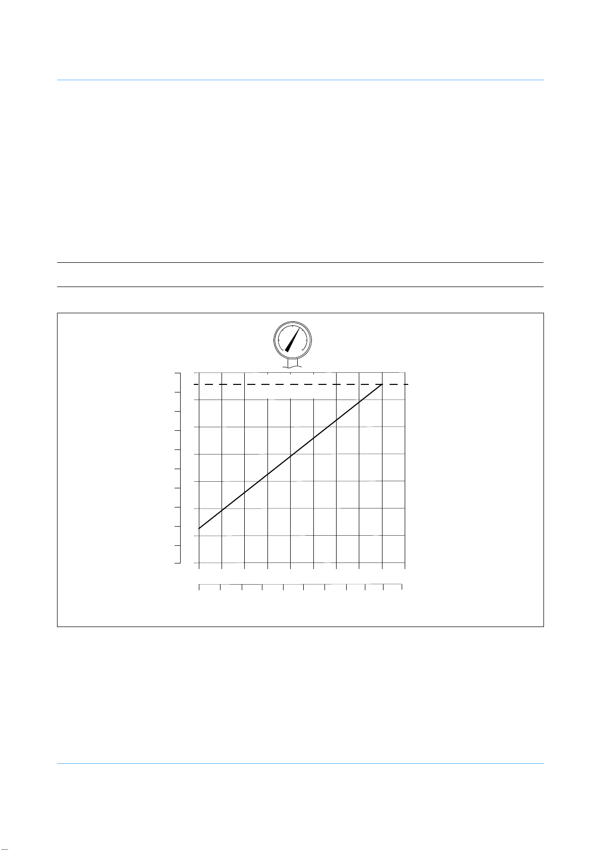
Pressurizing the pedestal
The Quattro may be pressurized from an external pressure source or by using the Vinten portable pump (Part
No. 3357-3). Trim weights (22, 23) are provided for fine balance.
Ascertain the payload to be fitted to the pedestal (payload = pan and tilt head, camera, lens and all ancillary
equipment). Referring to the graph (Fig 2) on page 17, mark the payload on the horizontal axis then strike a
vertical line from the load figure to the balance line. At the intersecting point strike a horizontal line to the vertical
axis and read off the required pressure.
The pedestal should be pressurized with the column collapsed but unlocked and free to extend.
Note: The pedestal internal pressure is greatest when the column is fully collapsed.
Fig 2 Balance Graph
17

Pressurizing the pedestal from an external pressure source
WARNING! 1. This pedestal must be pressurized only with clean, dry air or nitrogen, or
the pedestal may be damaged.
2. A pressure reducing valve must be fitted to the pressure line between the
gas cylinder and the outlet connection of the hose. The reducing valve
must be screwed into the gas cylinder outlet. The maximum pressure on
the outlet side of the reducing valve must not exceed 13.1 bar (190 psi).
3. Do not pressurize the pedestal beyond the maximum safe working pressure indicated by the leading edge of the red sector on the gauge, to prevent pedestal damage or personal injury.
4. The pedestal is fitted with a pressure relief valve as a safeguard against
over-pressurization. Do not attempt to adjust the pressure relief valve.
To pressurize the pedestal from an external pressure source, proceed as follows:
1. Remove the Schrader valve cap (5) and connect the charging line from the pressure source.
2. Push down on the weight tray (1) against residual pressure. At the safety catches (2), push the rocker
switches to the unlocked position and leave the column fully collapsed.
3. Turn on the pressure supply and slowly increase the pedestal pressure to the required pressure. Do
not exceed the maximum working pressure, indicated by the leading edge of the red sector on the
gauge (6).
4. Disconnect the charging line, but do not refit the Schrader valve cap at this stage.
Pressurizing the pedestal using the Vinten portable pump.
WARNING! 1. Do not pressurize the pedestal beyond the maximum safe working pres-
sure indicated by the leading edge of the red sector on the gauge, to prevent pedestal damage or personal injury.
2. The pedestal is fitted with a pressure relief valve as a safeguard against
over-pressurization. Do not attempt to adjust the pressure relief valve.
18

Fig 3 Vinten portable pump
(P.1)
(P.5)
(P.2)
(P.4)
(P.3)
To pressurize the pedestal using the Vinten portable pump, proceed as follows:
1. Remove the Schrader valve cap (5).
2. On the pump (Fig 3), fold down both the feet (P.3).
3. Push in the handle release button (P.5) and move the handle (P.1) to the horizontal position, where it
will lock.
4. Pull the hose (P.4) out of its stowage (P.2). Connect the hose to the pedestal charging valve (5).
5. On the pedestal, push down on the weight tray (1) against residual pressure. At the safety catches
(2), push the rocker switches to the unlocked position.
6. Position the pump between the legs, standing with both feet on the fold-down feet (P.3).
7. Grip the handle (P.1) with both hands and, using full steady strokes, pressurize the pedestal to the
required pressure. Do not exceed the maximum working pressure, indicated by the leading edge of the
red sector on the gauge (6). Approximately 600 strokes will be required to fully charge the pedestal.
8. Disconnect the hose (P.4) from the pedestal charging valve, but do not refit the Schrader valve cap at
this stage. Fit the hose in its stowage (P.2).
9. Push the pump plunger fully down, push in the handle release button (P.5) and move the handle (P.1)
to the vertical position, where it will lock the pump plunger in the closed position.
10. Fold up both the feet (P.3).
Balancing the load
After pressurization of the pedestal, the pan and tilt head and payload can be accurately balanced, as follows:
1. Exercise the moving column (16) over its full travel at least twice, then position the column in the midheight position.
19

CAUTION! A pressure retaining valve prevents pedestal pressure being reduced below approxi-
(26.1)
(25.1)
(24.1)
(6)
(10.1)
mately 3.5 bar (50 psi), to prevent damage to the pedestal.
2. If the column tends to fall, remove a trim weight (22, 23) or increase pressure.
3. If the column tends to rise, reduce the pressure in steps of 0.15-0.20 bar (2-3 psi) using the Schrader
valve cap (5).
CAUTION! The Schrader valve cap (5) forms a primary pressure seal. Always replace the cap and
screw it down finger-tight to prevent pressure loss.
Refit the Schrader valve cap (5).
A correctly pressurized pedestal will balance its payload such that it can be moved to any position over
the full on-shot stroke of the moving column, with minimum effort, and it will maintain its position when
the steering ring is released.
Fine balance and temperature correction may be achieved by adding or removing trim weights.
External connections
The Quattro-SE pedestal has a cable management system (18) which feeds the connecting cables from the
three external ports located on the top of the base next to the pressure gauge (6), to the camera, Head Processing Module and pan and tilt head mounted on the weight tray (1). This self-coiling system neatly stows the cable
as the moving column (16) rises and falls.
The cable management system (Fig 4) locates in the pedestal trim weight stowage slots nearest the pressure
gauge (6) and provides substitute trim weight stowage (10.1) in its base.
Fig 4 Pedestal external connections
20

Power Socket
The power cable plugs into the power socket (25.1), providing power to the pedestal from the Head Processing
Module via the power plug (25). For more information refer to the Head Processing Module Operators Guide
(Publication Part No. V3851-4981).
Ethernet port
The ethernet cable connects to the pedestal ethernet port (24.1), from the ethernet socket on the Head
Processing Unit via the ethernet connector (24). For more information refer to the Head Processing Module
Operators Guide (Publication Part No. V3851-4981).
Genlock port
The Genlock cable connects to the pedestal Genlock port (26.1), from the Genlock output socket on the Head
Processing Unit via the Genlock connector (26). For more information refer to the Head Processing Module
Operators Guide (Publication Part No. V3851-4981).
Using the Quattro-SE pedestal
Height adjustment
The column (16) has an on-shot stroke of 97.3 cm (38.3 in.) and the load can be moved over this distance, in
perfect balance, by raising and lowering the steering ring (3). The movement is adjustable for drag (4) and an
on-shot clamp (20) can be used to hold the moving column in position if fixed height operation is required. A
markable height indication scale (17) is provided on the second stage of the column. Operators can use this
scale to record working heights to be returned to whilst shooting.
WARNING! 1. Take care not to trap fingers under the steering hub, in cable manage-
ment components or between column elements while the pedestal height is
being reduced.
2. Reduce pedestal height to a minimum when moving between studios
over uneven or sloped surfaces, to ensure maximum stability.
3. Do NOT leave the pedestal unattended on a sloping surface, or it may roll
away.
CAUTION! Do NOT use the on-shot clamp (20) to raise and lower the moving column (16). Use the
the steering ring (3) to avoid damaging the pedestal.
Drag control
Column movement is adjustable for drag and this is set according to operator preference by means of the drag
control (4) located at the base of the moving column. Turn the control clockwise to increase the drag setting,
and counter- clockwise to decease it.
On-shot clamp
An on-shot clamp (20), located below the steering ring, is used to hold the column in position if fixed height
operation is required. Rotate the ring fully clockwise to apply the clamp. Rotate the ring fully counter-clockwise
to release the clamp.
21

CAUTION! 1. Do NOT force the moving column (16) either upward or downward when the column
lock is applied, to avoid damaging the pedestal.
2. Do NOT use the on-shot clamp (20) to raise and lower the moving column (16). Use
the steering ring (3) to avoid damaging the pedestal.
Steering
Directional control of the pedestal is achieved by turning the steering ring (3) mounted at the top of the column.
The steering system is geared so that the wheels turn by the same amount as the steering ring. This ensures,
for example, that with the pedestal set to crab, turning the steering ring by 90° will also cause the pedestal to
change direction by 90°. The steering ring is fitted with indicators (19) which indicate the straight-ahead position, providing a reference point when steering.
Note: The Quattro-SE may be supplied with a steering ring with either a moulded steering
Position indicators (11) in the centre of each vertical face of the base and on one corner, allow the camera operator to accurately position the pedestal.
The pedestal has a crab/steer arrangement with a foot-operated changeover mechanism, which provides a
steer setting - one wheel steering, two fixed; or a crab setting - all three wheels turning together. Pushing the
pedal (14) operates the changeover mechanism which toggles the pedestal between crab and steer.
Although the button can be pressed with the wheels in any position, the changeover will not occur until the
wheels are all facing forward, so the steering ring may have to be turned by up to 180° before the changeover
mechanism engages. This arrangement ensures that the fixed wheels will always lock in the straight-ahead
position when changing from crab to steer.
Steering rings of two diameters and with either type of steering indicator may be fitted (See Changing the
steering ring on page 27).
Note: Turning the pedestal too sharply at high speed will cause the wheels to slip and adversely
indicator on the topside, or rivets (19) (illustrated) on the underside of the steering ring.
affects pedestal positional feedback accuracy.
Pedestal navigation requires that all three wheels are parallel and that the one steering
wheel is not misaligned by 180°—in the event of such steering misalignment the PDA
software will prompt the operator to rotate the steering wheel by 180°.
Cable clamps
Two cable clamps (12) are provided, mounted on the vertical faces of the base.
Cable guard
An infinitely adjustable, continuous cable guard is provided in the skirt of the base, raised and lowered by
means of a single knob (8). Height of the cable guard is displayed by a cable guard height indicator (9) positioned below the adjustment knob.
Rotate the adjustment knob to set the cable guard to the required height.
The cable guard incorporates a spring-loaded mechanism to prevent damage if the pedestal is pulled over an
obstacle.
22

Transportation and storage
WARNING! 1. Do NOT lift the pedestal by the steering ring, it may fail. Use the lifting
Note: It is not necessary to reduce the pedestal pressure prior to transportation or storage.
To prepare the pedestal for transportation and storage, proceed as follows:
Fully depress the moving column (16). Push down on the weight tray (1) and push the safety catch rocker
switches (2) to the locked position
WARNING! A pressure retaining valve prevents pedestal pressure being reduced
apertures (13).
2. Do NOT lift unassisted. The Quattro-SE pedestal has a mass of 144 kg
(317 lb). Take care when lifting the pedestal.
2. Local, national or international regulations may apply to the transport
and storage of pressurized pedestals.
3. Do NOT leave the pedestal unattended on a sloping surface, to prevent it
rolling away.
below approximately 3.5 bar (50 psi), to prevent damage to the pedestal.
Using the Schrader valve cap (5), reduce pedestal pressure to 3.5 bar (50 psi).
Remove camera, prompter and any other ancillaries.
WARNING! 1. Do NOT lean over the pedestal when releasing the safety catches.
Push down on the weight tray (2). At the safety catches (3), push the rocker switches to the unlocked
position. Allow the column to extend under hand restraint.
Apply the on-shot clamp (6).
Undo the four mounting bolts (23) and remove the pan and tilt head.
Place any trim weights (21), (22) in the trim weight stowage (7).
An over pressurized pedestal may rise rapidly when the safety catches are
released, causing personal injury.
2. Always restrain the column by hand pressure on the weight tray when
the safety catches are released.
23

To avoid the possibility of dust or abrasive particles collecting on moving components, release the onshot clamp (20) and set the moving column (16) to minimum height. Push down on the weight tray (1)
and push the safety catch rocker switches (2) to the locked position.
WARNING! This pedestal must be transported and stored in an upright position with
the column collapsed and the safety catches (2) locked, to ensure stability.
24

Servicing
(27)
(27)
General
The Quattro-SE pedestal is robustly made to high engineering standards and little attention is required to maintain serviceability save regular cleaning. Attention to the following points will ensure a long and useful service
life with minimum need for repair.
Routine maintenance
The Quattro-SE pedestal requires no routine maintenance other than regular cleaning.
During normal use, check the steering alignment, the effectiveness of the on-shot clamp and safety catches
and check for radial or side play in the moving column. The navigation data should also be checked, ensuring
that the pedestal remains calibrated to the floor target.
Once a year, check the relief valve activates between 14.48–14.82 bar (210–215 psi) by collapsing the column,
engaging the safety catches and observing the pressure gauge while pressurising the pedestal until the relief
valve activates.
Refer to the appropriate section in the Technical Manual if the steering is misaligned, the on-shot clamp is ineffective, excessive radial or side play is apparent in the moving column, the pressure relief valve setting is
incorrect or any other defect is apparent.
Adjustments and repairs should be carried out only by a competent person.
Cleaning
During normal studio use, the only cleaning required should be a regular wipe over with a lint-free cloth. Dirt
accumulated during storage or periods of disuse may be removed with a semi-stiff brush. Particular attention
should be paid to the opto sensors (Fig 5) column bearing strips (15) and to the wheels, which are accessible
for cleaning through the lifting apertures (13).
Fig 5 Opto sensors location
25

WARNING! Do NOT operate the steering while reaching inside the base to clean
wheels, you may be injured.
CAUTION! 1. Do NOT use oil or grease on any exposed part of the column. This is unnecessary
and traps dirt which acts as an abrasive.
2. Use only detergent-based cleaners. Do NOT use solvent- or oil-based cleaners, abrasives or wire brushes to remove accumulations of dirt, as these damage the protective
surfaces.
The two opto sensors (27) are located on the underside of the pedestal base (Fig 5), next to the two wheels
beneath the trim weight stowage slots (7). To clean the opto sensors (27) there is no need to upturn the pedestal base, simply proceed as follows:
1. Disconnect power from the base (25).
2. Fully depress the column, engage the safety catches and remove the camera and accessories from
the pan and tilt head.
3. Ensure pedestal pressure does not exceed 3.5 bar (50 psi). Reduce as necessary, using the Schrader
valve cap (5).
4. Push down on the weight tray (1) against residual pressure and unlock the safety catches (2). Allow
the column to extend under hand restraint.
5. Apply the on-shot clamp (20).
6. Remove the pan and tilt head from the weight tray (1).
7. Release the on-shot clamp (20), fully depress the column and engage the safety catches (2).
WARNING! 1. Do NOT stare into beam from the opto sensors. Laser radiation, Class 2
8. With assistance, carefully turn the pedestal over onto the weight tray (1) by lifting at one corner of the
base using the lifting apertures (13).
CAUTION! Take care not to trap the ethernet, power and genlock cables where they pass through
the weight tray, when turning the pedestal onto the weight tray.
9. Clean the two opto sensors (27) using a lint-free cloth.
10. With assistance, carefully set the pedestal back onto its wheels by lifting at one corner of the base
using the lifting apertures (13).
laser product.
2. Disconnect power from the base (25) before working on the underside of
the pedestal.
26

Changing the steering ring
(3)
(19)
(3.1)
The Quattro-SE may be supplied with a steering ring with either a moulded steering indicator on the top or rivets
on the underside of the steering ring.
Note: If a steering ring with a moulded steering indicator is changed for one with rivets, or vice
To change the steering ring:
versa, it will be necessary to realign the steering mechanism. This should be carried out
by competent personnel in accordance with the procedures laid down in the Technical
Manual.
1. Fully extend the column and apply the on-shot clamp (20).
2. On the underside of the steering hub (Fig 6), remove four nyloc nuts (3.1) to release the steering ring
(3). Note the position of the steering indicators (19) and remove the steering ring.
3. Position the replacement steering ring on the steering hub with the steering indicator in the position
noted above.
4. Secure the steering ring with four nyloc nuts (3.1).
Fig 6 Steering hub
27

Parts list
The following lists include main assemblies, user-replaceable spare parts and optional accessories. For further
information regarding repair or spare parts, please contact Vinten Radamec or your local Vinten Radamec distributor.
For information on-line, visit our website at
www.vintenradamec.com
Item Part No.
Quattro-SE pedestal, with large steering ring and moulded steering indicators. . . . . . . . . . . . . . . V3851-0001
Quattro-SE pedestal, with large steering ring and rivet steering indicators . . . . . . . . . . . . . . . . . . V3851-0002
Trim weights
main . . . . . . . . . . . . . . . . . . . . . . . . . . . . . . . . . . . . . . . . . . . . . . . . . . . . . . . . . . . . . . . . . . . . . . . . . 3445-47
auxiliary . . . . . . . . . . . . . . . . . . . . . . . . . . . . . . . . . . . . . . . . . . . . . . . . . . . . . . . . . . . . . . . . . . . . . . 3445-48
Cable management loom . . . . . . . . . . . . . . . . . . . . . . . . . . . . . . . . . . . . . . . . . . . . . . . . . . . . . . . . V3851-1036
Optional accessories
Steering ring with rivet steering indicators . . . . . . . . . . . . . . . . . . . . . . . . . . . . . . . . . . . . . . . . . . . . . . 3445-49
Steering ring with moulded steering indicators . . . . . . . . . . . . . . . . . . . . . . . . . . . . . . . . . . . . . . . . . . . 3445-43
Spanner - for head bolts . . . . . . . . . . . . . . . . . . . . . . . . . . . . . . . . . . . . . . . . . . . . . . . . . . . . . . . . . . . J551-001
Vinten portable pump . . . . . . . . . . . . . . . . . . . . . . . . . . . . . . . . . . . . . . . . . . . . . . . . . . . . . . . . . . . . . . . 3357-3
PDA cable . . . . . . . . . . . . . . . . . . . . . . . . . . . . . . . . . . . . . . . . . . . . . . . . . . . . . . . . . . . . . . . . . . . . V3990-5077
Head encoders cable . . . . . . . . . . . . . . . . . . . . . . . . . . . . . . . . . . . . . . . . . . . . . . . . . . . . . . . . . . . V3980-5006
Head Processing Module (Vector 950E mounting bracket). . . . . . . . . . . . . . . . . . . . . . . . . . . . . . . V3851-1009
Head Processing Module (Vision 250E mounting bracket). . . . . . . . . . . . . . . . . . . . . . . . . . . . . . . V3851-1032
Vinten Radamec PDA . . . . . . . . . . . . . . . . . . . . . . . . . . . . . . . . . . . . . . . . . . . . . . . . . . . . . . . . . . . V4015-0001
Vector 950E pan and tilt head . . . . . . . . . . . . . . . . . . . . . . . . . . . . . . . . . . . . . . . . . . . . . . . . . . . . . V4004-0001
Vision 250E pan and tilt head . . . . . . . . . . . . . . . . . . . . . . . . . . . . . . . . . . . . . . . . . . . . . . . . . . . . . . . . . 3793-3
28
 Loading...