


Fusion FHR-35 Robotic Pan and Tilt Head
Fusion FHR-35
Robotic Pan and Tilt Head
Installation and Configuration Guide
Part No. V4096-0001
www.vintenradamec.com
Original Instructions: English
Copyright © 2013
All rights reserved throughout the world. No part of this document may be stored in a retrieval system, transmitted, copied or reproduced in any way, including, but not limited to, photocopy, photograph, magnetic or other record without the prior agreement and permission in writing of the Vitec Group plc.
Disclaimer
The information contained in this manual is believed to be correct at the time of printing. Vitec Videocom Ltd. reserves the right to make changes to the information or specifications without obligation to notify any person of such revision or changes. Changes will be incorporated in new versions of the publication.
We are making every effort to ensure that our manuals are updated on a regular basis to reflect changes to product specifications and features. Should this manual not contain information on the core functionality of your product, please let us know. You may be able to access the latest revision of this manual from our website.
Vitec Videocom Ltd. reserves the right to make changes to product design and functionality without notification.
Trademarks
All product trademarks and registered trademarks are the property of the Vitec Group plc.
All other trademarks and registered trademarks are the property of their respective companies.
Published by:
Vitec Videocom
Supports Technical Publications Dept.
William Vinten Building
Western Way
Bury St Edmunds
Suffolk IP33 3TB
E-mail: technical.publications@vitecgroup.com

FHR-35 Robotic Pan and Tilt Head
Contents
Safety and Warnings . . . . . . . . . . . . . . . . . . . . . . . . . . . . . . . . . . . . . . . . . . . . . . . . . . . . . . . . . . . . . . 2
Components and Connections . . . . . . . . . . . . . . . . . . . . . . . . . . . . . . . . . . . . . . . . . . . . . . . . . . . . . . 4
Installation . . . . . . . . . . . . . . . . . . . . . . . . . . . . . . . . . . . . . . . . . . . . . . . . . . . . . . . . . . . . . . . . . . . . . . 5
Box Contents and Tools Required . . . . . . . . . . . . . . . . . . . . . . . . . . . . . . . . . . . . . . . . . . . . . . . . . . 5
Mounting Supports and Adaptors . . . . . . . . . . . . . . . . . . . . . . . . . . . . . . . . . . . . . . . . . . . . . . . . . . 6
Cable Management Brackets . . . . . . . . . . . . . . . . . . . . . . . . . . . . . . . . . . . . . . . . . . . . . . . . . . . . . 7
Removing the Camera Cradle . . . . . . . . . . . . . . . . . . . . . . . . . . . . . . . . . . . . . . . . . . . . . . . . . . . . . 7
Setting the Pan and Tilt Mechanical Hard Stops . . . . . . . . . . . . . . . . . . . . . . . . . . . . . . . . . . . . . . . 8
Setting the Tilt Mechanical Hard Stops . . . . . . . . . . . . . . . . . . . . . . . . . . . . . . . . . . . . . . . . . . . . . . 9
Setting the Pan Mechanical Hard Stops . . . . . . . . . . . . . . . . . . . . . . . . . . . . . . . . . . . . . . . . . . . . 10
Ceiling Mounting . . . . . . . . . . . . . . . . . . . . . . . . . . . . . . . . . . . . . . . . . . . . . . . . . . . . . . . . . . . . . . . 11
Wall Mounting . . . . . . . . . . . . . . . . . . . . . . . . . . . . . . . . . . . . . . . . . . . . . . . . . . . . . . . . . . . . . . . . . 12
Pozi Loc Tripod Mounting Options . . . . . . . . . . . . . . . . . . . . . . . . . . . . . . . . . . . . . . . . . . . . . . . . . 13
HD Tripod Mounting Options . . . . . . . . . . . . . . . . . . . . . . . . . . . . . . . . . . . . . . . . . . . . . . . . . . . . . 15
Locking/Unlocking the Camera Cradle . . . . . . . . . . . . . . . . . . . . . . . . . . . . . . . . . . . . . . . . . . . . . 17
Mounting the Camera . . . . . . . . . . . . . . . . . . . . . . . . . . . . . . . . . . . . . . . . . . . . . . . . . . . . . . . . . . 17
Balancing the Head . . . . . . . . . . . . . . . . . . . . . . . . . . . . . . . . . . . . . . . . . . . . . . . . . . . . . . . . . . . . 18
Electrical Connections . . . . . . . . . . . . . . . . . . . . . . . . . . . . . . . . . . . . . . . . . . . . . . . . . . . . . . . . . . 20
Cable Management . . . . . . . . . . . . . . . . . . . . . . . . . . . . . . . . . . . . . . . . . . . . . . . . . . . . . . . . . . . . 21
Powering Up . . . . . . . . . . . . . . . . . . . . . . . . . . . . . . . . . . . . . . . . . . . . . . . . . . . . . . . . . . . . . . . . . 21
ICE Tool . . . . . . . . . . . . . . . . . . . . . . . . . . . . . . . . . . . . . . . . . . . . . . . . . . . . . . . . . . . . . . . . . . . . . . . . 22
ICE Tool Installation . . . . . . . . . . . . . . . . . . . . . . . . . . . . . . . . . . . . . . . . . . . . . . . . . . . . . . . . . . . . 22
Using ICE Tool . . . . . . . . . . . . . . . . . . . . . . . . . . . . . . . . . . . . . . . . . . . . . . . . . . . . . . . . . . . . . . . . 22
Setting the Zero Position and Soft Limits . . . . . . . . . . . . . . . . . . . . . . . . . . . . . . . . . . . . . . . . . . . 23
Soft Limits . . . . . . . . . . . . . . . . . . . . . . . . . . . . . . . . . . . . . . . . . . . . . . . . . . . . . . . . . . . . . . . . . . . 24
Configuration Settings . . . . . . . . . . . . . . . . . . . . . . . . . . . . . . . . . . . . . . . . . . . . . . . . . . . . . . . . . . 25
Maintenance . . . . . . . . . . . . . . . . . . . . . . . . . . . . . . . . . . . . . . . . . . . . . . . . . . . . . . . . . . . . . . . . . . . . 26
Troubleshooting . . . . . . . . . . . . . . . . . . . . . . . . . . . . . . . . . . . . . . . . . . . . . . . . . . . . . . . . . . . . . . . . . 27
General Notices. . . . . . . . . . . . . . . . . . . . . . . . . . . . . . . . . . . . . . . . . . . . . . . . . . . . . . . . . . . . . . . . . . 28
Installation and Configuration Guide
1

Installation and Configuration Guide
FHR-35 Robotic Pan and Tilt Head
Safety and Warnings
For your personal safety, read these instructions. Do not operate the product if you do not understand how to use it safely. Save these instructions for future reference.
Follow all warnings and instructions marked on the product and in this manual. Safety warnings are included in this manual. These safety instructions must be followed to avoid possible personal injury and damage to the product.
WARNING! Do not install this product onto a bracket, support or other equipment that is not designed to support the weight of the product and its payload. All supports must comply with local government regulations.
WARNING! The fitting of non-approved parts and accessories, or the carrying out of non-approved alterations or servicing can be dangerous and could affect the safety of the product. It may also invalidate the terms and conditions of the product warranty.
WARNING! Risk of personal injury. All personnel must be fully trained and adhere to correct manual handling techniques. It is the responsibility of the individual and the local organisation to enforce safe working practices at all times.
WARNING! Risk of personal injury or injury to others. All personnel must be fully trained and adhere to local health and safety laws and guidelines. It is the responsibility of the local organisation to enforce safe working practices at all times.
CAUTION! This product is designed for robotic use only and is operated remotely. Do not attempt to manually operate this product.
Electrical Connection
WARNING! This product must be connected to a power supply of the same voltage (V) and current (A) as indicated on the product and described in the specification section of this manual. To reduce the risk of electric shock, do not remove the covers. No user-servicable parts inside. Refer all servicing to qualified service personnel.
WARNING! The IEC connector is the primary disconnect device and must be accessible both during and after installation of the product.
WARNING! Inspect the AC cable regularly for signs of wear or damage. If the AC cable is damaged, the product must be returned to Vinten Radamec for repair.
Basic Electrical Insulation (Class 1 equipment)
WARNING! This product is Class 1 equipment. For safe operation this equipment must be connected to a power supply that has a protective earth connection (US: ground).
Ventilation and Overheating
CAUTION! Slots and openings are intended for ventilation purposes to ensure reliable operation of the product and protect it from overheating. Do not block or cover any slots and openings.
Cleaning and Maintenance
CAUTION! Do not use solvent or oil-based cleaners, abrasives or wire brushes to remove accumulations of dirt as these damage the protective surfaces. To clean mechanical surfaces, use only detergent-based cleaners.
2

FHR-35 Robotic Pan and Tilt Head
Safety and Warnings
CAUTION! Do not use oil or grease on any exposed part of the product. This is unnecessary and traps dirt which acts as an abrasive.
CAUTION! Risk of damage to equipment. Do not lift or carry the head by the top cover.
Intended Use
This product is designed for use within television studios to support and balance a camera together with ancillary equipment weighing up to 16 kg (35 lb). Camera operators can remotely control camera zoom and focus and movements about the pan and tilt axes using Vinten Radamec control systems.
Safe Working Environment
In normal operation, remote controlled equipment can
move suddenly and without warning. Since audible warnings are not suitable for use within the studio environment, it is recommended that only trained personnel be allowed to work in the active areas where remote controlled heads and pedestals are located.
Personnel should be made aware of the potential hazards of working in a robotic environment. To avoid personal injury, personnel should always exercise caution when working in the vicinity of robotic equipment. The forces are sufficient to cause personal injury or injury to others and therefore caution is essential.
Safe Operating Zone
The safe operating zone for personnel is a minimum of 1 m
(3 ft) outside of the footprint of the pan and tilt head. In most
installations, the teleprompter (if installed) is mounted on to the head and protrudes the furthest beyond the base of the head.
The footprint must take into account the overhang of the teleprompter and/or other payload equipment as the head moves about the pan axis.
Personnel need to be trained and aware of how far the head and pedestal can move, the speeds involved and the need to stay clear of robotic equipment at all times.
Warning Signs
Warning signs should be displayed prominently in the workplace alerting personnel that robotic equipment is in use and may move suddenly without warning.
If personnel are working on robotic or associated equipment, ensure a warning sign is placed at the controller (control panel) to alert operators that work is being carried out.
Safety Notes for Operators
Each remote controlled head and/or pedestal in the system
should remain within the view of the operator at all times. Do not operate a head and/or pedestal if it cannot be seen.
Before and during remote operation, the operator must verify visually that the active area is clear of hazards and personnel. If personnel are too close to a head or pedestal that is about to move, the operator should prevent the motion from starting or stop the motion after it has started.
Operators must familiarise themselves with the working footprint of the robotic head, including all associated equipment
(lens, zoom and focus controls, viewfinder, prompter, etc.), to prevent inadvertent collisions or injury to personnel.
Installation and Configuration Guide
3
Installation and Configuration Guide
FHR-35 Robotic Pan and Tilt Head
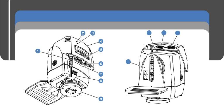
Components and Connections
Front View |
|
Rear View |
11 |
12 |
13 |
10
1 . . . . . . . . . . . . . . . . . . . . . . Power cable with IEC connector 2 . . . . . . . . . . . . . . . . . . . . . . . . . . . . . . . . . . . . . . . Data LED 3 . . . . . . . . . . . . . . . . . . . . . . . . . . . . . . . . . . . . . Genlock LED 4 . . . . . . . . . . . . . . . . . . . . . . . . . . . . . . . . . . . . . . . Top cover 5 . . . . . . . . . . . . . . . . . . . . . . . . . . . . . . . . . . . . . . Service port 6 . . . . . . . . . . . . . . . . . . . . . . . . . . . . . . . . . . . . . Ethernet port 7 . . . . . . . . . . . . . . . . . . . . . . . . . . . . . . . . . . Network ID label 8 . . . . . . . . . . . . . . . . . . . . . . . . . Cable management bracket 9 . . . . . . . . . . . . . . . . . . . . . . . . . . . . . . . . . . . Mounting plate
10 . . . . . . . . . . . . . . . . . . . . . . . . . . . . . . . . . . . Camera cradle 11 . . . . . . . . . . . . . . . . . . . . . . . . . . . . . . . . . . . . . . . . . Tilt lock 12 . . . . . . . . . . . . . . . . . . . . . . . . . General purpose connector 13 . . . . . . . . . . . . . . . . . . . . . . . . . . . Lens interface connector
4
FHR-35 Robotic Pan and Tilt Head
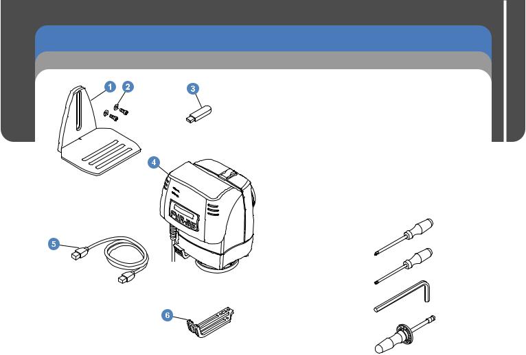
Installation
Box Contents and Tools Required
1 . . . . . . . . . . . . . . . . . . . . . . . . . . . . . . . . . . . . Camera cradle 2. . . . . . . . . . . . . . . . . . . . . . . . . . Cradle screws and washers 3 . . . . . . . . . . . . . . . . . . . . . . . . . . . . . . . . . . . . . . . . USB stick 4 . . . . . . . . . . . . . . . . . . . . . FHR-35 Robotic pan and tilt head
5 . . . . . . . . . . . . . . . . . . . . . . . . . . . . . . . . . . . . Ethernet cable 6 . . . . . . . . . . . . . . . . . . . . . Large cable management bracket NI . . . . . . . . . . . . . . . . . . Installation and Configuration Guide
NI. . . . . . . . . . . . . . . . . . . . . . . . . . . . . . . . Quick Setup Guide
NI . . . . . . . . . . . . . . . . . . . . . . . . . . . . . . . . . . . . Cable ties x5 NI . . . . . 10-32 U x .625 in. pan head screws and washers x6 NI . . . . . . . . . . . . . M6 x 16 cap head screws and washers x4
NI . . . . . . . 3/8" BSW x 3/4" cap head screws and washers x2
NI = Not Illustrated
Tools required
Pozidriv® PZ-1 screwdriver
Torx® T10 screwdriver
4 mm Allen key
5 mm Allen key 5/16" Allen key 5/32" Allen key
Torque screwdriver
Installation and Configuration Guide
5

Installation and Configuration Guide
FHR-35 Robotic Pan and Tilt Head
Installation
Mounting Supports and Adaptors
NO. |
MOUNTING |
PART NO. |
MOUNT |
|
SUPPORT OR |
|
OPTION |
|
ADAPTOR |
|
|
1 |
VMA plate |
AM-VMA-105 |
HD tripod |
2 |
Wall mounting |
AM-WBKT-102 |
Wall |
|
bracket |
|
|
3 |
Ceiling mounting |
AM-CEIL-102 |
Ceiling |
|
bracket |
|
|
4 |
Adaptor with |
V4096-1013 |
Pozi Loc tripod |
|
Quickfix groove |
|
HD tripod |
5 |
Quickfix adaptor |
3490-3 |
HD tripod |
6 |
Radamec |
196-728-0044 |
Ceiling |
|
adaptor column |
|
Pozi Loc tripod |
7 |
150 mm bowl |
3104-3 |
Pozi Loc tripod |
|
adaptor |
|
|
8 |
Quickfix 150 mm |
3143-3 |
Pozi Loc tripod |
|
bowl adaptor |
|
|
6

FHR-35 Robotic Pan and Tilt Head
Installation
Cable Management Brackets |
Removing the Camera Cradle |
The FHR-35 is supplied with a cable management bracket fitted to the base. Camera and head connecting cables can be neatly secured to the bracket providing strain relief for the connectors. Depending on the camera and head setup, the larger cable management bracket can be fitted.
V4096-2075
Supplied fitted to the head
V4096-2082
The first step in installing the head is to set the mechanical hard stops to limit the movement of the head about the pan and tilt axes. To set these limits, the camera cradle must be removed.
1. Using a 4 mm Allen key, remove the two screws and washers securing the camera cradle.
2. Pull the camera cradle away from the tilt mounting plate.
Installation and Configuration Guide
7

Installation and Configuration Guide
FHR-35 Robotic Pan and Tilt Head
Installation
Setting the Pan and Tilt Mechanical Hard Stops
The FHR-35 is fitted with adjustable mechanical hard stops that safely restrict the range of movement about the pan and tilt axes. The pan and tilt mountings have a fixed stop and two adjustable stop rings that are locked at the required maximum and minimum limits of movement.
Setting the pan and tilt mechanical hard stops ensures that:
-The head and payload cannot collide with any fixed objects within the working robotic footprint of the head.
-The payload will not collide with the head or the mounting bracket or support.
-Undesirable areas of the studio are kept out of shot.
When the mechanical hard stops are locked in position, the head will not be able to drive beyond them. However, the head is still able to drive and collide into the mechanical hard stops. To prevent this, soft limits are programmed into the head at points within the range of the mechanical hard stops. This eliminates the risk of constant collision with the mechanical hard stops, and also restricts the head’s movement range further whenever necessary. See the section Setting the Zero Position and Soft Limits for more details.
1 |
.......................Tilt fixed stop |
2....................... |
Tilt stop rings |
3...................... |
Pan fixed stop |
4...................... |
Pan stop rings |
8

1.(a) Place the camera cradle over the tilt mounting. Move the tilt mounting in a clockwise direction to the required maximum limit of movement.
(b) Remove the camera cradle. Move the large outer ring clockwise until it rests on the fixed stop.
(c) Secure the grub screw into position using a
2.5 mm Allen key. Tighten the screw to a minimum of 1.5 Nm (13.3 lbf-in.).
2.(a) Place the camera cradle over the tilt mounting. Move the tilt mounting in a counterclockwise direction to the required minimum limit of movement.
(b) Remove the camera cradle. Move the inner ring clockwise until it rests on the large outer ring stop.
(c) Secure the grub screw into position using a 2.5 mm Allen key. Tighten the screw to a minimum of
1.5 Nm (13.3 lbf-in.).
FHR-35 Robotic Pan and Tilt Head |
Guide |
Installation |
ConfigurationandInstallation |
|
|
Setting the Tilt Mechanical Hard Stops |
|
a |
b |
c |
a |
b |
c |
9
 Loading...