


Installation Manual V1.4.4

Vinten Broadcast Ltd |
free-d™ Installation Manual V1.4.4 |
|
|
Vinten Broadcast Ltd |
Vinten Inc |
Western Way |
709 Executive Blvd. |
Bury St Edmunds |
Valley Cottage |
Suffolk |
NY 10989 |
IP33 3TB |
USA |
United Kingdom |
|
Tel: +44 1284 752121 |
Tel: (845) 268 0100 |
Fax: +44 1284 750560 |
Fax: (845) 268 0113 |
|
Email: info@vinten.com |
Compiled by: |
James Oliver - Product Manager |
|
|
Issue Date: |
April 2004 |
Copyright © Vinten Broadcast Limited 2004
The copyright in this document is vested in Vinten Broadcast Ltd, part of the Vitec Group. This document is issued in confidence solely for the purpose for which it is supplied. Reproduction in whole or in part, or the use of this document for tendering or manufacturing purposes is prohibited, except under an agreement or with the written consent of the company of origin, and then only on the condition that this notice is included in any such reproduction.
'Vinten Radamec Broadcast Robotics' and 'free-d' are registered trademarks of Vinten Broadcast Limited.
Page 2 of 46

Vinten Broadcast Ltd free-d™ Installation Manual V1.4.4
Table of contents
1 |
Introduction |
|
4 |
|
|
1.1 |
Virtual sets |
4 |
|
|
1.2 |
free-d™ |
|
4 |
2 |
System components |
5 |
||
3 |
Installation |
|
6 |
|
|
3.1 |
Targets |
|
6 |
|
3.2 |
Lens encoder |
6 |
|
|
3.3 |
Target seeking camera |
8 |
|
|
3.4 |
free-d™ |
Processor unit |
8 |
4 |
Interconnection |
10 |
||
5 |
Camera optimisation |
11 |
||
6 |
Calibration procedure |
13 |
||
|
6.1 |
Constructing a target database |
14 |
|
|
6.2 |
Free-d calibration wizard |
16 |
|
|
|
6.2.1 |
Studio list |
16 |
|
|
6.2.2 |
Camera list |
17 |
|
|
6.2.3 |
Interfaces |
18 |
|
6.3 |
Additional free-d™ Processors |
20 |
|
|
6.4 |
Additional free-d™ Target seeking cameras |
21 |
|
7 |
System verification |
22 |
||
|
7.1 |
RMS error |
22 |
|
|
7.2 |
Levelling |
22 |
|
|
7.3 |
Scale |
|
22 |
|
7.4 |
Height and camera Z-offset |
23 |
|
|
7.5 |
Camera x-offset |
23 |
|
|
7.6 |
CCD centering |
24 |
|
|
7.7 |
Video delay |
24 |
|
|
7.8 |
Horizontal view angle |
24 |
|
|
7.9 |
Vertical view angle and aspect ratio |
25 |
|
|
7.10 |
Nodal shift and camera Y-offset |
25 |
|
|
7.11 |
Pan adjustment |
26 |
|
|
7.12 |
Tilt adjustment |
26 |
|
|
7.13 |
Roll adjustment |
27 |
|
Appendices |
|
|
28 |
|
|
A - |
free-d™ |
Communications protocol v1.0 |
28 |
|
B - |
Camera positioning parameters |
40 |
|
|
C - |
free-d™ processor card settings and warnings |
43 |
|
|
D - |
free-d™ Target seeking camera ID settings |
45 |
|
|
E - |
free-d™ Target seeking camera exposure settings |
45 |
|
|
F - |
Typical system schematic and part numbers |
45 |
|
|
G - |
Target array template diagram |
46 |
|
Page 3 of 46

Vinten Broadcast Ltd |
free-d™ Installation Manual V1.4.4 |
|
|
1 Introduction
1.1Virtual sets
A key component of any virtual studio system is a means of measuring the precise position and orientation of each studio camera. This data is used to render the virtual scene from the appropriate viewpoint.
A camera tracking system must allow unrestricted movement of many studio cameras while panning through 360 degrees, work with a wide variety of camera mountings including manual pedestals, cranes, and hand-held cameras. The measurement of position and orientation of the camera must be to an accuracy that ensures precise matching of the real and virtual worlds.
It should place no significant constraints on either the scene content or the studio environment. free-d™ satisfies all of these requirements.
1.2free-d™
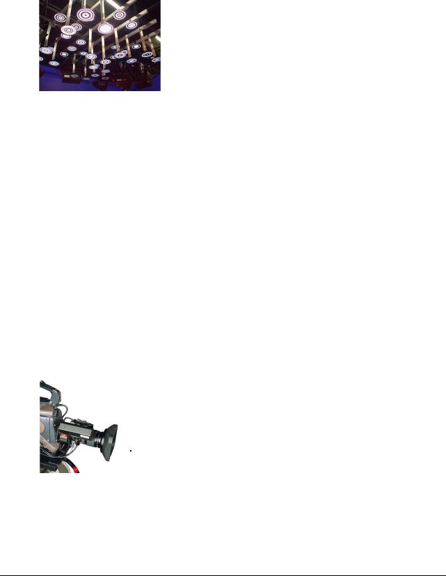
Developed by BBC R&D, this system uses a number of targets placed out of shot above the studio lighting grid. The targets are composed of concentric black and white retro-reflective rings forming a type of barcode. Each target has a unique code number, and is mounted at one of two different heights for optimum performance.
A small Target Seeking Camera (TSC) mounted on each studio camera views these targets. The TSC is mounted rigidly with its optical axis at right angles to the optical axis of the studio camera. A ring of LEDs surrounds the lens of the TSC. They illuminate the retro-reflective ceiling mounted targets.
The data from the TSC is passed to a purpose-built hardware unit, (free-d™ processor) which calculates the precise position and orientation of the studio camera in real time. free-d™ identifies the targets, measures their position to sub-pixel accuracy, and reads their barcodes. The position and orientation of the camera can then be computed.
The studio camera’s zoom and focus are measured using conventional mechanical sensors. These data are multiplexed with the signal from the auxiliary camera. free-d™ outputs an RS422 signal that contains camera X, Y, height, pan, tilt, roll, zoom and focus data. Using this data output, the virtual set system will then create a background very accurately matching the position of the real camera, to within 1mm.
Page 4 of 46

Vinten Broadcast Ltd |
free-d™ Installation Manual V1.4.4 |
|
|
2 System components
Supplied items:
|
Part Number |
|
Description |
|
|
|
|
|
101-072-0002 |
|
free-d™ Target Seeking Camera (TSC) |
|
|
|
|
|
Various |
|
Camera adapter bracket (to attach TSC to studio |
|
|
|
camera) |
|
|
|
|
|
012-037-0020 |
|
TSC power cable (standard length 20m) |
|
|
|
|
|
195-112-0002 |
|
TSC power supply |
|
|
|
|
|
177-072-0001 |
|
free-d™ Processor |
|
|
|
|
|
Various |
|
Lens encoder |
|
|
|
|
|
N/A |
|
Mains cables (2 per camera system) |
|
|
|
|
|
Various |
|
Upper and lower targets (of roughly equal quantity) |
|
|
|
|
|
N/A |
|
3.5 inch floppy disk containing free-d™ lens calibration |
|
|
|
|
Required items not supplied:
∙Genlock source (if Free-d unit is not polled by VR system)
∙Genlock video cable
∙TSC video cable (length as required)
∙Oscilloscope (for calibration purposes only)
∙NTSC composite video monitor (for calibration purposes only)
∙PC laptop* (for calibration purposes only)
∙RS422/232 converter* (for calibration purposes only)
∙9 way pin-to-pin D-type serial cable* (for calibration purposes only)
Note: items marked with * will be provided by the Vinten Radamec Engineer for the duration of the on-site system commissioning.
Page 5 of 46
Vinten Broadcast Ltd |
free-d™ Installation Manual V1.4.4 |
|
|
3Installation
3.1 Targets
The targets supplied will come with drop rods, but not necessarily horizontal mounting bars. It is normally required that the customer or system integrator source and supply these bars and a means to mount the bars to the ceiling. A dedicated grid is the best method of securing the target bars. It is essential that whatever method is employed, the target array must be secure and vibration free.
The optimum pattern of high and low targets can be seen in Appendix G. This is an optimum pattern only; it is designed so that the maximum number of targets will be identified, with the minimum number of low targets obscuring high targets. For ease of installation and calibration, this pattern should be observed while installing the targets on the studio ceiling.
However, if there are any obstructions in the ceiling preventing the mounting of a high target (eg, ducting, air-conditioning units) then a low target will suffice.
The major objective when installing targets is to ensure that a roughly equal number of high and low targets can be seen by the Target Seeking Camera in any position in the studio.
The optimum distance between each target is studio height dependent, and will be advised by the Vinten Radamec Project Manager.
Whilst installing the targets, note the identification number located on the back of the target on the target map. This will significantly expedite the calibration process.
3.2 Lens encoder
|
|
Single module dimensions |
136mm x 45mm x 70mm |
Weight (pair) |
1 kg approx. |
Encoders to lens gearing |
24 : 1 |
Output signals |
1024 pulses / rev of encoder |
Electrical connection |
1m flying lead to 26 way 'D' |
|
type. |
Always fit the protective cap to the studio lens during installation of the encoder. Remove the two screws that secure the cover of the drive module. Lift the cover off.
Page 6 of 46

Vinten Broadcast Ltd |
free-d™ Installation Manual V1.4.4 |
|
|
Remove the two hex-socket screws that secure the module to the mounting block adapter plate. Take care not to damage any internal components when removing the module. Slacken the two screws that fasten the focus section to the zoom section.
Remove the two screws and lock washers from the mounting block, then fit the block to the lens. Do not over tighten the mounting screws. Check that both zoom and focus elements are not obstructed and move freely after fitting the mounting block.
CAUTION
IT IS ESSENTIAL THAT ONLY THE SCREWS AND WASHERS SUPPLIED ARE USED.
INCORRECT LENGTH SCREWS CAN PERMANENTLY DAMAGE THE LENS.
Fit the module in position the mounting block with the zoom section in mesh with the zoom gear ring of the lens and estimate how far its gear is out of mesh with the zoom gear ring. Remove the module and extract the spacer shim from between the adapter plate and the mounting block. Peel off an amount from the spacer (each shim is 0.05 mm, 0.002 inch thick) that is equal to, or less than, the amount estimated to bring the gears into mesh. Re-fit the module and repeat the procedure until the gears mesh correctly.
NOTE
CORRECT MESH IS VERY IMPORTANT AS TIGHT SPOTS WILL RESULT IN POOR PERFORMANCE.
Check the mesh at several points while rotating the lens gear ring from end to end and ensure that a small amount of backlash can just be felt at the tightest point.
Adjust the mesh of the focus section with the focus gear ring of the lens and tighten the two screws that fix it to the zoom section. Check the mesh at several points whilst rotating the focus gear ring from end to end and ensure that a small amount of backlash can just be felt at the tightest point. Readjust the focus mesh until this is satisfactory.
Do not lubricate the output gear/lens ring. Check end-to-end operation of both zoom and focus. When satisfactory, re-fit the encoder module cover.
Page 7 of 46

Vinten Broadcast Ltd |
free-d™ Installation Manual V1.4.4 |
||
|
|
|
|
3.3 Target seeking camera |
|
|
|
|
|
|
|
|
|
|
|
|
Dimensions |
100mm x 82mm x 82mm |
|
|
Weight |
1.5 kg |
|
|
Lens |
Pentax, Ref. C30811 (C-mount) |
|
|
Output signals |
Serial digital video (NTSC) |
|
|
|
|
|
|
Connectors |
BNC – video output |
|
|
|
BNC – genlock input |
|
|
|
26w ‘D’ – Lens encoder input |
|
|
|
2x9w ‘D’ – Power Input |
|
|
|
15w ‘D’ – RBU input |
|
The Target Seeking Camera (TSC) is intended to mount rigidly to a studio camera, perpendicular to the optical axis. It will normally mount in place of the viewfinder, either above the lens at the front of the camera or at the rear if hand-held operation is required. Custom-designed mounting brackets are normally supplied to suit the cameras in the studio. The base of the TSC can be adjusted to ensure that is as near as possible to perpendicular to the studio camera optical axis.
The view of the targets should be unobstructed (for example by any part of the camera operator’s body) and should not make operating the studio cumbersome or make it difficult to balance. The offset between the two cameras must be known so that the system can compensate during calibration.
The TSC will need to be genlocked if the virtual set system software is not polling the free-d™ processor. Contact your virtual set vendor for verification.
3.4 free-d™ Processor unit
|
|
Dimensions |
483mm x 43mm x 500mm |
|
(19inch, 1U, 500mm) |
Weight |
8.5 kg approx. |
Input signals |
Serial digital video, |
|
RS422/RS485 control data |
Output |
Analogue video, |
signals |
RS422/RS485 camera data |
|
System normal relay |
Power Supply |
85 to 265 volts AC, 47 – 440 Hz, 5A |
The free-d™ Processor Unit receives a serial digital video signal from the TSC which contains both the image of the targets as viewed by the auxiliary camera
Page 8 of 46

Vinten Broadcast Ltd |
free-d™ Installation Manual V1.4.4 |
|
|
and encoded values of the zoom and focus (which are measured by conventional mechanical sensors). The 19 inch rack-mountable unit identifies the targets in the image, measures their positions to sub-pixel accuracy and reads their bar codes. Knowing the positions of each target in the studio, which are stored in non-volatile memory, the position and orientation of the camera can be computed.
The unit generates an RS422/RS485 serial data stream, which conveys the position, orientation, zoom, and focus data to the virtual set system.
There is a BNC connection available to monitor the operation of the TSC. Monitoring of this NTSC signal will be required during calibration.
On initial installation the default control parameters should be loaded into the free-d™ Processor Unit. This can be achieved by operating the card switches in the following sequence: Hold RESET (S1), hold STORE (S4), release RESET, wait until self-tests are complete, release STORE. The default parameters may then be stored in the unit's non-volatile memory by another operation of the STORE switch.
Page 9 of 46
Vinten Broadcast Ltd |
free-d™ Installation Manual V1.4.4 |
|
|
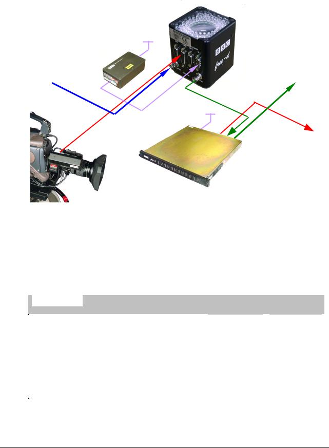
4 Interconnection
Target Seeking Camera TSC
110/230Vac
TSC PSU
Genlock
NTSC Monitor Video
Input 24Vdc (if required)
TSC Video
110/230Vac
Lens encoder data |
RS-422 |
|
To VR System |
||
|
Free-d Processor Unit
Cables indicated by a dotted line are not supplied with the Free-d system.
When connecting the free-d™ processor to the calibration PC, an RS-422/232 converter will be required and a direct, pin-to-pin cable, 9-way male D-type to
9-way male D-type. The SDL cable to connect the free-d™ processor to an
Onyx, Onyx2, Xync interface or Virtual Scenario SCU should be made as follows:
|
free-d™ |
|
Onyx |
Onyx2 |
Xync |
Virtual |
|
|
|
|
|
Interface |
Scenario |
|
9-way male |
|
9-way female |
9-way female |
25-way female |
9-way male |
|
D-type |
|
D-type |
D-type |
D-type |
D-type |
|
2 Tx- |
|
2 Rx- |
2 Rx- |
15 Rx- |
5 Rx- |
|
8 Rx- |
|
3 Tx- |
3 Tx- |
14 Tx- |
9 Tx- |
|
3 Rx+ |
|
7 Tx+ |
4 Tx+ |
2 Tx+ |
8 Tx+ |
|
7 Tx+ |
|
8 Rx+ |
6 Rx+ |
3 Rx+ |
4 Rx+ |
|
|
|
|
|
|
|
Page 10 of 46
Vinten Broadcast Ltd |
free-d™ Installation Manual V1.4.4 |
|
|
5 Camera optimisation
LED array
|
|
|
S103 Test purposes |
Focus – take |
|
|
|
care not to |
|
|
|
disturb |
|
|
|
|
|
|
S102 Exposure time |
|
|
|
|
|
|
|
control |
Gain levels – |
|
|
|
|
|
||
factory set |
|
|
|
|
|
|
|
|
|
|
S101 Camera ID |
Iris |
|
|
Number |
|
|
|
|
|
|
|
|
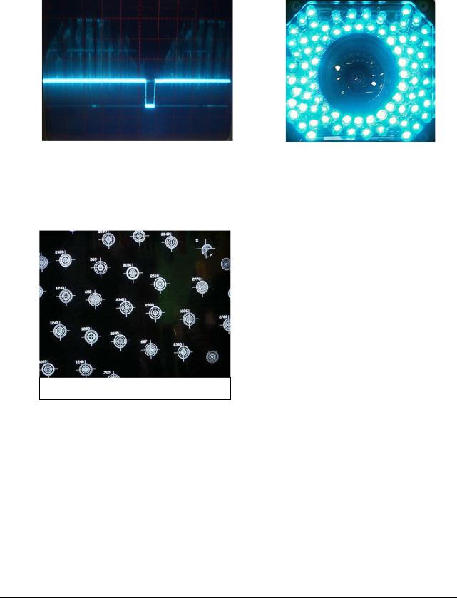
Set the camera ID number using rotary switch S101 (see Appendix D). Place the free-d™ TSC at its lowest operating height (in most cases this will be with the studio camera on the floor) so that it has an unobstructed view of the targets. Switch off any house lights in the field of view of the camera.
Observe the monitoring video output from the free-d™ Processor on both a picture monitor and on an oscilloscope triggered at TV line rate. The video level of the brightest targets should be close to peak white (0.7 Volt) but without any clipping. If this is not the case, it will be necessary to adjust the iris of the free-d™ TSC; take extreme care not to disturb the focus.
Optimised – uniform amplitude, no clipping
Clipping – bright peaks indicate video level saturation
Check on both the NTSC monitor and the oscilloscope that all the targets in view have approximately the same video level (the dimmest target should
Page 11 of 46
Vinten Broadcast Ltd |
free-d™ Installation Manual V1.4.4 |
|
|
have a video level no less than 70% that of the brightest target). If the brightness is less uniform than this, it will be necessary to adjust the ‘aiming’ of the illuminating LEDs.
Badly aimed LEDs – centre targets |
|
free-d™ TSC top-view |
brighter than outer targets. |
|
LEDs after aiming. |
|
|
|
Check that most of the targets that can be seen in the image are being recognised by the system and are annotated with their barcode numbers.
If any target barcode values are missing (or are replaced with a x or + symbol), and there is no obvious reason such as the target being partially obscured or damaged, suspect that the focus is not correctly set for the studio height. If it is necessary to change the focus, even slightly, it is essential that the free-d™ camera be re-calibrated afterwards.
free-d™ Processor monitor output
To maximise the depth-of-field, ensure that the exposure-time control (S102) is set to position ‘D’; this is the position wherethe LED array appears to be brightest.
If high-speed camera movements are anticipated, it may be desirable to reduce the exposure time. See appendix E.
Page 12 of 46
Vinten Broadcast Ltd |
free-d™ Installation Manual V1.4.4 |
|
|
6 Calibration procedure
Before proceeding, ensure that all required targets have been mounted in the studio ceiling and the identification number of each target number noted onto the map (see Appendix G). If no target map is available, it will have to be reconstructed by directing the Free-d camera at the target array, and reading the target ID numbers from a monitor connected to the monitor output of the processor.
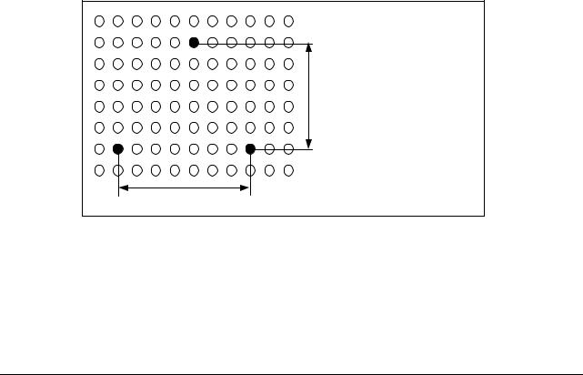
Select a suitable studio reference point. This reference (or zero) is typically the bottom left target on the target map (Row1, Column 1). In actuality the reference point can be any permanent reference in the studio. If there is a 3D virtual set system already in operation in the studio then it may be more convenient to use the same reference as the VR set.
Measure three targets with respect to the reference. It is essential that these targets be measured to the best accuracy possible, as the results have a huge effect on the subsequent calibration. It is necessary to measure x, y, and height of two targets (A and B) and height only of a third target (C). The distance between targets A and B should be greater than 50% of the entire target array in the x-axis. This determines a baseline from which all other targets are measured. The distance from target C to the baseline should be greater than 50% of the entire length of the y-axis. If these rules are not adhered to, the Calibration Wizard will not proceed and the program will display a warning. The measured targets do not have to be on different rows or columns, and they do not have to be at different heights.
C
|
|
|
Measure: |
|
|
>50% |
A = x, y and height |
|
|
|
|
|
|
|
B = x, y and height |
A |
B |
|
C = height only |
>50%
Note these measurements together with their ID number. These ID numbers will be entered in the calibration program (freed_v14.exe).
Page 13 of 46
Vinten Broadcast Ltd |
free-d™ Installation Manual V1.4.4 |
|
|
6.1Constructing a target database
Once operational, the system must know the exact position of every target to an accuracy of less than 1mm. To measure every single target to this level of accuracy, while not impossible, would be difficult and time consuming. The calibration process is able to refine the target positions provided an initial accuracy of 100 mm is achieved.
Provided the precise position of the three measured targets is determined, the system will refine the position of all the others.
Run the program makedef.exe. This creates a text file containing x,y,z values based on the installed grid pattern. When prompted input the x, y spacing and number of targets for each direction, height of upper and lower targets, min x and y values from origin (an offset of x, y, normally 0.0 for each) and the pattern of high and low targets used.
The pattern is defined by a hex word. The whole pattern can be calculated by knowing the configuration of the first block of 16 targets (4x4) situated in the bottom right-hand corner of the target map.
|
|
|
|
|
|
|
|
Row 4 |
Low = 0 |
Low = 0 |
High = 1 |
High = 1 |
|
= 3 in Hex |
|
Row 3 |
High = 1 |
Low = 0 |
Low = 0 |
High = 1 |
|
= 9 in Hex |
|
Row 2 |
Low = 0 |
Low = 0 |
High = 1 |
High = 1 |
|
= 3 in Hex |
|
Row 1 |
Low = 0 |
High = 1 |
High = 1 |
Low = 0 |
|
= 6 in Hex |
|
|
Col 1 |
Col 2 |
Col 3 |
Col 4 |
|
Byte Word = 6393 |
|
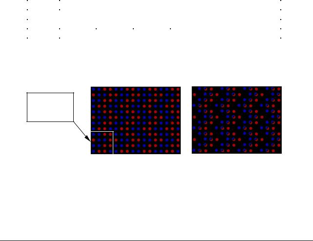
To view and check the pattern byte word, run the program seepatt.exe and enter the pattern to be used in hex (in this case 6393). Blue = Low, Red = High.
This portion should match the 16 target block above.
Target pattern hex “6393” |
Tilt/roll simulation |
Use the cursor keys to simulate tilt and roll of the camera to see the extent of low targets obscuring high targets.
Page 14 of 46
 Loading...