


 Loading...
VRC Vinten Radamec Control System v1.3.3
VRC
Vinten Radamec Control
System v1.3.3
Operators Guide
Part No. V4009-8001
www.vintenradamec.com
Vinten Radamec
Control (VRC) System
User Guide
Version 1.3.3
Publication No. V4009-4980 Issue 6
Copyright © 2012
All rights reserved.
Original Instructions: English
All rights reserved throughout the world. No part of this document may be stored in a retrieval system, transmitted, copied or reproduced in any way, including, but not limited to, photocopy, photograph, magnetic or other record without the prior agreement and permission in writing of the Vitec Group plc.
Disclaimer
The information contained in this manual is believed to be correct at the time of printing. Vitec Videocom Ltd reserves the right to make changes to the information or specifications without obligation to notify any person of such revision or changes. Changes will be incorporated in new versions of the publication.
We are making every effort to ensure that our manuals are updated on a regular basis to reflect changes to product specifications and features. Should this manual not contain information on the core functionality of your product, please let us know. You may be able to access the latest revision of this manual from our website.
Vitec Videocom Ltd. reserves the right to make changes to product design and functionality without notification.
Trademarks
All product trademarks and registered trademarks are the property of the Vitec Group plc.
All other trademarks and registered trademarks are the property of their respective companies.
Published by:
Vitec Videocom Ltd
Supports Technical Publications Department
Western Way
Bury St Edmunds
Suffolk IP33 3TB
United Kingdom
Email: technical.publications@vitecgroup.com

Contents
Getting Started . . . . . . . . . . . . . . . . . . . . . . . . . . . . . . . . . . . . . . . . . . . . . . . . . . . . . . . . . . . . 7
System overview . . . . . . . . . . . . . . . . . . . . . . . . . . . . . . . . . . . . . . . . . . . . . . . . . . . . . . . . 7
Starting the VRC software . . . . . . . . . . . . . . . . . . . . . . . . . . . . . . . . . . . . . . . . . . . . . . . . . 8 Starting the VRC EPI server . . . . . . . . . . . . . . . . . . . . . . . . . . . . . . . . . . . . . . . . . . . . 9 Starting the VRC Client application . . . . . . . . . . . . . . . . . . . . . . . . . . . . . . . . . . . . . . 10 Calibrating the touch screen . . . . . . . . . . . . . . . . . . . . . . . . . . . . . . . . . . . . . . . . . . . 11 Automation Interface . . . . . . . . . . . . . . . . . . . . . . . . . . . . . . . . . . . . . . . . . . . . . . . . . 12
VRC Control Panel . . . . . . . . . . . . . . . . . . . . . . . . . . . . . . . . . . . . . . . . . . . . . . . . . . . . . . . . 13
Overview . . . . . . . . . . . . . . . . . . . . . . . . . . . . . . . . . . . . . . . . . . . . . . . . . . . . . . . . . . . . . 13 Switching on the panel . . . . . . . . . . . . . . . . . . . . . . . . . . . . . . . . . . . . . . . . . . . . . . . 15 Configuring the operation of the control panel. . . . . . . . . . . . . . . . . . . . . . . . . . . . . . 15 Tally Indicators . . . . . . . . . . . . . . . . . . . . . . . . . . . . . . . . . . . . . . . . . . . . . . . . . . . . . 15 Locking the control panel. . . . . . . . . . . . . . . . . . . . . . . . . . . . . . . . . . . . . . . . . . . . . . 15
Controlling a camera unit . . . . . . . . . . . . . . . . . . . . . . . . . . . . . . . . . . . . . . . . . . . . . . . . . 16 Selecting a camera . . . . . . . . . . . . . . . . . . . . . . . . . . . . . . . . . . . . . . . . . . . . . . . . . . 16 Button mapping . . . . . . . . . . . . . . . . . . . . . . . . . . . . . . . . . . . . . . . . . . . . . . . . . . . . . 16 Pan/Tilt/Zoom joystick . . . . . . . . . . . . . . . . . . . . . . . . . . . . . . . . . . . . . . . . . . . . . . . . 17 Focus control . . . . . . . . . . . . . . . . . . . . . . . . . . . . . . . . . . . . . . . . . . . . . . . . . . . . . . . 17 Black level and Iris CCU controls . . . . . . . . . . . . . . . . . . . . . . . . . . . . . . . . . . . . . . . 17 Wash wipe . . . . . . . . . . . . . . . . . . . . . . . . . . . . . . . . . . . . . . . . . . . . . . . . . . . . . . . . . 17 X4 . . . . . . . . . . . . . . . . . . . . . . . . . . . . . . . . . . . . . . . . . . . . . . . . . . . . . . . . . . . . . . . 17
Remote pedestal operation . . . . . . . . . . . . . . . . . . . . . . . . . . . . . . . . . . . . . . . . . . . . . . . 18 Pedestal orientation. . . . . . . . . . . . . . . . . . . . . . . . . . . . . . . . . . . . . . . . . . . . . . . . . . 18 Joystick enable . . . . . . . . . . . . . . . . . . . . . . . . . . . . . . . . . . . . . . . . . . . . . . . . . . . . . 18 XY/Height joystick . . . . . . . . . . . . . . . . . . . . . . . . . . . . . . . . . . . . . . . . . . . . . . . . . . . 19 Pan follow . . . . . . . . . . . . . . . . . . . . . . . . . . . . . . . . . . . . . . . . . . . . . . . . . . . . . . . . . 19 Bumper disable . . . . . . . . . . . . . . . . . . . . . . . . . . . . . . . . . . . . . . . . . . . . . . . . . . . . . 19 RP2A control functions . . . . . . . . . . . . . . . . . . . . . . . . . . . . . . . . . . . . . . . . . . . . . . . 20
VRC Client User Interface . . . . . . . . . . . . . . . . . . . . . . . . . . . . . . . . . . . . . . . . . . . . . . . . . . . 21
Client workspace . . . . . . . . . . . . . . . . . . . . . . . . . . . . . . . . . . . . . . . . . . . . . . . . . . . . . . . 21 Title bar . . . . . . . . . . . . . . . . . . . . . . . . . . . . . . . . . . . . . . . . . . . . . . . . . . . . . . . . . . . 22 Primary Panel Groups bar . . . . . . . . . . . . . . . . . . . . . . . . . . . . . . . . . . . . . . . . . . . . . 22 Preview Panel Groups bar. . . . . . . . . . . . . . . . . . . . . . . . . . . . . . . . . . . . . . . . . . . . . 23 Stored shot editing grid . . . . . . . . . . . . . . . . . . . . . . . . . . . . . . . . . . . . . . . . . . . . . . . 23 Camera selection and status bar. . . . . . . . . . . . . . . . . . . . . . . . . . . . . . . . . . . . . . . . 25
Function buttons and menus . . . . . . . . . . . . . . . . . . . . . . . . . . . . . . . . . . . . . . . . . . . . . . 28 Toolbar Menu . . . . . . . . . . . . . . . . . . . . . . . . . . . . . . . . . . . . . . . . . . . . . . . . . . . . . . 30 Edit menu . . . . . . . . . . . . . . . . . . . . . . . . . . . . . . . . . . . . . . . . . . . . . . . . . . . . . . . . . 31 Stop . . . . . . . . . . . . . . . . . . . . . . . . . . . . . . . . . . . . . . . . . . . . . . . . . . . . . . . . . . . . . . 31 Cut . . . . . . . . . . . . . . . . . . . . . . . . . . . . . . . . . . . . . . . . . . . . . . . . . . . . . . . . . . . . . . . 32 Fade . . . . . . . . . . . . . . . . . . . . . . . . . . . . . . . . . . . . . . . . . . . . . . . . . . . . . . . . . . . . . 32 Fade or Cut multiple shots. . . . . . . . . . . . . . . . . . . . . . . . . . . . . . . . . . . . . . . . . . . . . 32 Store . . . . . . . . . . . . . . . . . . . . . . . . . . . . . . . . . . . . . . . . . . . . . . . . . . . . . . . . . . . . . 33 Focus. . . . . . . . . . . . . . . . . . . . . . . . . . . . . . . . . . . . . . . . . . . . . . . . . . . . . . . . . . . . . 33 Virtual joystick controls . . . . . . . . . . . . . . . . . . . . . . . . . . . . . . . . . . . . . . . . . . . . . . . 34 Opts menu . . . . . . . . . . . . . . . . . . . . . . . . . . . . . . . . . . . . . . . . . . . . . . . . . . . . . . . . . 35
3

VRC System User Guide
Shots and Shows . . . . . . . . . . . . . . . . . . . . . . . . . . . . . . . . . . . . . . . . . . . . . . . . . . . . . . . . . 37
Show management . . . . . . . . . . . . . . . . . . . . . . . . . . . . . . . . . . . . . . . . . . . . . . . . . . . . . 37
Creating a new show . . . . . . . . . . . . . . . . . . . . . . . . . . . . . . . . . . . . . . . . . . . . . . . . . 38
Loading a show . . . . . . . . . . . . . . . . . . . . . . . . . . . . . . . . . . . . . . . . . . . . . . . . . . . . . 38
Listing all shows . . . . . . . . . . . . . . . . . . . . . . . . . . . . . . . . . . . . . . . . . . . . . . . . . . . . 38
Deleting a show . . . . . . . . . . . . . . . . . . . . . . . . . . . . . . . . . . . . . . . . . . . . . . . . . . . . . 39
Creating Home or Target shots . . . . . . . . . . . . . . . . . . . . . . . . . . . . . . . . . . . . . . . . . . . . 39
Adding shots to a show . . . . . . . . . . . . . . . . . . . . . . . . . . . . . . . . . . . . . . . . . . . . . . . . . . 41
Managing shots . . . . . . . . . . . . . . . . . . . . . . . . . . . . . . . . . . . . . . . . . . . . . . . . . . . . . . . . 41
Latched Delete . . . . . . . . . . . . . . . . . . . . . . . . . . . . . . . . . . . . . . . . . . . . . . . . . . . . . 42
Latched Time. . . . . . . . . . . . . . . . . . . . . . . . . . . . . . . . . . . . . . . . . . . . . . . . . . . . . . . 42
Name . . . . . . . . . . . . . . . . . . . . . . . . . . . . . . . . . . . . . . . . . . . . . . . . . . . . . . . . . . . . . 43
Time. . . . . . . . . . . . . . . . . . . . . . . . . . . . . . . . . . . . . . . . . . . . . . . . . . . . . . . . . . . . . . 43
Delete . . . . . . . . . . . . . . . . . . . . . . . . . . . . . . . . . . . . . . . . . . . . . . . . . . . . . . . . . . . . 43
Resave . . . . . . . . . . . . . . . . . . . . . . . . . . . . . . . . . . . . . . . . . . . . . . . . . . . . . . . . . . . 43
Swap . . . . . . . . . . . . . . . . . . . . . . . . . . . . . . . . . . . . . . . . . . . . . . . . . . . . . . . . . . . . . 44
Return . . . . . . . . . . . . . . . . . . . . . . . . . . . . . . . . . . . . . . . . . . . . . . . . . . . . . . . . . . . . 44
Running a Show . . . . . . . . . . . . . . . . . . . . . . . . . . . . . . . . . . . . . . . . . . . . . . . . . . . . . . . . . . 45
Cueing shots . . . . . . . . . . . . . . . . . . . . . . . . . . . . . . . . . . . . . . . . . . . . . . . . . . . . . . . . . . 45 Shot control sequence. . . . . . . . . . . . . . . . . . . . . . . . . . . . . . . . . . . . . . . . . . . . . . . . 45 Shot status colour codes . . . . . . . . . . . . . . . . . . . . . . . . . . . . . . . . . . . . . . . . . . . . . . 46 Changing between shots . . . . . . . . . . . . . . . . . . . . . . . . . . . . . . . . . . . . . . . . . . . . . . 47
Trimming shots . . . . . . . . . . . . . . . . . . . . . . . . . . . . . . . . . . . . . . . . . . . . . . . . . . . . . . . . 50 Focus function . . . . . . . . . . . . . . . . . . . . . . . . . . . . . . . . . . . . . . . . . . . . . . . . . . . . . . 50
Tracking shots . . . . . . . . . . . . . . . . . . . . . . . . . . . . . . . . . . . . . . . . . . . . . . . . . . . . . . . . . 51
CCU Interfaces . . . . . . . . . . . . . . . . . . . . . . . . . . . . . . . . . . . . . . . . . . . . . . . . . . . . . . . . . . . . 53
Displaying the CCU control screen . . . . . . . . . . . . . . . . . . . . . . . . . . . . . . . . . . . . . . . . . 53 Canon BU-45, BU-46, BU-50 camera functions . . . . . . . . . . . . . . . . . . . . . . . . . . . . . . . 54 Canon BU-45, BU-46, BU-50 CCU controls . . . . . . . . . . . . . . . . . . . . . . . . . . . . . . . . . . 55 Sony camera functions . . . . . . . . . . . . . . . . . . . . . . . . . . . . . . . . . . . . . . . . . . . . . . . . . . 57 Sony CCU controls . . . . . . . . . . . . . . . . . . . . . . . . . . . . . . . . . . . . . . . . . . . . . . . . . . . . . 58 Ikegami camera functions . . . . . . . . . . . . . . . . . . . . . . . . . . . . . . . . . . . . . . . . . . . . . . . . 59 Ikegami CCU controls . . . . . . . . . . . . . . . . . . . . . . . . . . . . . . . . . . . . . . . . . . . . . . . . . . . 60 Hitachi camera functions . . . . . . . . . . . . . . . . . . . . . . . . . . . . . . . . . . . . . . . . . . . . . . . . . 61 Hitachi CCU controls . . . . . . . . . . . . . . . . . . . . . . . . . . . . . . . . . . . . . . . . . . . . . . . . . . . . 62 Panasonic camera functions . . . . . . . . . . . . . . . . . . . . . . . . . . . . . . . . . . . . . . . . . . . . . . 63 Panasonic CCU controls . . . . . . . . . . . . . . . . . . . . . . . . . . . . . . . . . . . . . . . . . . . . . . . . . 64
Configuration . . . . . . . . . . . . . . . . . . . . . . . . . . . . . . . . . . . . . . . . . . . . . . . . . . . . . . . . . . . . . 65
Grid display options . . . . . . . . . . . . . . . . . . . . . . . . . . . . . . . . . . . . . . . . . . . . . . . . . . . . . |
66 |
Setting up the grid size . . . . . . . . . . . . . . . . . . . . . . . . . . . . . . . . . . . . . . . . . . . . . . . |
67 |
Stick settings . . . . . . . . . . . . . . . . . . . . . . . . . . . . . . . . . . . . . . . . . . . . . . . . . . . . . . . . . . |
68 |
Panel options . . . . . . . . . . . . . . . . . . . . . . . . . . . . . . . . . . . . . . . . . . . . . . . . . . . . . . . . . |
70 |
Shot options . . . . . . . . . . . . . . . . . . . . . . . . . . . . . . . . . . . . . . . . . . . . . . . . . . . . . . . . . . . |
72 |
Camera control . . . . . . . . . . . . . . . . . . . . . . . . . . . . . . . . . . . . . . . . . . . . . . . . . . . . . . . |
73 |
4

Shot preferences . . . . . . . . . . . . . . . . . . . . . . . . . . . . . . . . . . . . . . . . . . . . . . . . . . . . . . 74 Group display preferences . . . . . . . . . . . . . . . . . . . . . . . . . . . . . . . . . . . . . . . . . . . . . . . 75 CCU recall preferences . . . . . . . . . . . . . . . . . . . . . . . . . . . . . . . . . . . . . . . . . . . . . . . . . . 77
Database Replication and Backup . . . . . . . . . . . . . . . . . . . . . . . . . . . . . . . . . . . . . . . . . . . . 79
Backup databases . . . . . . . . . . . . . . . . . . . . . . . . . . . . . . . . . . . . . . . . . . . . . . . . . . . . . . 79 Restoring databases . . . . . . . . . . . . . . . . . . . . . . . . . . . . . . . . . . . . . . . . . . . . . . . . . . . . 82
Troubleshooting . . . . . . . . . . . . . . . . . . . . . . . . . . . . . . . . . . . . . . . . . . . . . . . . . . . . . . . . . . 85
VRC controller checklist. . . . . . . . . . . . . . . . . . . . . . . . . . . . . . . . . . . . . . . . . . . . . . . . . . 85 EPI switchover with redundant EPI servers . . . . . . . . . . . . . . . . . . . . . . . . . . . . . . . . . . . 88 Head checklist . . . . . . . . . . . . . . . . . . . . . . . . . . . . . . . . . . . . . . . . . . . . . . . . . . . . . . . . . 90 FP-145 or FP-188 pedestal checklist. . . . . . . . . . . . . . . . . . . . . . . . . . . . . . . . . . . . . . . . 92
Targeting the pedestals . . . . . . . . . . . . . . . . . . . . . . . . . . . . . . . . . . . . . . . . . . . . . . . . . . . . 95
Fusion pedestal . . . . . . . . . . . . . . . . . . . . . . . . . . . . . . . . . . . . . . . . . . . . . . . . . . . . . . . . 95 Pedestal orientation. . . . . . . . . . . . . . . . . . . . . . . . . . . . . . . . . . . . . . . . . . . . . . . . . . 95 Targeting the pedestal. . . . . . . . . . . . . . . . . . . . . . . . . . . . . . . . . . . . . . . . . . . . . . . . 96
SP-2000 pedestal . . . . . . . . . . . . . . . . . . . . . . . . . . . . . . . . . . . . . . . . . . . . . . . . . . . . . . |
97 |
RP2A pedestal . . . . . . . . . . . . . . . . . . . . . . . . . . . . . . . . . . . . . . . . . . . . . . . . . . . . . . . . . 98
5

VRC System User Guide
6

Getting Started
This manual is a guide to how to operate the Vinten Radamec Control (VRC) system. It is aimed at television camera operators with a working knowledge of broadcast robotic equipment and systems.
This manual describes how to use the VRC control panel to remotely control camera units (camera, pan/tilt heads and pedestals) and the PC-based VRC client software, that is designed to be operated from a touch screen monitor to create and manage shots and shows.
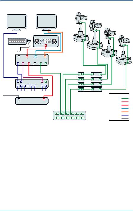
System overview
The Vinten Radamec Control (VRC) system enables an operator to remotely control a number of cameras, pedestals and pan/tilt heads. There are a number of VRC system variants, including the HDVRC, that are designed to ensure compatibility with current Fusion, Radamec and Autocam robotic products, and selected products from other manufacturers.
In this user guide, unless noted, all references to the VRC also apply to the HDVRC.
WARNING!
The VRC system should only be used by experienced television camera operators with a working knowledge of broadcast robotic equipment and systems.
A VRC system comprises a Windows XP computer with keyboard and mouse, touch screen monitor and a VRC control panel. In most applications a video switcher and tally interface are also attached to the system.
7
VRC System User Guide
VRC/HDVRC Controller |
Fusion Pedestals & Heads |
|
(or Heads only) |
Preview
Touchscreen
Monitor
Joystick Panel
|
VRC CSI Computer |
|
|
EPL |
EPL |
|
Gateways Master Nodes |
|
Out |
Video Router |
|
|
|
|
In |
- - - |
|
Tally Lines |
Inputs From Cameras |
|
|
Colour Code |
|
From |
|
|
|
Ethernet |
|
Production |
|
|
Tally Interface |
RS-232 |
|
Switcher |
|
|
|
RS-422 |
|
|
|
|
|
|
USB |
|
|
VGA |
|
Ethernet Switch |
Video |
|
|
|
|
|
Other |
Fig. 1 Typical single-controller VRC system
A VRC system can be supplied with a number of different control panel options and is configured to suit each customers specific requirements. Therefore, this guide may include references to functions that are not available on your system.
For information on system installation, configuration, technical support and troubleshooting please refer to the VRC Technical Guide (publication no. V4009-4990).
Starting the VRC software
During normal operation the controller is left powered on. However, if the server has been powered down you will need to restart the system.
1.Turn on power at the controller and the touch screen monitor.
8
Getting Started
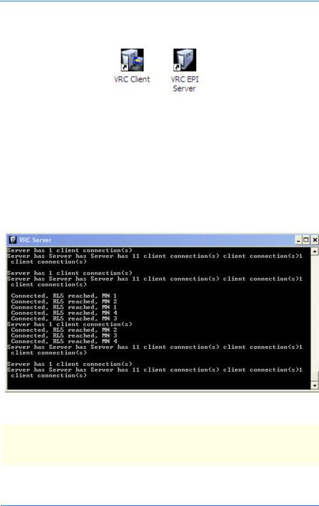
The controller will perform a standard Windows XP boot up and display the start-up screen showing the VRC shortcut icons on the desktop.
Fig. 2 VRC desktop icons
Starting the VRC EPI server
The VRC EPI server application is the communications interface to the pedestals, heads and cameras in the system and must be running at all times. You must start the EPI server before starting the VRC client application.
1.Double-click the VRC EPI Server icon.
Verify that the server commands scroll through the window continuously.
Fig. 3 VRC EPI Server window
NOTE: When the VRC system is initialised, the lights on the pedestal will flash, if the pedestals are in Auto mode (robotic control) and any heads that were in manual mode will switch to Auto mode.
The VRC EPI window can be minimised or left running in the background.
9
VRC System User Guide
Starting the VRC Client application
The client window provides all the functions to select and control the robotic heads and pedestals, allowing you to create shows using pre-programmed shots and movements.
All users must have their own user account and password to be able to log on to the VDC system. Refer to the VRC Technical Guide (publication no. V4009-4990) for instructions on adding, modifying and deleting user accounts.
NOTE: The software usage instructions in this user guide tell you to “touch” the control or required item on the touch-sensitive monitor. You can also click on that item using the mouse.
To launch the VRC client application:
1.Double-click the VRC Client icon on the desktop, to open the User Selection dialog displaying a list of all user accounts on the system.
Fig. 4 VRC EPI Server window
2.Use the Up/Down arrows to find your username in the list.
3.Touch your username in the list to select it and then touch OK. The Enter Password dialog is displayed (see page 11).
10

Getting Started
Fig. 5 VRC EPI Server window
4.Type in your password and then touch Enter to launch the VRC Client application.
For a detailed description of using the client application – See VRC Client User Interface on page 21.
Calibrating the touch screen
All VRC system monitors are touch screen enabled, allowing on-screen options to be selected by touching the relevant graphic with your finger. You can also select these options by clicking on them with the mouse. The touch screen system closely resembles the Radamec TCPi system and can control multiple camera units.
The location that you touch and the “button” on the screen are physically separated by the thickness of the touch screen glass. Therefore, depending on how you sit and your angle of view, the touch screen may need calibrating. If you find the on-screen pointer no longer matches the position of your finger on the screen you should recalibrate the touch screen.
Sitting in your normal position, locate and run the touch screen calibration utility provided by the screen manufacturer in Start > All Programs. Follow the screen instructions to calibrate the screen for your use.
Refer to the documentation provided with your screen for information on regular maintenance, cleaning and setting up your touch screen.
11

VRC System User Guide
Automation Interface
If the optional Automation Interface is installed, it operates as an additional controller. When a shot is selected at the automation system, the camera select button on the VRC controller screen will turn blue, indicating that the camera is under the control of another networked controller.
12

VRC Control Panel
The VRC system is consists of a computer with a touch screen that runs the VRC application software and a hardware control panel. These two control systems are designed to provide a logical and easy-to-use interface enabling you to control all aspects of the VRC and the attached camera systems.
The VRC control panel enables you to select and control connected camera units (incl. camera, pan/tilt head and optional pedestal) to obtain the correct views for the required shots.
Overview
The VRC control panel is designed to integrate with the Vinten Radamec Control (VRC) software, providing control of robotic heads and pedestals. Control panels can be supplied to control either 8 or 16 camera units and with either one (Pan/Tilt/Zoom) or two (Pan/Tilt/Zoom and XY/Height) joysticks:
•The right-hand joystick (Pan/Tilt/Zoom) controls the pan and tilt movements of the robotic head and the zoom functions on the camera lens.
•The optional left-hand joystick (XY/Height) controls the steering, travel and height of the robotic pedestals.
The VRC firmware allows up to 8 axes of movement to be operated at the same time.
There are also options that can control the camera Iris and Black CCU functions.
This guide details the use of all control panel variations, and therefore some functions may not be present on your control panel. If a button or control described in the text or illustrations is not present on your control panel, then your model does not support that function. It is also possible that the installation engineer may customise the functionality of the system function buttons affecting functions available and their precise location on the panel.
Whilst these control panels are designed to control Fusion and SP2000 robotic products, there is also an option to support the functionality of the RP2A pedestal.
13

14 |
|
|
|
|
|
|
|
|
|
|
|
|
|
|
|
VRC |
|
1 |
2 |
3 |
|
4 |
5 |
6 |
|
7 |
8 |
|
9 |
|
11 |
12 |
System |
|
|
|
|
10 |
13 |
|||||||||||
6 .Fig |
|
|
|
|
|
|
|
|
|
|
|
|
|
|
|
GuideUser |
Dual |
BLACK |
IRIS |
|
|
|
|
|
|
|
|
|
|
|
|
|
|
|
|
|
|
wash |
over |
joystick |
infrared |
bumper |
pan |
target |
backup |
x4 |
panel |
on air |
|
|
|
|
|
|
follow |
|
|||||||||||
Joystick |
HEIGHT |
|
|
|
wipe |
ride |
enable |
disable |
disable |
disable |
link |
|
disable |
ZOOM |
||
|
|
|
|
|
|
|
|
|
|
|
|
|
|
|||
Y |
|
|
CUT |
|
cam1 cam2 |
cam3 |
cam4 |
cam5 |
cam6 |
cam7 |
cam8 |
|
|
TILT |
||
|
|
|
|
|
|
|||||||||||
VRC |
|
|
|
FADE |
|
|
|
|
camera preview |
|
|
|
|
|
|
|
|
|
|
|
|
|
|
|
|
|
|
|
|
|
|
||
control |
X |
|
|
|
|
|
|
|
|
|
|
|
|
|
|
PAN |
|
|
FADE |
STOP |
|
cam9 |
cam10 cam11 cam12 cam13 |
cam14 cam15 cam16 |
|
|
|
||||||
|
|
TIME |
|
|
|
|
||||||||||
|
|
|
|
|
|
|
|
|
|
|
|
|
|
|
||
FOCUS |
|
|
|
|
|
|
|
|
|
|
|
|
|
|
|
|
panel |
|
|
|
|
|
|
|
|
|
|
|
|
|
|
|
|
|
|
|
|
|
|
|
|
|
|
|
|
|
|
|
|
|
21 |
20 |
19 |
18 |
17 |
16 |
|
|
|
15 |
|
|
|
|
|
14 |
|

VRC Control Panel
[1] . . . . . . . . . . . . . . . . . . . . . . . . . . . . . . . . . . . . . . . . . . . . . . . . . . . . . CCU black level (option) [2] . . . . . . . . . . . . . . . . . . . . . . . . . . . . . . . . . . . . . . . . . . . . . . . . . . . . . . . . . . . CCU iris (option) [3] . . . . . . . . . . . . . . . . . . . . . . . . . . . . . . . . . . . . . . . . . . . . . . . . . . . . . . . . Wash/Wipe (option) [4] . . . . . . . . . . . . . . . . . . . . . . . . . . . . . . . . . . . . . . . . . . . . . . . . . . . . . . . . . . . . . . . . . Override [5] . . . . . . . . . . . . . . . . . . . . . . . . . . . . . . . . . . . . . . . . . . . . . . . . . . . . . . . . . . . . Joystick enable [6] . . . . . . . . . . . . . . . . . . . . . . . . . . . . . . . . . . . . . . . . . . . . . . . . . . . . . . . . . . . . Infrared disable [7] . . . . . . . . . . . . . . . . . . . . . . . . . . . . . . . . . . . . . . . . . . . . . . . . . . . . . . . . . . . .Bumper disable [8] . . . . . . . . . . . . . . . . . . . . . . . . . . . . . . . . . . . . . . . . . . . . . . . . . . . . . . . . . . . . . . . . Pan follow [9] . . . . . . . . . . . . . . . . . . . . . . . . . . . . . . . . . . . . . . . . . . . . . . . . . . . . . . . . . . . . . Target disable [10] . . . . . . . . . . . . . . . . . . . . . . . . . . . . . . . . . . . . . . . . . . . . . . . . . . . . . . . . . . . . . . Backup link [11] . . . . . . . . . . . . . . . . . . . . . . . . . . . . . . . . . . . . . . . . . . . . . . . . . . . . . . . . . . . . . . . . . . . . . X4 [12] . . . . . . . . . . . . . . . . . . . . . . . . . . . . . . . . . . . . . . . . . . . . . . . . . . . . . . . . . . . . Panel disable [13] . . . . . . . . . . . . . . . . . . . . . . . . . . . . . . . . . . . . . . . . . . . . . . . . . . . . . .Pan/Tilt/Zoom joystick [14] . . . . . . . . . . . . . . . . . . . . . . . . . . . . . . . . . . . . . . . . . . . . . . . . . . . . . . . On air tally indicator [15] . . . . . . . . . . . . . . . . . . . . . . . . . . . . . . . . . . . . . . . . . . . . . . . . .Camera select buttons 1–16 [16] . . . . . . . . . . . . . . . . . . . . . . . . . . . . . . . . . . . . . . . . . . . . . . . . . . . . . . . . . . . . . . . . . . . . Cut [17] . . . . . . . . . . . . . . . . . . . . . . . . . . . . . . . . . . . . . . . . . . . . . . . . . . . . . . . . . . . . . . . . . . . Fade [18] . . . . . . . . . . . . . . . . . . . . . . . . . . . . . . . . . . . . . . . . . . . . . . . . . . . . . . . . . . . . . . . . . . . .Stop [19] . . . . . . . . . . . . . . . . . . . . . . . . . . . . . . . . . . . . . . . . . . . . . . . . . . . . . . . . . . . . . . . Fade time [20] . . . . . . . . . . . . . . . . . . . . . . . . . . . . . . . . . . . . . . . . . . . . . . . . . . . . . . . . . . . . . . . . . . Focus [21] . . . . . . . . . . . . . . . . . . . . . . . . . . . . . . . . . . . . . . . . . . . . . . . . . . . . . . . . X/Y/Height joystick
Switching on the panel
When power is initially connected to the control panel, all push buttons will sequentially illuminate and then extinguish after a period of approximately 3 seconds.
Configuring the operation of the control panel
The default mode of some of the control panel functions and the sense of joystick controls can be set in the system Configuration – See Configuration on page 65.
Tally Indicators
The On Air (Tally) [14] indicators show which camera’s video signal is currently live on air.
Locking the control panel
The Panel Disable [12] button locks all other controls on the panel to prevent accidental operation.
15

VRC System User Guide
Disabling the Panel Disable button
The DIP switch in the control panel can be used to disable the Panel Disable button. If the switch is set to ‘ON’ the button is disabled, if the switch is set to ‘OFF’ the button will operate normally.
Controlling a camera unit
Most of the controls (buttons, joysticks and rotary knobs) only act on the currently selected camera unit. If no unit is selected the controls will have no effect.
If the selected camera unit is not mounted on a pedestal, a number of the controls will have no effect, including: Joystick enable, XY/Height joystick, Pan Follow and Bumper Disable. In addition, Override, Target Disable, Backup Link and Infrared Disable controls are only available if the camera unit is mounted on a RP2A pedestal.
The Cut/Fade/Stop and Fade Time controls parallel controls in the VRC client application software, affecting how the software moves between stored shots.
Selecting a camera
The Camera Select buttons [15] allow selection of individual camera units (camera, pan and tilt head and pedestal – where fitted). Once selected, the depressed push button illuminates and the camera unit can be controlled by the joysticks.
If the optional video switcher and preview monitor are installed, the video from the selected camera is displayed on the video monitor enabling you to set up the shot.
NOTE: If a selected camera unit is not available (e.g. because it is in Manual mode), the camera cannot be selected and the select button will not light.
Button mapping
The default order in which cameras appear on the control panel and touch screen Camera Select buttons is determined by the system configuration files.
The Button Mapping utility (see VRC Technical Guide, publication no. V4009-4990) can be used to map any camera to any button (or multiple buttons) on the control panel and touch screen as part of a Button Map group.
You can define multiple button map groups to match your workflows. These groups are displayed in the workspace screen above the shots frames and can be selected by touching the button on the screen.
16

VRC Control Panel
Pan/Tilt/Zoom joystick
This joystick [13] controls the pan and tilt movements of the head and the lens Zoom function. By default:
•Moving the joystick left and right will pan the camera left and right.
•Moving the joystick forward and back will tilt the camera down and up, respectively.
•Rotating the joystick clockwise will zoom out the camera lens.
•Rotating the joystick counter-clockwise will zoom in.
If required, the direction of camera and zoom movement relative to joystick movement can be customised in the Configuration Screen - See Configuration on page 65.
Focus control
Rotating the Focus knob [20] adjusts the camera lens focus.
Black level and Iris CCU controls
If the optional CCU interface is installed, the CCU Black level [1] and Iris [2] functions can be controlled by rotary knobs on the left hand side of the control panel in addition to the VRC user interface – See CCU Interfaces on page 53.
Wash wipe
The Wash Wipe button [3] activates the wash wipe on the selected externally mounted environmental camera unit.
X4
During normal operation, the X4 button [11] is off (zoom proportional mode is on) so that the speed of the pan and tilt movements are proportional to the zoom angle of the camera lens. Pan and tilt move slowly when you are zoomed in and quickly when you are zoomed out.
When X4 is on (zoom proportional mode is off), the pan and tilt movements are more sensitive when zoomed in.
NOTE: For the FHR-120 head, X4 is always off (zoom proportional mode is ON).
17

VRC System User Guide
Remote pedestal operation
The following functions are used to remotely operate a robotic pedestal. There are additional functions on the control panel that are used only when operating an RP2A pedestal – See RP2A control functions on page 20.
Pedestal orientation
The sides of the pedestal are referred to as North, South, East and West.
North side
East side
West side
South side
Fig. 7 Fusion FP-145/FP-188 – Pedestal orientation
Joystick enable
The Joystick Enable button [5] must be on and illuminated before you can move the pedestal around the studio floor (in X and Y axes) using the XY/Height joystick.
When the Joystick Enable button is off, the XY/Height joystick only allows robotic height movement. This prevents accidental pedestal travel while rotating the joystick to adjust camera height.
18

VRC Control Panel
XY/Height joystick
The XY/Height joystick [21] is on the left-hand side of the control panel and is used to operate a pedestal. By default:
•Moving the joystick left and right will cause the pedestal to travel West and East, respectively, relative to the target.
•Moving the joystick forward and back will cause the pedestal to move North and South, respectively. North is the direction away from the side of the pedestal that has the cable connection panel – See Pedestal orientation on page 18.
•Rotating the joystick clockwise will lower the camera and rotating it counterclockwise will raise the camera.
If required, the direction of camera movement relative to joystick movement can be customised in the Configuration Screen – See Configuration on page 65.
NOTE: Before the pedestal can travel across the studio floor, the Joystick Enable button must be depressed and illuminated.
Pan follow
When Pan Follow [8] is off, pushing the XY/Height joystick forwards and backwards on the Y axis causes the pedestal to travel North and South as defined by the target placement. North is the direction away from the side of the pedestal with the cable connections – See Pedestal orientation on page 95.
When Pan Follow is on, pushing the XY/Height joystick forwards and backwards on the Y axis causes the pedestal to travel forwards and backwards in the direction that the camera is pointing.
Bumper disable
The Bumper Disable button [7] turns off the pedestal bumper protection which arrests the SP-2000 and RP2A pedestal travel on contact with an obstacle.
Warning!
Risk of personal injury or damage to equipment when the
Bumper Disable button is depressed.
19
VRC System User Guide
RP2A control functions
The following functions are only applicable when operating the RP2A pedestal. These functions are additional to the other pedestal functions listed above.
Override
The Override button [4] allows the selected RP2A pedestal to continue moving at quarter speed after the detection of an infrared proximity warning or collision with an obstacle. Override will have no effect on proximity detection if Infrared Disable is ON. Override will have no effect on collision with an obstacle if Bumper Disable is ON.
Target disable
The Target Disable button [9] prevents the RP2A pedestal from using the optical studio targets. The selected pedestal will continue to only use the dead reckoning positional system.
Backup link
The Backup Link button [10] gives priority control to the control panel in the unlikely event of the VRC system failing. This allows the robotic camera units to remain in operation.
Infrared disable
Where fitted, the Infrared Disable button [6] turns off the selected Radamec RP2A pedestal infrared proximity protection (which arrests pedestal travel before contact with an obstacle).
Warning!
Risk of personal injury or damage to equipment when the
Infrared Disable button is depressed.
NOTE: If ALWAYS DISBLE IR is enabled in the Configuration – See Panel options on page 70, the control panel will have the INFRARED DISABLE function activated by default.
20
VRC Client User Interface
The VRC system is consists of a computer with a touch screen that runs the VRC application software and a hardware control panel. These two control systems are designed to provide a logical and easy-to-use interface enabling you to select and control connected camera systems. The VRC client application enables you to set up, store, manage and select the shots for shows.
Client workspace
The VRC Client application is a GUI-driven, MS Windows-based program.

 Fusion-TCPI (V0.0.29.0) User: XXX Show: Test
Primary Panel Groups |
|
|
|
|
|
|
|
|
|
|
|
|
|
|
|
|
|
|
|
|
|
|
|
|
|
|
|||
|
|
|
|
|
|
|
|
|
|
|
|
|
|
|
|
|
|
|
|
||||||||||
|
|
|
Show A |
|
|
|
Test Script |
HD Trial |
|
Studio 1 |
|
Evening |
MIDDAY |
TEST D |
|
Test 4 |
|||||||||||||
|
|
|
|
|
|
|
|
|
|
|
|
|
|
|
|
|
|
|
|
|
|
|
|
|
|
|
|
|
|
|
|
|
|
|
|
|
|
|
|
|
|
|
|
|
|
|
|
Viewing shots for FP-188 |
|
|
|
|
|
|
|||||
|
|
|
A |
|
|
|
|
|
|
B |
|
|
|
|
|
|
C |
|
D |
|
|
E |
|
F |
|||||
|
|
|
|
|
|
|
|
|
|
|
|
|
|
|
|
|
|
|
|
|
|
|
|
|
|
|
|
||
|
|
|
|
|
|
|
|
|
|
|
|
|
|
|
|
FP-188 |
|
|
|
|
|
|
|
|
|
|
|
||
1 |
|
|
|
|
|
|
|
|
|
|
|
|
|
|
|
|
|
|
|
|
|
|
|
|
|
|
|
|
|
2 |
|
|
|
|
|
|
|
|
|
|
|
|
|
|
|
|
|
|
|
|
|
|
|
|
|
|
|
|
|
|
|
|
|
|
|
|
|
|
|
|
|
|
|
|
|
|
|
|
|
|
|
|
|
|
|
|
|
|
|
|
|
|
|
|
|
|
|
|
|
|
|
|
|
|
|
|
|
|
|
|
|
|
|
|
|
|
|
|
|
|
|
|
|
|
|
|
|
|
|
|
|
|
|
|
|
|
|
|
|
|
|
|
|
|
|
|
|
|
|
3 |
|
|
|
|
|
|
|
|
|
|
|
|
|
|
|
|
|
|
|
|
|
|
|
|
|
|
|
|
|
|
|
|
|
|
|
|
|
|
|
|
|
|
|
|
|
|
|
|
|
|
|
|
|
|
|
|
|
|
|
|
|
|
|
|
|
|
|
|
|
|
|
|
|
|
|
|
|
|
|
|
|
|
|
|
|
|
|
|
|
4 |
|
|
|
|
|
|
|
|
|
|
|
|
|
|
|
|
|
|
|
|
|
|
|
|
|
|
|
|
|
|
|
|
|
|
|
|
|
|
|
|
|
|
|
|
|
|
|
|
|
|
|
|
|
|
|
|
|
|
|
|
|
|
|
|
|
|
|
|
|
|
|
|
|
|
|
|
|
|
|
|
|
|
|
|
|
|
|
|
|
|
|
|
|
|
|
|
|
|
|
|
|
|
|
|
|
|
|
|
|
|
|
|
|
|
|
|
|
|
|
|
|
|
|
|
|
|
|
|
|
|
|
|
|
|
|
|
|
|
|
|
|
|
|
|
|
|
|
|
|
Camera Selection and Status |
|
|
|
|
|
|
|
|
|
|
|
|
|
|
|
|
|
|
|
|
|
FP-188 |
|||||||
|
|
|
|
|
|
|
|
|
|
|
|
|
|
|
|
|
|
|
|
|
|
|
|
|
|
|
|
|
FP-188 |
|
|
|
|
|
|
|
|
|
|
|
|
|
|
|
|
|
|
|
|
|
|
|
|
|
|
|
|
|
|
|
|
|
100 Head |
|
Fusion-2 |
FP-188 |
|
|
Fusion-4 |
|
|
Fusion-5 |
|
Fusion-6 |
Fusion-7 |
Fusion-8 |
|
|
|||||||||||
Camera 9 |
FP-145 |
FP-145-2 |
FHR120 |
FHR120-2 |
FP-188/3 |
FP-188/2 |
Alternate |
Menu |
Edit |
Stop |
Cut |
Fade |
Store |
Focus |
Sequence |
Virtual |
Page Up |
Page |
Opts |
|
Stick |
Down |
|||||||||||
|
|
|
|
|
|
|
|
|
|
Fig. 8 The VRC Client window
21

VRC System User Guide
The VRC user interface window works in the same way as other application windows, allowing you to reposition the window on your computer desktop by dragging it with the mouse, minimise the window (so that it appears only as an icon on your task bar), maximise the window (so that it appears full screen) and close the application using the Close button.
The window comprises:
•Title bar
•Primary Panel Groups bar
•Stored shot grid, comprising a grid of cells displaying thumbnails of stored shots
•Camera selection and status bar showing up to 16 cameras
•Toolbar containing function and menu buttons.
In addition, a Preview Panel Groups bar can be displayed directly below the Primary Panel Groups bar.
The Primary and Preview Panel Groups bars are only displayed if they are enabled in the configuration. The bars can be positioned either above or below the stored shot grid – see Group display preferences on page 75.
Title bar
The title bar displays the current user logon name (e.g. “XXX” in Fig. 8) and the name of the current show (e.g. “Test” in Fig. 8), if one has been loaded.
Primary Panel Groups bar
This optional bar shows any configured Camera Map groups that are defined. If more than eight groups are defined, arrows at the ends of the bar become active, enabling you to move back and fore along the groups.
Primary Panel Groups |
|
|
|
|
|
|
|
Show A |
Test Script |
HD Trial |
Studio 1 |
Evening |
MIDDAY |
TEST D |
Test 4 |
Fig. 9 Primary Panel Groups bar
Selecting one of the groups will map the cameras to the selection buttons defined in that group.
22

VRC Client User Interface
Preview Panel Groups bar
This optional bar displays the same groups as the Primary Panel Groups bar and enables the operator to select a second camera mapping group (possibly for a different studio) to setup the initial shots for another show while the current show is still running.
The Preview Panel Groups function would normally only be used if there were fewer than eight cameras in each show. The camera mapping would be setup with:
•The cameras for the current show (selected Primary Panel Group) on the top row of the Camera Selection and Status bar.
•The cameras for the next show (selected Preview Panel Group) on the bottom row of the Camera Selection and Status bar.
This would enable you to control the cameras in both the Primary and Preview groups simultaneously.
NOTE: The Display Full Panel configuration option needs to be enabled before using the Preview Panel Groups. If only eight cameras are being shown in the Camera Selection and Status bar, these will be the first 8 cameras for the Primary Panel Group and you will be unable to see the camera buttons for the preview group.
Once the production moves to this other studio, the operator simply selects the group that was selected in the preview mapping group in the Primary Panel Groups bar and runs that show.
This enables a single operator to control multiple studios from a single control panel.
Stored shot editing grid
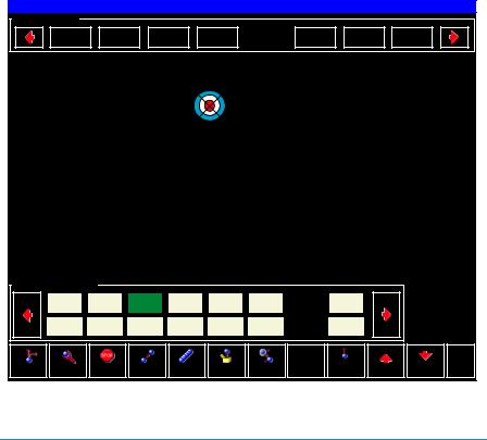
This grid of cells is used to display the shots that have been created and stored for each camera in the current show, or the shots stored for the currently selected camera depending on the setting of the Per Camera configuration option. The grid size (number of shots that are visible on a single page can be selected using the Grid Size option on the Configuration Screen – see Grid display options on page 66.
Every time a shot is stored, a thumbnail image is captured from the camera and saved into the selected cell. These thumbnails allow you to quickly identify the shots without requiring long descriptive names. Depending on the number of shots stored in the current show and the grid size selected, the shots may span several pages.
After shots are stored they can be moved, edited or deleted using the options on the Edit menu – see Edit menu on page 31.
23

VRC System User Guide
Shot thumbnails
When a shot is stored a thumbnail image is captured and displayed in the selected cell. This thumbnail will be surrounded by a frame and has the camera name superimposed across the top of the thumbnail.
Camera Name
Shot Name
Shot Time
Fig. 10 Shot thumbnail annotations
Optionally, if selected in the Shot Options – see Shot options on page 72, the name of the shot and the shot time will also be superimposed across the thumbnail (see Fig. 10).
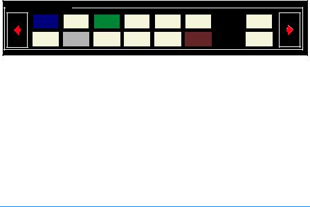
Shot status colour codes
The frames around the shots and the background of the text bars stored in the editing pane are colour coded to indicate the shot status.
Fig. 11 Shot status colour codes
24
|
|
VRC Client User Interface |
|
|
|
|
Frame Colour |
Description |
|
|
|
|
Red |
Indicates that the camera is moving (via Cut or Fade) to |
|
|
the shot. See shot A1, above. |
|
|
|
|
Yellow banner across |
Indicates that this was the last shot selected. See shot |
|
frame corner |
A1, above. |
|
|
|
|
Green |
Indicates that this shot is cued and the camera will |
|
|
move to this shot when you select Cut or Fade. See |
|
|
shot F7, above. |
|
|
|
|
Dark blue |
Indicates that the camera is exactly on shot as stored in |
|
|
the show file. See shot E5, above. |
|
|
|
|
Light blue |
Indicates that the camera has been trimmed off the |
|
|
shot stored in the show file. See shot C4, above. |
|
|
|
|
Grey |
Indicates shots that are available for selection. |
|
|
|
Camera selection and status bar
The robotic pedestals and heads can be selected from the workspace or the control panel. The Camera selection and status bar is located immediately below the editing pane and displays the available cameras.
Camera Selection and Status |
|
|
|
|
|
|
|
100 Head |
Fusion-2 |
FP-188 |
Fusion-4 |
Fusion-5 |
Fusion-6 |
Fusion-7 |
Fusion-8 |
Camera 9 |
FP-145 |
FP-145-2 |
FHR120 |
FHR120-2 |
FP-188/3 |
FP-188/2 |
Alternate |
Fig. 12 Camera selection and status bar
The number of camera units displayed in this bar depends on a number of configuration functions:
•If button mapping is not enabled, this bar can be used to display either 8 or 16 camera units, depending on the setting of the Display Full Panel configuration option – see Panel options on page 70. If more than the 8 or 16 camera units are connected on the system, the arrow buttons can be used to page to the other cameras.
•If Primary Panel Groups are enabled, this bar will display up to 16 cameras units.
25

VRC System User Guide
•If Preview Panel Groups are also enabled, this bar will display the first 8 camera units for the primary group across the top and the first 8 camera units for the preview group across the bottom of the bar.
NOTE: The camera buttons on the control panel are always the same as the buttons currently displayed on the touch screen.
Camera unit status colour code
The colour of the camera button indicates the current status of the camera.
Button |
Description |
|
Colour |
||
|
||
|
|
|
Green |
Camera currently selected and controlled by the control panel. |
|
|
|
|
White |
Camera available for immediate selection and control. |
|
|
|
|
Black |
Camera is offline and unavailable. see Troubleshooting on |
|
|
page 85 for guidance. |
|
|
|
|
Blue |
Camera is currently under the control of another networked |
|
|
control panel. Depending on your user account privileges, you |
|
|
may be able to take control of that camera unit. |
|
|
|
|
Brown |
Pedestal is in Local/Manual mode. Switch the pedestal to Auto |
|
|
mode and then bring it online by selecting Opts > Enable and |
|
|
the button will turn white when the camera is enabled. see Opts |
|
|
menu on page 35 for more information. |
|
|
|
|
Grey |
Head is in Local/Manual mode. Bring the head online by |
|
|
selecting Opts > Enable. See Opts menu on page 35 for more |
|
|
information. |
|
|
|
Selecting Camera Units
Only camera buttons that are white or blue can be selected from the touch screen (a green button indicates that camera is currently selected).
Depending on your user account privileges, if a camera unit is under control of another networked control panel (button coloured Blue) you may be able to take control of that camera using the take rudely function – see Camera control on page 73.
If you have permission to ‘take rudely’, selecting the camera displays a confirmation dialog (‘Device is being used by another operator, continue?’). Selecting ‘Yes’ will transfer control of the camera to your control panel and the button turns Green.
26

VRC Client User Interface
Once selected, any camera can be controlled from the joystick control panel, or using the virtual joystick and controls on the touch screen.
When a camera is selected, you can elect to only display the shots stored for that camera in the Stored Shot Pane, if the Per Camera configuration option is selected – see Grid display options on page 66.
A text field indicating the selected camera is displayed above the grid of shots.
Button mapping
The default order in which cameras appear on the touch screen Camera Selection and Status buttons and the control panel camera select buttons is determined by the system configuration files. The Button Mapping utility program (refer to the VRC Technical Guide, publication no. V4009-4990) can be used to map any camera to any button (or to multiple buttons) on the control panel and touch screen as part of a
Button Map group.
You can define multiple button map groups of cameras to match your workflow. Button map groups are displayed above the grid on the touch screen, if they are enabled in the Configuration screen – see Group display preferences on page 75.
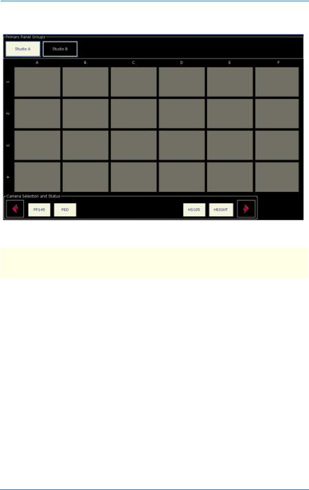
Typical workspaces for two button map groups called Studio A and Studio B were configured using the assignments listed below:
|
Studio A |
|
|
Studio B |
||
|
|
|
|
|
|
|
Button # |
|
Device |
|
Button # |
|
Device |
|
|
|
|
|
|
|
1 |
|
FP145 (pedestal) |
1 |
|
|
PED (SP-2000) |
|
|
|
|
|
|
|
2 |
|
PED (SP-2000) |
2 |
|
|
HEIGHT (FBH175) |
|
|
|
|
|
|
|
3 |
|
Not assigned |
3 |
|
|
2010 (HS-2010) |
|
|
|
|
|
|
|
4 |
|
Not assigned |
4 |
|
|
Not assigned |
|
|
|
|
|
|
|
5 |
|
Not assigned |
5 |
|
|
Not assigned |
|
|
|
|
|
|
|
6 |
|
Not assigned |
6 |
|
|
Not assigned |
|
|
|
|
|
|
|
7 |
|
HS105 |
7 |
|
|
Not assigned |
|
|
|
|
|
|
|
8 |
|
HEIGHT (FBH175) |
8 |
|
|
Not assigned |
|
|
|
|
|
|
|
27
VRC System User Guide
The workspace with Studio A selected is shown below:
Fig. 13 The VRC workspace
NOTE: The mapping of the camera select buttons on the control panel follows the touch screen mapping.
Function buttons and menus
The toolbar containing the function and menu buttons is displayed at the bottom of the workspace. The buttons and menus enable you to:
•Create and manage shows
•Create and edit shots
•Target and stop pedestals
•Configure the VRC system
28
VRC Client User Interface
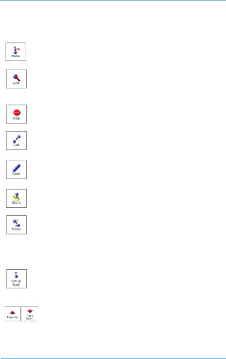
The function and menu buttons are:
Button |
Function |
Description |
|
|
|
|
Menu |
Displays the Menu dialog enabling you to: manage |
|
|
shows, access the configuration utility and clear all |
|
|
the shots from the current show. |
|
|
|
|
Edit |
Displays the Edit menu enabling you to: rename a |
|
|
shot, delete a shot, edit the shot time, replace a |
|
|
stored shot with a new one and move shots to |
|
|
different positions in the grid. |
|
|
|
|
Stop |
Stops all pedestal and head movement during a cut |
|
|
or fade operation. |
|
|
|
|
Cut |
Cuts from the current shot to the selected shot. |
|
|
This function can be latched to immediately Cut to a |
|
|
shot when it is selected. |
|
|
|
|
Fade |
Fades from the current shot to the selected shot. |
|
|
This function can be latched to immediately Fade to a |
|
|
shot when it is selected. |
|
|
|
|
Store |
Stores the shot set-up on the currently selected |
|
|
camera unit into the selected cell in the grid. |
|
|
|
|
Focus |
Zooms the lens of the current on Shot camera unit |
|
|
(thumbnail coloured dark blue) all the way in tight and |
|
|
displays the Focus menu. |
|
|
|
|
Sequence |
Not available in this version of the VRC control |
|
|
software. |
|
|
|
|
Virtual |
Displays the Virtual Joystick window, providing a |
|
Stick |
method of manually controlling pedestals and heads |
|
|
from the touch screen when a control panel is not |
|
|
available. |
|
|
|
|
Page Up/ |
Enables you to scroll up and down through the pages |
|
Page |
of stored shots. |
|
Down |
|
|
|
|
29
Loading...