


End-User Configuration Guide
ICE Tool
Intelligent Control Engineering
Version 2.3.2.281
Installation
EN
Part No. V4096-8001
www.vintenradamec.com

Copyright © 2012
All rights reserved.
Original Instructions: English
All rights reserved throughout the world. No part of this document may be stored in a retrieval system,
transmitted, copied or reproduced in any way, including, but not limited to, photocopy, photograph,
magnetic or other record without the prior agreement and permission in writing of the Vitec Group plc.
Disclaimer
The information contained in this manual is believed to be correct at the time of printing. Vitec Videocom
Ltd reserves the right to make changes to the information or specifications without obligation to notify any
person of such revision or changes. Changes will be incorporated in new versions of the publication.
We are making every effort to ensure that our manuals are updated on a regular basis to reflect changes
to product specifications and features. Should this manual not contain information on the core functionality
of your product, please let us know. You may be able to access the latest revision of this manual from our
website.
Vitec Videocom Ltd reserves the right to make changes to product design and functionality without
notification.
Trademarks
All product trademarks and registered trademarks are the property of The Vitec Group Plc.
All other trademarks and registered trademarks are the property of their respective companies.
Published by:
Vitec Videocom Ltd
Supports Technical Publications Department
Western Way, Bury St Edmunds
Suffolk IP33 3TB
United Kingdom
Email: technical.publications@vitecgroup.com

Safety and About this Manual . . . . . . . . . . . . . . . . . . . . . . . . . . . . . . . . . . . . . . . . . . . . . . . . . . . . . . . . 2
Installing ICE Tool . . . . . . . . . . . . . . . . . . . . . . . . . . . . . . . . . . . . . . . . . . . . . . . . . . . . . . . . . . . . . . . . . 3
PC Ethernet Connections . . . . . . . . . . . . . . . . . . . . . . . . . . . . . . . . . . . . . . . . . . . . . . . . . . . . . . . . . . . 5
Ethernet Configuration . . . . . . . . . . . . . . . . . . . . . . . . . . . . . . . . . . . . . . . . . . . . . . . . . . . . . . . . . . . . . 6
Using ICE Tool . . . . . . . . . . . . . . . . . . . . . . . . . . . . . . . . . . . . . . . . . . . . . . . . . . . . . . . . . . . . . . . . . . . . 8
Starting ICE Tool . . . . . . . . . . . . . . . . . . . . . . . . . . . . . . . . . . . . . . . . . . . . . . . . . . . . . . . . . . . . . . . . 8
Adding Devices . . . . . . . . . . . . . . . . . . . . . . . . . . . . . . . . . . . . . . . . . . . . . . . . . . . . . . . . . . . . . . . . . 8
General Device Configuration . . . . . . . . . . . . . . . . . . . . . . . . . . . . . . . . . . . . . . . . . . . . . . . . . . . . . . . . 9
Opening Devices and Components . . . . . . . . . . . . . . . . . . . . . . . . . . . . . . . . . . . . . . . . . . . . . . . . . . 9
Ethernet Configuration . . . . . . . . . . . . . . . . . . . . . . . . . . . . . . . . . . . . . . . . . . . . . . . . . . . . . . . . . . . . 9
Renaming Devices . . . . . . . . . . . . . . . . . . . . . . . . . . . . . . . . . . . . . . . . . . . . . . . . . . . . . . . . . . . . . . .11
Rebooting Devices . . . . . . . . . . . . . . . . . . . . . . . . . . . . . . . . . . . . . . . . . . . . . . . . . . . . . . . . . . . . . . .11
About ICE Tool . . . . . . . . . . . . . . . . . . . . . . . . . . . . . . . . . . . . . . . . . . . . . . . . . . . . . . . . . . . . . . . . . .11
Head Configuration . . . . . . . . . . . . . . . . . . . . . . . . . . . . . . . . . . . . . . . . . . . . . . . . . . . . . . . . . . . . . . . 12
Identifying Individual Heads . . . . . . . . . . . . . . . . . . . . . . . . . . . . . . . . . . . . . . . . . . . . . . . . . . . . . . . 12
Head Axis Configuration . . . . . . . . . . . . . . . . . . . . . . . . . . . . . . . . . . . . . . . . . . . . . . . . . . . . . . . . . 12
GP I/O Configuration . . . . . . . . . . . . . . . . . . . . . . . . . . . . . . . . . . . . . . . . . . . . . . . . . . . . . . . . . . . . 16
VR Configuration . . . . . . . . . . . . . . . . . . . . . . . . . . . . . . . . . . . . . . . . . . . . . . . . . . . . . . . . . . . . . . . 17
Copying Configurations . . . . . . . . . . . . . . . . . . . . . . . . . . . . . . . . . . . . . . . . . . . . . . . . . . . . . . . . . . 18
Exporting Configurations . . . . . . . . . . . . . . . . . . . . . . . . . . . . . . . . . . . . . . . . . . . . . . . . . . . . . . . . . 19
Contents
1
Safety and About this Manual
Bottom half of the window
Top right hand quarter
of the window
Important information on the safe installation and operation of this
product. Read this information before operating the product. For
your personal safety, read these instructions. Do not operate the
product if you do not understand how to use it safely. Save these
instructions for future reference.
Warning Symbols Used in these Instructions
Safety cautions are included in these instructions. These safety
instructions must be followed to avoid possible personal injury and
avoid possible damage to the product.
WARNING!
Where there is a risk of personal injury or injury to others,
comments appear supported by the warning triangle symbol.
Where there is a risk of damage to the product, associated
equipment, process or surroundings, comments appear
supported by the word ‘Caution’.
Intended Use
The ICE Tool software is designed to be installed on a desktop or laptop
computer and then connect to ICE compatible robotic support
equipment via an Ethernet interface. The primary function of the ICE
Tool software is to assist in the configuration of an ICE robotic system.
Safety when Working with Robotic Equipment
In normal operation remote-controlled equipment can move suddenly
and without warning. Since audible warnings are not suitable for use
within the studio environment, it is recommended that only trained
personnel be allowed to work in the active areas where remotecontrolled heads and pedestals are located. The safe operating zone is
a minimum of 1 m (3 ft). Do not operate robotic equipment if you cannot
see it.
2
About this Manual
The ICE Tool has been designed as a configuration software
application compatible with the range of Vinten Radamec ICE robotic
devices. The ICE Tool is available for installation from the USB stick
supplied with any ICE product.
This manual covers the installation of the ICE Tool onto a desktop,
laptop or controller PC, how to operate it and the configuration
functions available to the user.
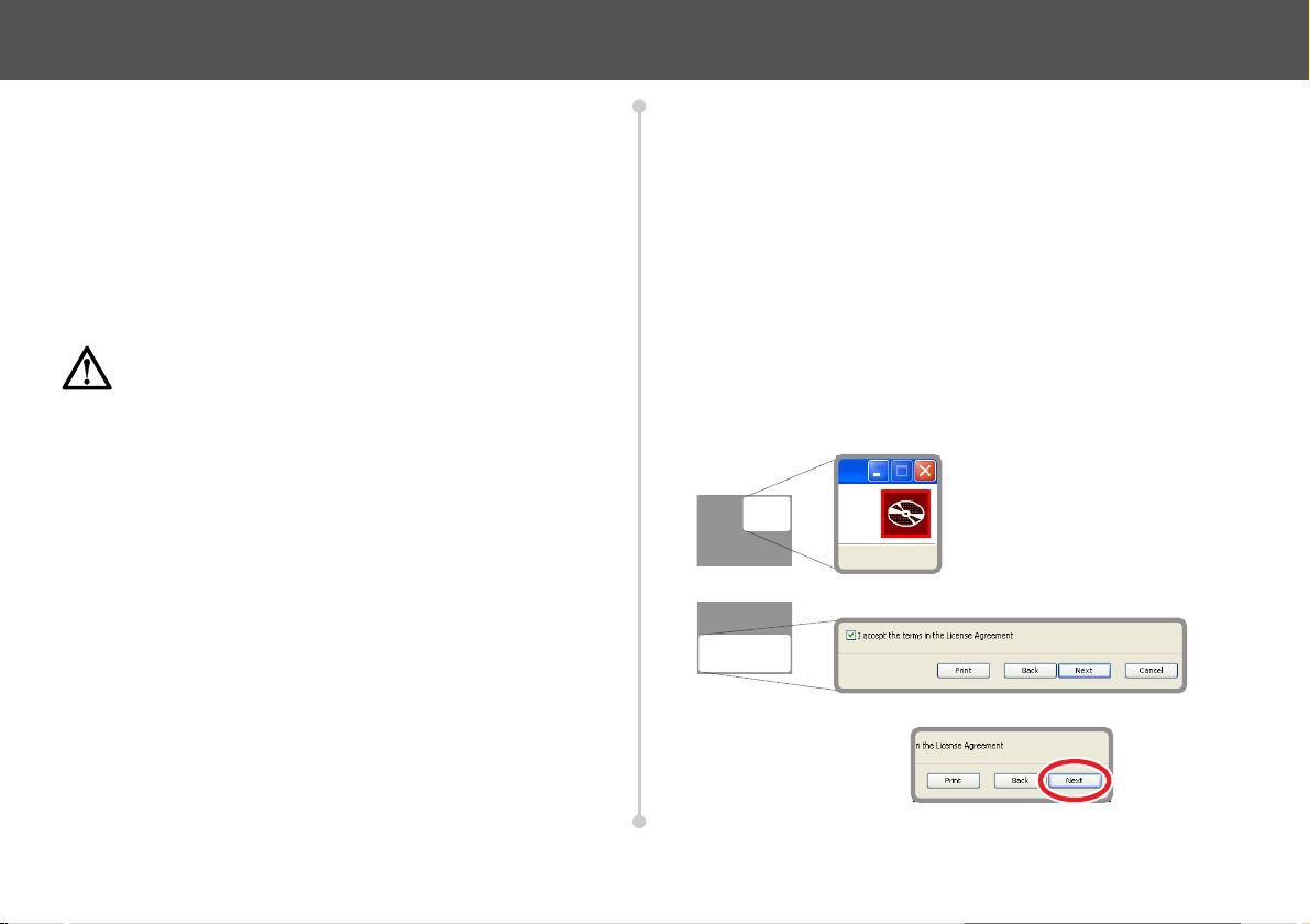
Using this Manual
This manual uses zoomed screenshots to display the relevant area of
the screen or window. The user is guided to the relevant area by a
series of navigation icons which indicate the portion of the screen being
zoomed. Two examples are shown below:
A specific feature is further
highlighted using a red
outline ring.
Installing ICE Tool
Note
ICE Tool can be installed onto a computer running Windows® XP or
Windows® 7.
If an older version of ICE Tool is present on the PC, it must
be uninstalled using Add/Remove Programs in the control
panel.
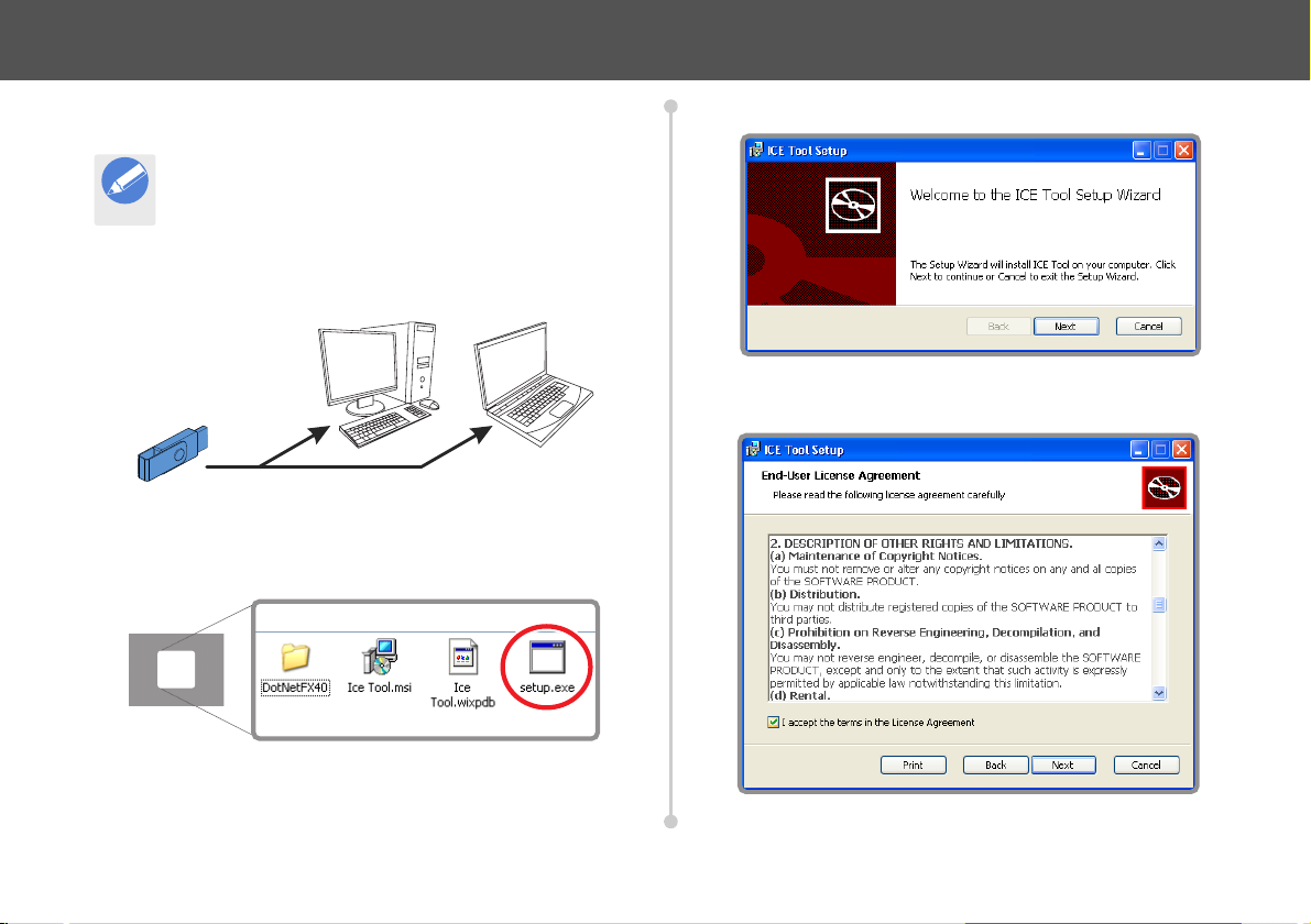
1. Insert the Vinten Radamec USB stick drive into a spare USB port
on the desktop or laptop PC.
2. Open Windows Explorer and view the contents of the USB stick
drive. Locate and open the ICE Tool folder. Double-click on the file
Setup.exe to start the installation.
3. The ICE Tool Setup window opens. Click Next to continue.
4. Select the check box to agree to accept the terms of the license
agreement. Click Next.
3
Installing ICE Tool
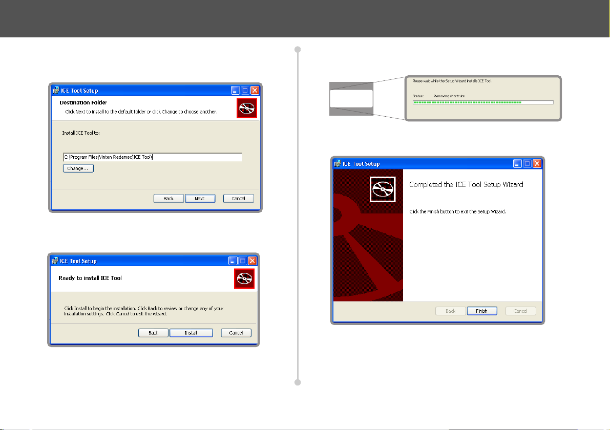
5. Select a location for ICE Tool to install to (the default location of
Program Files\Vinten Radamec\ICE Tool\ is recommended).
Click Next.
6. Click Install to proceed with the installation. Click Back to review
or change any of the installation settings.
7. Installation is automatically performed by the ICE Tool Setup
Wizard and displayed with a progress indicator.
8. When installation is complete, click Finish to exit the ICE Tool
Setup window.
4
PC Ethernet Connections
OR
Note
OR
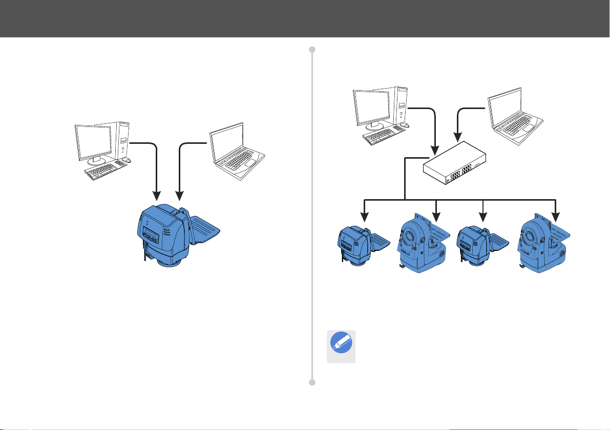
The computer installed with ICE Tool is connected to ICE robotic
devices using an Ethernet connection. This can be in two different
configurations:
Directly to one device - Direct Ethernet connection between
1
the PC and one ICE robotic device.
.
This is useful to configure a new device such as a robotic head in
isolation from a control system.
Across a robotic system to many devices - Ethernet
2
connection between the PC and a control system via a router
or network.
This gives access to all of the ICE devices within a system, but still
gives the flexibility to configure individual devices. Each ICE device in
a system is assigned a unique IP address.
ICE Tool can be installed onto a VRC or LCS controller
computer and used to connect to any ICE device in the
system.
5
Ethernet Configuration
Note
Note
The Ethernet settings on the computer must be configured to
successfully connect to an ICE device.
If ICE Tool has been installed on a VRC or LCS controller
computer, the Ethernet settings do not require further
configuration.
In a standard robotic system setup, the IP addresses assigned to
devices are in the range 198.9.200.X. The computer IP address must
be changed to this range for successful connection.
In a non-standard installation where a different range of IP addresses
has been used, the computer IP address must be changed to match
this configuration.
If the ICE device is using DHCP it is not necessary to
change the computer address to connect successfully.
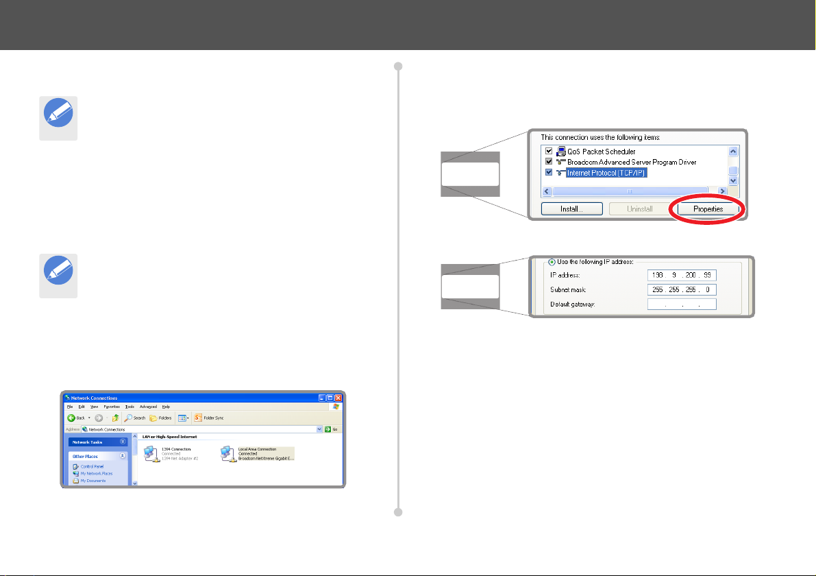
Changing the IP address Using Windows XP
1. From the Windows Start menu navigate to Control Panel >
Network Connections to open the Network Connections
window.
2. Right-click on the Local Area Connection icon and select
Properties from the menu.
3. Scroll down and select Internet Protocol (TCP/IP) and click the
Properties button.
4. The Internet Protocol (TCP/IP) Properties window opens.
a) Make a note of any current configuration settings in this
window so that they can be restored when required.
b) Click to select the Use the following IP address option.
c) Enter 198.9.200.99 (or an address appropriate for the device
or system) into the IP address field.
d) Press the Tab key to automatically populate the Subnet mask
field.
5. Click Ok to save the changes and exit the window.
6. Click Close to exit the Local Area Connection Properties
window.
6
Ethernet Configuration
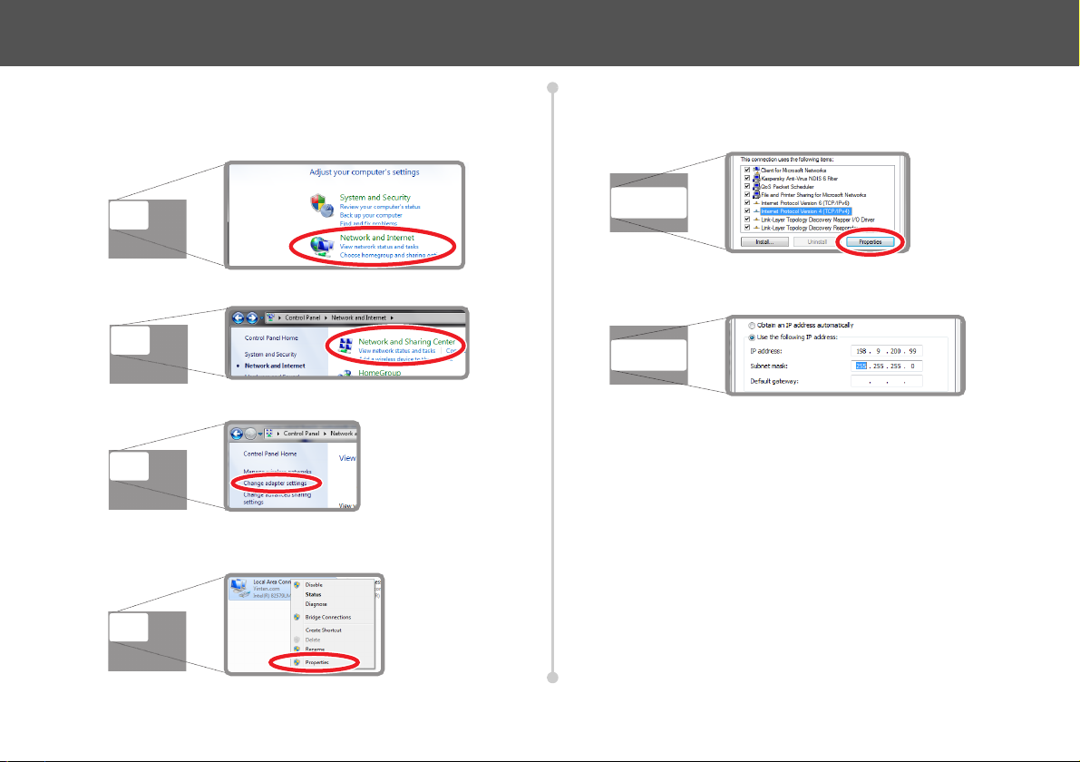
Changing the IP address Using Windows 7
1. From the Windows Start menu click to select Control Panel.
2. Click to select Network and Internet.
3. Click to select Network and Sharing Center.
4. Click on Change adaptor settings.
5. Right-click on the active local area connection and select
Properties from the menu.
6. The Local Area Connection Properties window opens. Click to
select Internet Protocol Version 4 (TCP/IPv4).
7. Click the Properties button.
8. The Internet Protocol Version 4 (TCP/IPv4) Properties window
opens.
a) Make a note of any current configuration settings displayed,
so that they can be restored when required.
b) Click to select the Use the following IP address option.
c) Enter 198.9.200.99 (or an address appropriate for the device
or system) into the IP address field.
d) Press the Tab key to automatically populate the Subnet mask
field.
9. Click Ok to save the changes and exit the window.
10. Click Ok again to exit the Local Area Connection Properties
window.
7

Using ICE Tool
Note
Starting ICE Tool
When ICE Tool has been successfully installed and an Ethernet
connection has been established:
1. From the Windows Start menu navigate to All Programs >
Vinten Radamec > Ice Tool or double-click on the ICE Tool icon
on the desktop to launch the software application.
2. The ICE Tool Login
window opens. Ensure
the default Customer
Mode is selected from
the drop-down menu
and click Continue.
Adding Devices
When ICE Tool has successfully loaded following login, the main ICE
Too l window opens. The left hand field displays a tree structure for
navigating to available ICE devices.
1. Expand the Available Hosts tree structure. Expand the product
folder(s) containing the ICE devices.
2. Right-click on the host ID of a device and select Add Host(s). This
adds the device onto the System tree for connection with ICE
Tool.
Robotic devices can also be added by selecting System >
Add Host from the top menu bar. Select the required
device(s) and click Ok. If required, all available devices can
be added to the System tree for connection with ICE Tool.
The ICE device(s) added can now be configured using ICE Tool.
8

General Device Configuration
Note
Removing Devices
If an ICE device is no longer required to be connected to ICE Tool, or it
has been added in error:
1. Right-click on the host ID of the ICE device, then select Delete.
2. When the confirmation window appears, click Yes to delete the
ICE device from the system.
The delete function is also available on the product folder to
remove all ICE devices of the same type from the System
tree simultaneously.
Opening Devices and Components
To open an ICE device for configuration:
1. Expand the System tree structure and then the required product
folder (example shown is FHR35)
2. Expand the host ID structure of the required ICE device (example
shown is 620-5B4). The individual components of the device are
displayed.
3. The active components of the ICE device are represented by
green icons . Right-click on the required component and select
Open to enter the specific component configuration window.
9

General Device Configuration
Note
Note
Ethernet Configuration
The Ethernet settings of an ICE device are accessed and configured
using ICE Tool.
1. Open the required ICE device for configuration.
2. Right-click on the Hcm component of the device and select Open.
3. The Hcm window opens.The Network Configuration field
displays the current Ethernet settings.
In the example shown Use DHCP is selected. This allows
the device to assign its own IP address on a DHCP network.
4. To change the Ethernet configuration to a specific IP address:
a) If enabled, deselect Use DHCP in the Static Configuration
area.
b) Enter the required IP address and subnet mask in the
appropriate fields (example shown is for a standard VRC
control system setup).
c) Click Apply to save the new configuration.
Use the Default button to return the Ethernet configuration
to the factory settings.
10

General Device Configuration
Note
Renaming Devices
Every ICE device has a unique host ID number. However, ICE Tool can
be used to assign a user friendly name to a device to make
identification easier in a multi-device system.
1. In the Hcm configuration window click Set Name.
2. Enter a new name in the field when prompted (example shown is
Head 1).
3. Click Ok. The new host name will take effect and is displayed at
the top of the host ID structure.
Rebooting Devices
Single or multiple devices can be rebooted using ICE Tool. This
function could be used after software upgrades, or if a device or system
has become unresponsive.
1. Select the required device(s) for reboot as shown below:
Right-Click on: Select: Action
The host ID of a
single device.
The product
folder.
The System
icon.
Reboot. Only the selected device will
Reboot All. All devices of the same product
Reboot All
Hosts.
reboot.
type will be rebooted.
All devices connected to the
current session of ICE Tool will
be rebooted.
2. The selected device(s) will reboot but remain added to ICE Tool.
About ICE Tool
Information can be obtained about the current ICE Tool installation by
selecting Help > About from the top menu bar. The current version of
the software is displayed, together with the current device components
supported.
The host can also be renamed by right-clicking on the host
ID number and selecting Set Name.
11

Head Configuration
ICE Tool is used to configure settings and parameters on an ICE robotic
pan and tilt head such as the FHR-35 or FH/FHR-145.
Identifying Individual Heads
In a multi-head system, the identity of individual heads may be unclear
or difficult to establish. ICE Tool provides a function to assist with head
identification.
1. Right-click on the host ID number of a head in the System tree
and select Toggle Identify.
2. The corner LED
indicators on the
selected head flash to
identify its connection
with ICE Tool.
3. Right-click and select
Toggle Identify again
to switch the LED
function off.
Head Axis Configuration
ICE Tool is used to configure an offset reference position on the pan
and tilt axes. Soft limits can also be configured to restrict the drive range
of the head and an attached servo lens.
Opening the Head Configuration Window
Expand the Host ID structure of the required head.
1.
2. Right-click on the Head component and select Open.
3. The Head window opens. All aspects of head axis configuration
can be accessed in this window.
12

Setting Reference Positions
Note
Note
The axis reference positions on the head provide a fixed point from
which other parameters such as soft limits can be configured. These
positions can be changed using ICE Tool to help adapt the head’s axes
to a specific installation. Standard reference positions are set as zero
degrees. On the tilt axis this position is set with the tilt cradle horizontal
(tilt lock can engage). However, an offset reference position can be
configured at a specific angle if required.
To set standard zero reference positions on the pan and tilt axes:
1. Manually or robotically move the head about the pan and tilt axes
to approximately the mid-range points required for the installation.
If required, only one axis can be moved and configured.
2. If the head has been moved manually, click Enable.
Head Configuration
Clicking Clr Pan or Clr Tilt will remove the new reference
values if a mistake is made.
4. Click Apply to save the new configuration. The Position
Feedback fields will display zero degrees and the offset encoder
values for the head will be displayed in the Head Offset fields.
To set a specific offset value, for example 90° on the tilt axis:
1. Enter the required value in the relevant Head Offset axis field
(example shown is +90 in tilt).
3. In the Head Offset area of the configuration window click Set Pan
and Set Tilt (or the relevant axis if just one reference position is
being set).
2. Click Apply to save the new reference position.
When an offset reference position has been set, clicking Clr
Pan or Clr Tilt will reset the axes reference position values
back to zero.
13

Head Configuration
Note
Note
Setting the Soft Limits
CAUTION! Risk of product damage. On a head with
mechanical hard limits, the soft limits must be set inside the
drive range set for the hard limits.
The procedure shown here allows the user to adjust all of
the head’s soft limits. However if required, ICE Tool can be
used to configure or change just one soft limit value.
Manually or robotically move the pan axis to the required minimum
1.
limit position.
2. If the head has been moved manually, click Enable.
3. Click Set Pan in the Min Limits area.
4. To move the head manually again, click Disable. To drive to the
next position robotically leave the head enabled
5. Manually or robotically move the pan axis to the required
maximum position and click Set Pan in the Max Limits area.
6. Repeat steps 1 and 2 to set the tilt axis minimum and maximum
limits, clicking Set Tilt in the Min Limits and Max Limits areas.
7. Click Apply to store the settings in the head. Click Default to
return all head configuration to the factory settings.
Clicking either Clr Pan or Clr Tilt in the Min Limits or Max
Limits fields will remove the relevant new soft limit value if
an error is made.
Entering Limit Values Directly
Soft limit values can also
be entered directly into
the Max Limits and Min
Limits fields. Click Apply
to store the new values.
14
Head Configuration
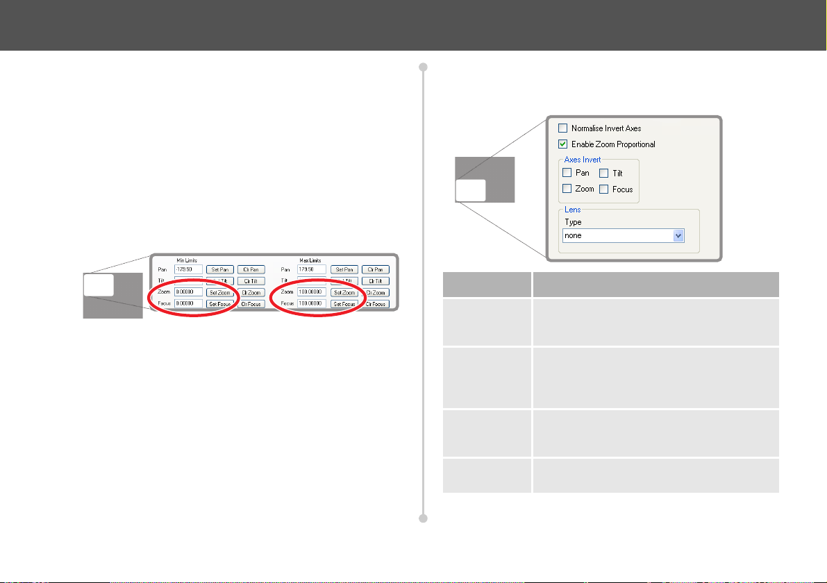
Setting the Servo Lens Soft Limits
Soft limits can also be applied to zoom and focus if a servo lens is
connected to the head. This is useful to restrict the range of the lens
drives away from the mechanical hard stops.
1. Move zoom and focus to the required minimum positions or enter
an encoder count value in the Min Limits field.
2. Click the Set Zoom and Set Focus buttons
3. Click Apply to store the new limits.
4. Repeat steps 1 to 3 to set the required maximum positions in the
Max Limits fields.
General Axis Configuration
The following settings can also be changed in the head configuration
window:
Setting Use
Normalise
Invert Axes
Enable Zoom
Proportional
Axes Invert Selecting a check box in this field reverses the
Lens Type Select the required lens type from the drop-
Select if the head is mounted upside down
from the ceiling. Pan and tilt axes are reversed
to give standard control on an inverted mount.
Select to enable the speed of pan and tilt
movement to be proportional to the zoom
angle (zoomed in slower, and zoomed out
faster).
direction of the axis when controlled using a
joystick.
down menu.
Click Apply to store and activate any configuration changes.
15

Head Configuration
Note
GP I/O Configuration
The function of the four data channels on the GP I/O socket of the head
are enabled and configured using ICE Tool. The channels can be
configured to function as inputs or outputs.
CAUTION! Risk of product damage. Ensure that the
auxiliary device connected to the GP I/O socket is
compatible with the input/output settings configured using
ICE Tool.
1. Right-click on the Gpio component and select Open.
2. The Gpio window opens. The four channels are labelled GPIO-0
to GPIO-3.
3. In the Direction fields, configure the required channels as outputs
or inputs by clicking Out or In.
4. To enable an output channel, click Turn O n for the required
channel. The button toggles to become a Tur n O ff function and
the status of the channel changes to ON.
If a channel is configured as an input, the Tur n On button is
not available.
5. Any configuration changes made remain in effect after the Gpio
window is closed .
16

Head Configuration
VR Configuration
On an ICE head with VR compatibility, ICE Tool is used to enable and
configure the VR settings. Changes can be made to the VR data output
standards.
1. Right-click on the Vri component and select Open.
2. The Vri window opens. The following configuration settings can be
changed:
a) An identification number can be assigned to a VR head in a
multi-camera system. This number is then transmitted as part
of the VR data packet. Enter a number in the Camera Id field.
b) To output the VR data as serial comms, click to select SERIAL
from the Output Comms Type drop-down menu. Click to
select the required data rate in the Serial Settings field.
c) To output the VR data on Ethernet, click to select UDP from
the Output Comms Type drop-down menu. Enter the
connection details of the VR hardware in the Receiver
Address and Receiver Port fields.
d) If the VR data output is not synchronised with a genlock signal,
select the Allow Free Running check box.
17

Head Configuration
e) To enable the head to start transmitting VR data, select the
Enable VR Tracking check box.
3. Click Apply to store and enable any configuration changes to take
effect.
Copying Configurations
The configuration settings on a head can be transferred to another
head of the same type. This saves time when setting up a system with
identical heads. It is also possible to transfer the configuration of just
one component of a head, such as the VR or Ethernet settings.
Copying Head Configuration
Right-click on the host ID of the head with the required
1.
configuration and select Copy Configuration.
2. Right-click on the host ID of the recipient head for the copied
configuration and select Paste Configuration.
3. When the confirmation window appears, click Yes to paste the
configuration into the head. Click No to abort the procedure.
Copying Component Configuration
Right-click on the required individual component of a head and
1.
select Copy Configuration. Configuration settings can be copied
and pasted from the Hcm, Head and Vri components.
2. Right-click on the correct component of the recipient head and
select Paste from the menu. When the confirmation window
appears, click Yes to confirm and paste the configuration file into
the recipient head, or No to abort.
18
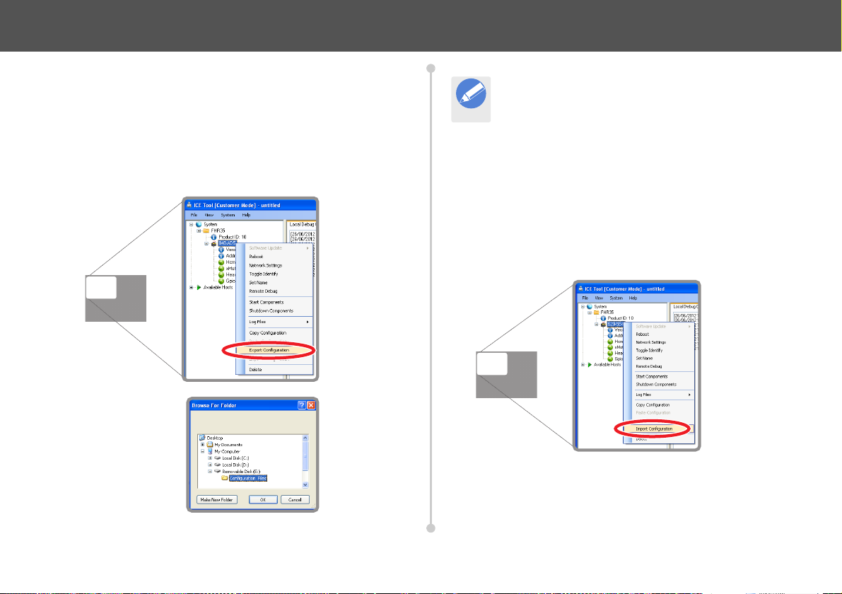
Exporting Configurations
Note
The configuration of a head or head component can be saved as a file
for future use with ICE Tool. The file can also be used to load on to
heads in another system.
Exporting Head Configuration
Right-click on the host ID of the head with the required
1.
configuration and select Export Configuration.
2. In the Browse For
Folder window
select a folder
location to store
the configuration
file and click Ok.
Head Configuration
Alternatively, use the Make New Folder button to create a
storage folder for the configuration file.
3. The configuration file is saved in the selected folder location and is
named using the host ID number of the head in the format HostID_config.xml.
Importing Head Configuration
Stored configuration files can be retrieved and loaded onto recipient
heads when required.
1. Right-click on the recipient head host ID and select Import
Configuration.
2. In the Open window, browse to the folder containing the required
configuration file.
19
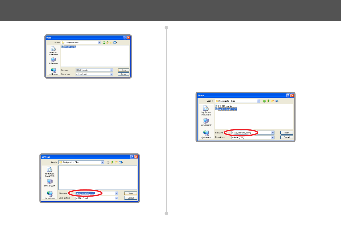
Head Configuration
3. Click to select the file and click Open.
4. When the confirmation window appears, click Yes to import the
configuration from the file into the device. Click No to abort the
procedure.
Exporting Component Configurations
1. Right-click on the required individual component of a head and
select Export Configuration. Configuration settings can be
exported from the Hcm, Head and Vri components.
2. In the Save As window select a folder location to store the
component configuration file and click Save.
3. The component configuration file will be saved in the selected
folder location and is named using the component name and host
ID number of the head in the format Component_Host-
ID_config.xml.
Importing Component Configurations
Right-click on the correct component of the recipient device and
1.
select Import Configuration.
2. In the Open window, browse to the folder containing the required
configuration file. Click to select the file and click Open.
3. When the confirmation window appears, click Yes to confirm and
paste the component configuration file into the recipient head
component. Click No to abort the procedure.
20


VAVinten Radamec
itec Group brand
Publication part No. V4096-4985/1
 Loading...