

Vinten Radamec
Control System
Operators Guide
V4009-4980
Robotic Camera Control Systems


VRC System
Operators Guide
Original Instructions
Publication Part No. V4009-4980 Issue 3.1

Copyright © Vitec Group plc 2009
All rights reserved throughout the world. No
part of this document may be stored in a
retrieval system. transmitted, copied or
reproduced in any way including, but not
limited to, photocopy, photograph, magnetic
or other record without the prior agreement
and permission in writing of Vitec Group plc.
Trademarks
Vinten Radamec Broadcast Robotics® and
Vinten® are registered trademarks of the
Vitec Group plc.
Wiindows® and Windows XP® are
registered trademarks of the Microsoft
Corporation.
Important information about this document
Information contained in this document is
subject to change. Camera Dynamics
Limited reserves the right, without notice, to
make changes in equipment design or
performance as progress in engineering,
manufacturing or technology may warrant.
Published by:
Technical Publications Department
Camera Dynamics Ltd
William Vinten Building
Western Way
Bury St Edmunds
Suffolk IP33 3TB
UK
Tel: +44 1284 752 121
Fax: +44 1284 750 560
Printed in Great Britain by DPS, Newmarket, Suffolk
Safety - Read This First
Understanding these instructions
English
The original instructions presented in this operators guide were written in English, and subsequently
translated into other languages. If you are unable to understand these instructions, contact Vinten
Radamec or your distributor to obtain a translation of the original instructions (EU Countries).
БЪЛГАРСКИ
Оригиналните инструкции, представени в настоящото ръководство на производителя, бяха
написани на английски език, а след това - преведени на други езици. Ако не разбирате тези
езици, свържете се с Vinten Radamec или с Вашия дистрибутор, за да получите оригиналните
инструкции (за страните от Европейския съюз).
Česky
Pokyny uvedené v této operátorské příručce byly původně
přelo_eny do ostatních jazyků. Nerozumíte-li těmto pokynům, kontaktujte společnost Vinten Radamec
nebo svého distributora, abyste získali překlad originálních pokynů (členské státy EU).
Danish
De originale instruktioner, der præsenteres i denne betjeningsvejledning, er skrevet på engelsk og
derefter oversat til andre sprog. Hvis du ikke forstår disse instruktioner bedes du kontakte Vinten
Radamec eller vor forhandler for at få en oversættelse af de originale instruktioner (EU-lande).
Deutsch
Die Originalanleitung in diesem Bedienungshandbuch wurde auf Englisch verfasst und anschließend
in andere Sprachen übersetzt. Bei Verständnisproblemen in einer der übersetzten Sprachen
kontaktieren Sie bitte Vinten Radamec oder Ihren Fachhändler; dort erhalten Sie eine Übersetzung
der ursprünglichen Anleitung (EU-Staaten).
Eesti
Käesoleva kasutajajuhendi algtekst on koostatud inglise keeles ning seejärel tõlgitud teistesse
keeltesse. Kui juhend osutub teie jaoks arusaamatuks, võtke juhendi emakeelse tõlke hankimiseks
ühendust Vinten Radameci või kohaliku esindajaga (Euroopa Liidu riigid).
Ελληνικά
Οι αρχικές οδηγίες αυτού του οδηγού για το χειριστή συντάχθηκαν στα Αγγλικά και μεταφράστηκαν στη
συνέχεια σε άλλες γλώσσες. Εάν δυσκολεύεστε να καταλάβετε αυτές τις οδηγίες, επικοινωνήστε με τη
Vinten Radamec ή το
Español
Las instrucciones originales que se indican en esta guía del operador se han redactado en inglés y
posteriormente se han traducido a otros idiomas. Si no entiende estas instrucciones, póngase en
contacto con Vinten Radamec o con su distribuidor para obtener una traducción de las instrucciones
originales (para países de la UE).
Français
Les instructions originales présentées dans ce guide d'utilisation ont été écrites en anglais puis
traduites dans d'autres langues. Si vous ne comprenez pas ces instructions, contactez Vinten
Radamec ou votre revendeur pour obtenir une traduction des instructions originales (pour les pays de
l'UE).
Gaeilge
Scríobhadh na treoracha bunaidh don treoirleabhar oibritheora seo as Béarla, agus aistríodh iad go
teangacha eile ina dhiaidh sin. Mura bhfuil tú in ann na treoracha seo a thuiscint, téigh i dteagmháil le
Vinten Radamec nó le do dháileoir, chun aistriúchán de na treoracha bunaidh a fháil (Tíortha an AE).
Italiano
Le istruzioni originali presentate in questa guida per l'operatore sono in lingua inglese e
successivamente tradotte nelle altre lingue. Qualora le istruzioni non fossero disponibili nella lingua
desiderata, potete contattare Vinten Radamec o il vostro distributore per ricevere la traduzione delle
istruzioni originali (Paesi UE).
διανομέα σας για να λάβετε μια μετάφραση των αρχικών οδηγιών (Χώρες ΕΕ).
napsány anglicky a následně byly
Publication Part No. V4009-4980 Issue 3.1 3
Latviešu
Šajā operatora rokasgrāmatā iekļautie norādījumi sākotnēji tika sarakstīti angļu valodā un pēc tam
pārtulkoti citās valodās. Ja nesaprotat šos norādījumus svešvalodā, sazinieties ar Vinten Radamec vai
tirgotāju, lai saņemtu norādījumu tulkojumu (kādā no ES dalībvalstu valodām).
Lietuvių
Šiame operatoriaus vadove pristatomos pirminės instrukcijos parašytos anglų kalba ir vėliau išverstos
į kitas kalbas. Jei šių instrukcijų nesuprantate, susisiekite su „Vinten Radamec“arba savo platintoju ir
gaukite pirminių instrukcijų vertimą (ES šalies kalba).
Magyar
A kezeloi útmutatóban található utasítások angol nyelven íródtak, és utólag fordították azokat más
nyelvekre. Ha nem érti ezen utasításokat, kérjük, vegye fel a kapcsolatot a Vinten Radamecnel vagy
a helyi képviselettel, és igényelje az eredeti utasítások fordítását (EU országok).
Malti
L-istruzzjonijiet originali ippreżentati f'din il-gwida ta' operaturi kienu miktuba bl-Ingliż, u sussegwentement maqluba fl-lingwi ohra. Jekk ma tistax tifhem dawn l-istruzzjonijiet, ikkuntattja lil Vinten Radamec
jew id-distributur tieghek biex tikseb traduzzjoni ta' l-istruzzjonijiet originali (Pajjiżi ta' UE).
Nederlands
De oorspronkelijke instructies in deze bedieningshandleiding zijn geschreven in het Engels en
vervolgens in andere talen vertaald. Als het onmogelijk is deze instructies te begrijpen, neemt u
contact op met Vinten Radamec of met uw distributeur om een vertaling te bemachtigen van de
oorspronkelijke instructies (EG-landen).
Polski
Oryginalne instrukcje zamieszczone w niniejszym podręczniku operatora zostały napisane w języku
angielskim, a następnie przetłumaczone na inne języki. Jeśli nie rozumieją Państwo tych instrukcji,
prosimy skontaktować się z siedzibą lub dystrybutorem Vinten Radamec, aby uzyskać tłumaczenie
oryginalnych instrukcji (kraje UE).
Português
As instruções originais apresentadas no guia do operador foram escritas em Inglês e traduzidas para
outros idiomas. Se não conseguir compreender estas instruções contacte a Vinten Radamec ou o seu
distribuidor para obter a tradução das instruções originais (Países da UE).
Română
Instrucţiunile originale prezentate în acest ghid pentru operatori au fost scrise în limba engleză, şi
traduse ulterior în alte limbi. În cazul în care nu înţelegeţi aceste instrucţiuni, contactaţi Vinten Radamec sau distribuitorul dumneavoastră pentru a obţine o traducere a instrucţiunilor originale (Ţările
UE).
Slovensky
Pôvodné pokyny, uvedené v tomto návode na obsluhu, boli napísané v anglictine a následne
preložené do iných jazykov. Ak nerozumiete týmto pokynom, obrátte sa na spolocnost Vinten
Radamec alebo vášho distribútora, aby vám zaslal preklad originálnych pokynov (krajiny EÚ).
Slovenščina
Originalno besedilo teh navodil za uporabo je bilo napisano v angleščini in prevedeno v ostale jezike.
Če ne razumete teh navodil, se obrnite na podjetje Vinten Radamec ali lokalnega zastopnika, ki vam
bo posredoval originalna navodila (velja za dr_ave EU).
Suomi
Tähän käyttäjän oppaaseen sisältyvät ohjeet on kirjoitettu alun perin englanniksi ja käännetty sitten
muille kielille. Ellet ymmärrä näitä ohjeita, ota yhteyttä Vinten Radameciin tai jälleenmyyjään ja pyydä
alkuperäisten ohjeiden käännöstä (EU-maat).
Svenska
Instruktionerna i denna handbok skrevs ursprungligen på engelska och har sedan översatts till flera
språk. Om du inte förstår dessa instruktioner, kontakta Vinten Radamec eller din återförsäljare för en
ny översättning av originalinstruktionerna (EU-länder).
4 VRC System Operators Guide
Safety Guidelines
Warning symbols in this operators guide
Where there is a risk of personal injury or injury to others, comments appear highlighted
by the word WARNING!—supported by the warning triangle symbol.
Where there is a risk of damage to the product, associated equipment, process or
surroundings, comments appear highlighted by the word CAUTION!
Warning symbols on the product
On encountering the warning
triangle and open book symbols it is
imperative that you consult this
operators guide before using this
product or attempting any
adjustment or repair.
Publication Part No. V4009-4980 Issue 3.1 5

Important safety instructions
1 Take heed of warnings and instructions
You should read all of the safety instructions
before operating the equipment. Retain this
operators guide for future reference and adhere to
all warnings in the guide or on the equipment.
Do not attempt to operate this equipment if
you do not understand how to operate it.
2. Usage Statement
Do not use this product for any other purpose
other than that specified in this usage statement.
The VRC System is designed for use within
television studios to remotely control cameras,
pan/tilt heads and pedestals. Only trained
television camera operators should use this
product. This product is not suitable for use
outdoors in an exposed environment
3. Water, moisture and dust
Protect the product from water, moisture and
dust. The presence of electricity near water can be
dangerous. Do not use the product near water and
take care that liquids are not spilled onto the
equipment.
4. Climate
The equipment should not be used outside the
operating limits. Refer to the Technical
Specification in the Technical Guide for the
operating range of the equipment.
5. Cleaning
We encourage regular cleaning of the product.
• Do not use oil or grease on any exposed part of
the equipment. This is unnecessary and traps dirt
which acts as an abrasive.
• Do not use solvent or oil based cleaners,
abrasives or wire brushes to remove
accumulations of dirt as these damage the
protective surfaces. To clean mechanical
surfaces, use only detergent based cleaners.
• External electrical connection ports should only
be cleaned with a semi-stiff brush or using a
vacuum cleaner.
6 Servicing
You should not attempt to service the equipment.
Contact Camera Dynamics Ltd or your local
distributor to arrange servicing. Refer to the
Technical Guide for information on regular
maintenance.
7. Notes about Robotic equipment
Display prominent warning signs in studios,
alerting personnel that robotic equipment is
present and may move without warning.
Ensure personnel remain a minimum of 1 m (40
inches) clear of robotic equipment in use.
Operators must familiarise themselves with the
resulting working envelope of robotic products
including all ancillary equipment (lens, zoom and
focus controls, viewfinder, prompter etc.), to
prevent inadvertent collisions.
Only operate robotic products remotely when you
can see them to avoid harm to personnel and
collisions with obstacles and other hazards.
8. Power sources
Only connect the equipment to a power supply of
the type described in the Technical Guide or as
marked on the equipment.
9. Cables
Always ensure that all power and auxiliary
communications cables are routed so that they do
not present any danger to personnel. Take care
when routing cables in areas where robotic
equipment is in use.
This product is designed and manufactured to meet strict quality and safety standards. However, it is
important that you are aware of the following installation and operation precautions. Many of these
instructions are commonsense precautions, but for your own safety and to ensure that you do not damage
the equipment, we recommend that you read them.
6 VRC System Operators Guide

Certificates and Compliances
This product conforms to the following European Directives:
2006/42/EC (CE Marking Directive)
73/23/EEC (Low Voltage Directive)
2004/108/EC (Electromagnetic Compatibility Directive)
This product has been tested and found compliant to the following test standards:
EMC:
EN 61000-6-4:2001
EN 61000-6-2:2001
EN 61000-3-2:2000
EN 61000-3-3:1995 (+A1)
LVD:
EN 60950-1:2006
Other Certification
FCC:
CFR 47:2006 Class A
Publication Part No. V4009-4980 Issue 3.1 7

Caring for the environment by recycling
Recycling old electrical and electronic equipment
This symbol on the product or on its packaging indicates that this product must not be
treated as household waste (applicable in the European Union and European countries
with separate collection systems). It shall be handed over to the applicable collection
point for the recycling of electrical and electronic equipment. Please visit
www.vintenradamec.com/support/WEEE Information for details.
By ensuring this product is disposed of correctly, you will help prevent potentially
negative consequences for the environment and human health, and help conserve
natural resources.
About this manual
This m a n u a l is intend ed as a guide to television camera operators with a working knowledge of
broadcasting robotic equipment and systems. This manual contains information about using the VRC
Control Panel and the VRC software that is operated using a touch-screen monitor to remotely control
cameras, pan/tilt heads and pedestal.
The VRC system can be supplied with various Control Panel options and is configured to suit
customer specific requirements. Therefore this guide may include referen ces to functio ns that are not
applicable to your system.
For information on system installation and configuration, technical support and troubleshooting,
please refer to the VRC Technical Guide (Publication Part Number V4009-4990).
Technical specification
Software
VRC software . . . . . . . . . . . . . . . . . . . . . . . . . . . . . . . . . . . . . . . . . . . . . . . . . . . . . . . . . . . . . . . . .version 1.17
Refer to the VRC Technical Guide (Publication Part number V4009-4990) for the technical
specifications of the VRC Control Panels and associated system equipment.
8 VRC System Operators Guide

Contents
Page
Safety - Read This First . . . . . . . . . . . . . . . . . . . . . . . . . . . . . . . . . . . . . . . . . . . . . . . . . . . . . . . . . . . . . . . . 3
Understanding these instructions . . . . . . . . . . . . . . . . . . . . . . . . . . . . . . . . . . . . . . . . . . . . . . . . . . . . . 3
Safety Guidelines . . . . . . . . . . . . . . . . . . . . . . . . . . . . . . . . . . . . . . . . . . . . . . . . . . . . . . . . . . . . . . . . . 5
Important safety instructions . . . . . . . . . . . . . . . . . . . . . . . . . . . . . . . . . . . . . . . . . . . . . . . . . . . . . . . . . 6
Certificates and Compliances . . . . . . . . . . . . . . . . . . . . . . . . . . . . . . . . . . . . . . . . . . . . . . . . . . . . . . . . . . . 7
Caring for the environment by recycling . . . . . . . . . . . . . . . . . . . . . . . . . . . . . . . . . . . . . . . . . . . . . . . . . . 8
About this manual. . . . . . . . . . . . . . . . . . . . . . . . . . . . . . . . . . . . . . . . . . . . . . . . . . . . . . . . . . . . . . . . . . . . . 8
Technical specification. . . . . . . . . . . . . . . . . . . . . . . . . . . . . . . . . . . . . . . . . . . . . . . . . . . . . . . . . . . . . . . . . 8
Section 1 Getting Started
Getting Started . . . . . . . . . . . . . . . . . . . . . . . . . . . . . . . . . . . . . . . . . . . . . . . . . . . . . . . . . . . . . . . . . . . . . . 14
Starting the controller . . . . . . . . . . . . . . . . . . . . . . . . . . . . . . . . . . . . . . . . . . . . . . . . . . . . . . . . . . . . . 14
Starting the VRC server . . . . . . . . . . . . . . . . . . . . . . . . . . . . . . . . . . . . . . . . . . . . . . . . . . . . . . . . . . . 14
Starting the User interface . . . . . . . . . . . . . . . . . . . . . . . . . . . . . . . . . . . . . . . . . . . . . . . . . . . . . . . . . 15
User Accounts. . . . . . . . . . . . . . . . . . . . . . . . . . . . . . . . . . . . . . . . . . . . . . . . . . . . . . . . . . . . . . . . . . . 16
Creating a user account . . . . . . . . . . . . . . . . . . . . . . . . . . . . . . . . . . . . . . . . . . . . . . . . . . . . . . 16
Editing a user account . . . . . . . . . . . . . . . . . . . . . . . . . . . . . . . . . . . . . . . . . . . . . . . . . . . . . . . 17
Deleting a user account . . . . . . . . . . . . . . . . . . . . . . . . . . . . . . . . . . . . . . . . . . . . . . . . . . . . . . 17
Calibrating the touch-screen . . . . . . . . . . . . . . . . . . . . . . . . . . . . . . . . . . . . . . . . . . . . . . . . . . . . . . . . 18
Section 2 - Control Panel Operation
VRC control panel . . . . . . . . . . . . . . . . . . . . . . . . . . . . . . . . . . . . . . . . . . . . . . . . . . . . . . . . . . . . . . . . . . . . 19
Single joystick control panel . . . . . . . . . . . . . . . . . . . . . . . . . . . . . . . . . . . . . . . . . . . . . . . . . . . . . . . . 19
Dual joystick control panel . . . . . . . . . . . . . . . . . . . . . . . . . . . . . . . . . . . . . . . . . . . . . . . . . . . . . . . . . 19
Operating the control panel. . . . . . . . . . . . . . . . . . . . . . . . . . . . . . . . . . . . . . . . . . . . . . . . . . . . . . . . . 19
Publication Part No. V4009-4980 Issue 3.1 9

Contents (Cont) Page
Switching on the panel . . . . . . . . . . . . . . . . . . . . . . . . . . . . . . . . . . . . . . . . . . . . . . . . . . . . . . . 19
Configuring the operation of the control panel . . . . . . . . . . . . . . . . . . . . . . . . . . . . . . . . . . . . . 19
Locking the control panel . . . . . . . . . . . . . . . . . . . . . . . . . . . . . . . . . . . . . . . . . . . . . . . . . . . . . 19
Remotely operating a Camera . . . . . . . . . . . . . . . . . . . . . . . . . . . . . . . . . . . . . . . . . . . . . . . . . . . . . . 20
Camera preview . . . . . . . . . . . . . . . . . . . . . . . . . . . . . . . . . . . . . . . . . . . . . . . . . . . . . . . . . . . . 20
Pan/Tilt/Zoom joystick. . . . . . . . . . . . . . . . . . . . . . . . . . . . . . . . . . . . . . . . . . . . . . . . . . . . . . . . 21
Focus control . . . . . . . . . . . . . . . . . . . . . . . . . . . . . . . . . . . . . . . . . . . . . . . . . . . . . . . . . . . . . . 21
Black level and iris CCU controls . . . . . . . . . . . . . . . . . . . . . . . . . . . . . . . . . . . . . . . . . . . . . . . 21
Cut, Fade and Stop buttons . . . . . . . . . . . . . . . . . . . . . . . . . . . . . . . . . . . . . . . . . . . . . . . . . . . 21
Fade Time control. . . . . . . . . . . . . . . . . . . . . . . . . . . . . . . . . . . . . . . . . . . . . . . . . . . . . . . . . . . 22
Wash wipe . . . . . . . . . . . . . . . . . . . . . . . . . . . . . . . . . . . . . . . . . . . . . . . . . . . . . . . . . . . . . . . . 22
X4 . . . . . . . . . . . . . . . . . . . . . . . . . . . . . . . . . . . . . . . . . . . . . . . . . . . . . . . . . . . . . . . . . . . . . . . 22
Remotely operating a Pedestal. . . . . . . . . . . . . . . . . . . . . . . . . . . . . . . . . . . . . . . . . . . . . . . . . . . . . . 22
Joystick enable . . . . . . . . . . . . . . . . . . . . . . . . . . . . . . . . . . . . . . . . . . . . . . . . . . . . . . . . . . . . . 22
XY/Height joystick. . . . . . . . . . . . . . . . . . . . . . . . . . . . . . . . . . . . . . . . . . . . . . . . . . . . . . . . . . . 23
Pan follow . . . . . . . . . . . . . . . . . . . . . . . . . . . . . . . . . . . . . . . . . . . . . . . . . . . . . . . . . . . . . . . . . 23
Bumper disable. . . . . . . . . . . . . . . . . . . . . . . . . . . . . . . . . . . . . . . . . . . . . . . . . . . . . . . . . . . . . 23
RP2A control functions . . . . . . . . . . . . . . . . . . . . . . . . . . . . . . . . . . . . . . . . . . . . . . . . . . . . . . . 23
Section 3 - VRC System User Interface
VRC System User Interface . . . . . . . . . . . . . . . . . . . . . . . . . . . . . . . . . . . . . . . . . . . . . . . . . . . . . . . . . . . . 25
Workspace . . . . . . . . . . . . . . . . . . . . . . . . . . . . . . . . . . . . . . . . . . . . . . . . . . . . . . . . . . . . . . . . . . . . . 25
Camera Selection and Status bar. . . . . . . . . . . . . . . . . . . . . . . . . . . . . . . . . . . . . . . . . . . . . . . . . . . . 26
Functions and menus . . . . . . . . . . . . . . . . . . . . . . . . . . . . . . . . . . . . . . . . . . . . . . . . . . . . . . . . . . . . . 27
Menu. . . . . . . . . . . . . . . . . . . . . . . . . . . . . . . . . . . . . . . . . . . . . . . . . . . . . . . . . . . . . . . . . . . . . 27
Edit . . . . . . . . . . . . . . . . . . . . . . . . . . . . . . . . . . . . . . . . . . . . . . . . . . . . . . . . . . . . . . . . . . . . . . 27
Stop . . . . . . . . . . . . . . . . . . . . . . . . . . . . . . . . . . . . . . . . . . . . . . . . . . . . . . . . . . . . . . . . . . . . . 28
10 VRC System Operators Guide

Contents (Cont) Page
Cut . . . . . . . . . . . . . . . . . . . . . . . . . . . . . . . . . . . . . . . . . . . . . . . . . . . . . . . . . . . . . . . . . . . . . . 28
Fade . . . . . . . . . . . . . . . . . . . . . . . . . . . . . . . . . . . . . . . . . . . . . . . . . . . . . . . . . . . . . . . . . . . . . 29
Fade or Cut multiple shots . . . . . . . . . . . . . . . . . . . . . . . . . . . . . . . . . . . . . . . . . . . . . . . . . . . . 29
Store . . . . . . . . . . . . . . . . . . . . . . . . . . . . . . . . . . . . . . . . . . . . . . . . . . . . . . . . . . . . . . . . . . . . . 29
Virtual stick . . . . . . . . . . . . . . . . . . . . . . . . . . . . . . . . . . . . . . . . . . . . . . . . . . . . . . . . . . . . . . . . 30
Sequence of shots . . . . . . . . . . . . . . . . . . . . . . . . . . . . . . . . . . . . . . . . . . . . . . . . . . . . . . . . . . 30
Focus . . . . . . . . . . . . . . . . . . . . . . . . . . . . . . . . . . . . . . . . . . . . . . . . . . . . . . . . . . . . . . . . . . . . 32
Page up/Page down . . . . . . . . . . . . . . . . . . . . . . . . . . . . . . . . . . . . . . . . . . . . . . . . . . . . . . . . . 32
Opts menu . . . . . . . . . . . . . . . . . . . . . . . . . . . . . . . . . . . . . . . . . . . . . . . . . . . . . . . . . . . . . . . . 33
Section 4 - Targeting Pedestals
Targeting the pedestals . . . . . . . . . . . . . . . . . . . . . . . . . . . . . . . . . . . . . . . . . . . . . . . . . . . . . . . . . . . . . . . 34
Fusion pedestal. . . . . . . . . . . . . . . . . . . . . . . . . . . . . . . . . . . . . . . . . . . . . . . . . . . . . . . . . . . . . . . . . . 34
Pedestal orientation . . . . . . . . . . . . . . . . . . . . . . . . . . . . . . . . . . . . . . . . . . . . . . . . . . . . . . . . . 34
Targeting the pedestal . . . . . . . . . . . . . . . . . . . . . . . . . . . . . . . . . . . . . . . . . . . . . . . . . . . . . . . 34
SP-2000 pedestal . . . . . . . . . . . . . . . . . . . . . . . . . . . . . . . . . . . . . . . . . . . . . . . . . . . . . . . . . . . . . . . . 36
RP2A pedestal . . . . . . . . . . . . . . . . . . . . . . . . . . . . . . . . . . . . . . . . . . . . . . . . . . . . . . . . . . . . . . . . . . 37
Section 5 - Shots and Shows
Shots and shows. . . . . . . . . . . . . . . . . . . . . . . . . . . . . . . . . . . . . . . . . . . . . . . . . . . . . . . . . . . . . . . . . . . . . 38
Show management. . . . . . . . . . . . . . . . . . . . . . . . . . . . . . . . . . . . . . . . . . . . . . . . . . . . . . . . . . . . . . . 38
Creating a new show . . . . . . . . . . . . . . . . . . . . . . . . . . . . . . . . . . . . . . . . . . . . . . . . . . . . . . . . 38
Loading a show. . . . . . . . . . . . . . . . . . . . . . . . . . . . . . . . . . . . . . . . . . . . . . . . . . . . . . . . . . . . . 38
List all shows . . . . . . . . . . . . . . . . . . . . . . . . . . . . . . . . . . . . . . . . . . . . . . . . . . . . . . . . . . . . . . 39
Deleting a show . . . . . . . . . . . . . . . . . . . . . . . . . . . . . . . . . . . . . . . . . . . . . . . . . . . . . . . . . . . . 39
Creating the home or target shot . . . . . . . . . . . . . . . . . . . . . . . . . . . . . . . . . . . . . . . . . . . . . . . . . . . . 39
Adding shots to a show. . . . . . . . . . . . . . . . . . . . . . . . . . . . . . . . . . . . . . . . . . . . . . . . . . . . . . . . . . . . 41
Publication Part No. V4009-4980 Issue 3 11

Shot status colour codes. . . . . . . . . . . . . . . . . . . . . . . . . . . . . . . . . . . . . . . . . . . . . . . . . . . . . . . . . . . 44
Using shots . . . . . . . . . . . . . . . . . . . . . . . . . . . . . . . . . . . . . . . . . . . . . . . . . . . . . . . . . . . . . . . . . . . . . 45
Fade . . . . . . . . . . . . . . . . . . . . . . . . . . . . . . . . . . . . . . . . . . . . . . . . . . . . . . . . . . . . . . . . . . . . . 45
Cut . . . . . . . . . . . . . . . . . . . . . . . . . . . . . . . . . . . . . . . . . . . . . . . . . . . . . . . . . . . . . . . . . . . . . . 46
Stopping A Fade Or Cut . . . . . . . . . . . . . . . . . . . . . . . . . . . . . . . . . . . . . . . . . . . . . . . . . . . . . . 46
Fade Timer Control. . . . . . . . . . . . . . . . . . . . . . . . . . . . . . . . . . . . . . . . . . . . . . . . . . . . . . . . . . 46
Edit menu . . . . . . . . . . . . . . . . . . . . . . . . . . . . . . . . . . . . . . . . . . . . . . . . . . . . . . . . . . . . . . . . . . . . . . 46
Latched delete . . . . . . . . . . . . . . . . . . . . . . . . . . . . . . . . . . . . . . . . . . . . . . . . . . . . . . . . . . . . . 47
Latched time . . . . . . . . . . . . . . . . . . . . . . . . . . . . . . . . . . . . . . . . . . . . . . . . . . . . . . . . . . . . . . . 48
Name . . . . . . . . . . . . . . . . . . . . . . . . . . . . . . . . . . . . . . . . . . . . . . . . . . . . . . . . . . . . . . . . . . . . 48
Time . . . . . . . . . . . . . . . . . . . . . . . . . . . . . . . . . . . . . . . . . . . . . . . . . . . . . . . . . . . . . . . . . . . . . 48
Delete . . . . . . . . . . . . . . . . . . . . . . . . . . . . . . . . . . . . . . . . . . . . . . . . . . . . . . . . . . . . . . . . . . . . 48
Resave . . . . . . . . . . . . . . . . . . . . . . . . . . . . . . . . . . . . . . . . . . . . . . . . . . . . . . . . . . . . . . . . . . . 49
Swap. . . . . . . . . . . . . . . . . . . . . . . . . . . . . . . . . . . . . . . . . . . . . . . . . . . . . . . . . . . . . . . . . . . . . 49
Return. . . . . . . . . . . . . . . . . . . . . . . . . . . . . . . . . . . . . . . . . . . . . . . . . . . . . . . . . . . . . . . . . . . . 49
Section 6 - Putting it all together (Tutorial)
Putting it all together . . . . . . . . . . . . . . . . . . . . . . . . . . . . . . . . . . . . . . . . . . . . . . . . . . . . . . . . . . . . . . . . . 50
Blocking additional shots . . . . . . . . . . . . . . . . . . . . . . . . . . . . . . . . . . . . . . . . . . . . . . . . . . . . . . . . . . 51
Air time philosophy . . . . . . . . . . . . . . . . . . . . . . . . . . . . . . . . . . . . . . . . . . . . . . . . . . . . . . . . . . . . . . . 52
Cueing . . . . . . . . . . . . . . . . . . . . . . . . . . . . . . . . . . . . . . . . . . . . . . . . . . . . . . . . . . . . . . . . . . . 52
Trimming . . . . . . . . . . . . . . . . . . . . . . . . . . . . . . . . . . . . . . . . . . . . . . . . . . . . . . . . . . . . . . . . . . 52
Tracking . . . . . . . . . . . . . . . . . . . . . . . . . . . . . . . . . . . . . . . . . . . . . . . . . . . . . . . . . . . . . . . . . . 53
Sample news show rundown . . . . . . . . . . . . . . . . . . . . . . . . . . . . . . . . . . . . . . . . . . . . . . . . . . . . . . . 53
12 VRC System Operators Guide

Section 7 - Configuring the VRC System
Configuring the VRC system . . . . . . . . . . . . . . . . . . . . . . . . . . . . . . . . . . . . . . . . . . . . . . . . . . . . . . . . . . . 55
Grid display options . . . . . . . . . . . . . . . . . . . . . . . . . . . . . . . . . . . . . . . . . . . . . . . . . . . . . . . . . . . . . . 55
Stick settings. . . . . . . . . . . . . . . . . . . . . . . . . . . . . . . . . . . . . . . . . . . . . . . . . . . . . . . . . . . . . . . . . . . . 57
Panel options . . . . . . . . . . . . . . . . . . . . . . . . . . . . . . . . . . . . . . . . . . . . . . . . . . . . . . . . . . . . . . . . . . . 58
Camera control . . . . . . . . . . . . . . . . . . . . . . . . . . . . . . . . . . . . . . . . . . . . . . . . . . . . . . . . . . . . . . . . . . 60
Shot options . . . . . . . . . . . . . . . . . . . . . . . . . . . . . . . . . . . . . . . . . . . . . . . . . . . . . . . . . . . . . . . . . . . . 60
Shot preferences. . . . . . . . . . . . . . . . . . . . . . . . . . . . . . . . . . . . . . . . . . . . . . . . . . . . . . . . . . . . . . . . . 61
Section 8 - Database Scheduled Service
Database Schedule Service . . . . . . . . . . . . . . . . . . . . . . . . . . . . . . . . . . . . . . . . . . . . . . . . . . . . . . . . 62
Section 9- Parts List
Parts list . . . . . . . . . . . . . . . . . . . . . . . . . . . . . . . . . . . . . . . . . . . . . . . . . . . . . . . . . . . . . . . . . . . . . . . 67
Publication Part No. V4009-4980 Issue 3.1 13
Getting Started
The Vinten Radamec Control (VRC) System enables an operator to remotely control cameras,
pedestals, and pan and tilt heads. There are a number of VRC system variations, designed to ensure
compatibility with current Fusion products and, Radamec and AutoCam robotic products.
The VRC controller system includes a Windows XP computer with keyboard and mouse, touchscreen control monitor and control panel. In most applications a video switcher and preview monitor
are also installed.
WARNING!
The VRC system should only be used by experienced television camera
operators with a working knowledge of broadcasting robotic equipment
and systems.
Starting the controller
During normal operation the controller is left powered on. However, if the server has been powered
down, turn on the power at the controller and at the touch-screen monitor. The controller will perform
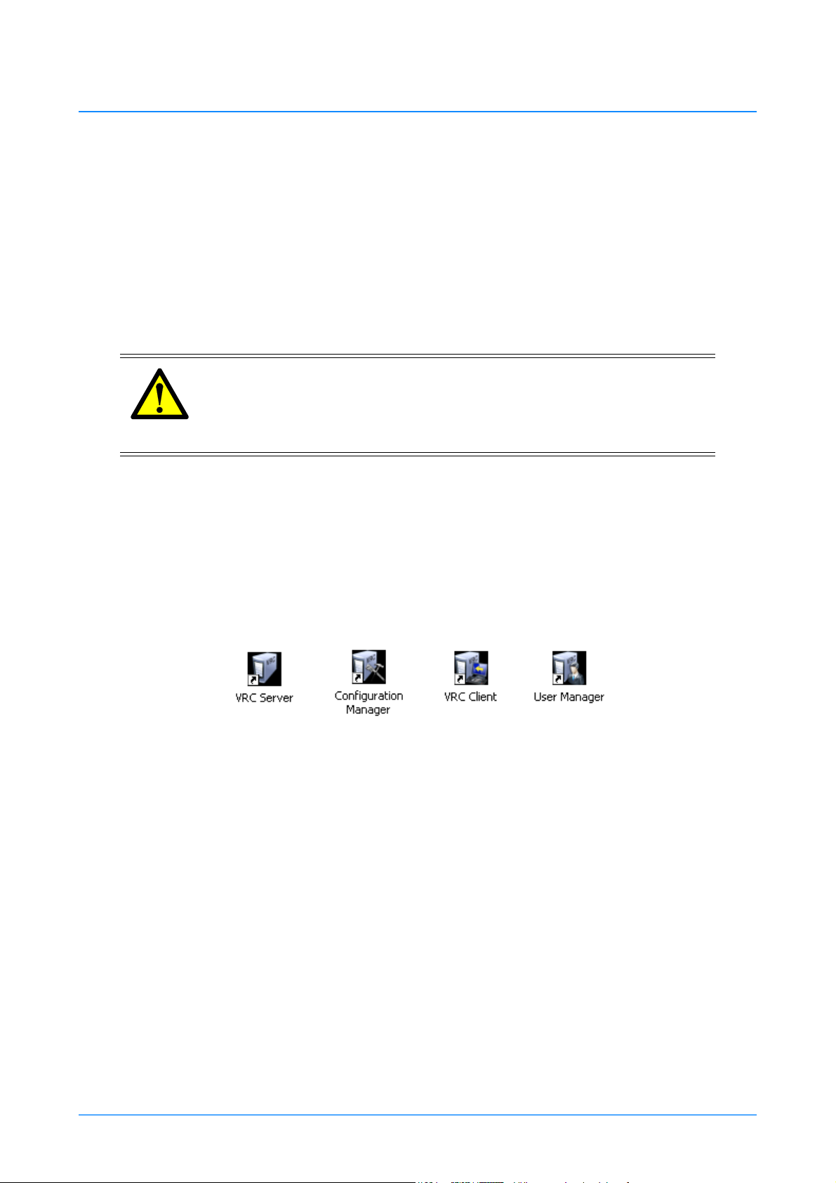
a normal Windows XP boot up and display the start up screen with the VRC short cut icons on the
desktop (Figure 1).
Figure 1 VRC system desktop icons
Starting the VRC server
The VRC Server application is the communication interface to the pedestals, heads and cameras in
the system. The VRC Server must be running at all times. Double click on the VRC Server icon to
launch the VRC Server window (Figure 2). Verify that the server commands scroll through the
window continuously.
14 VRC System Operators Guide
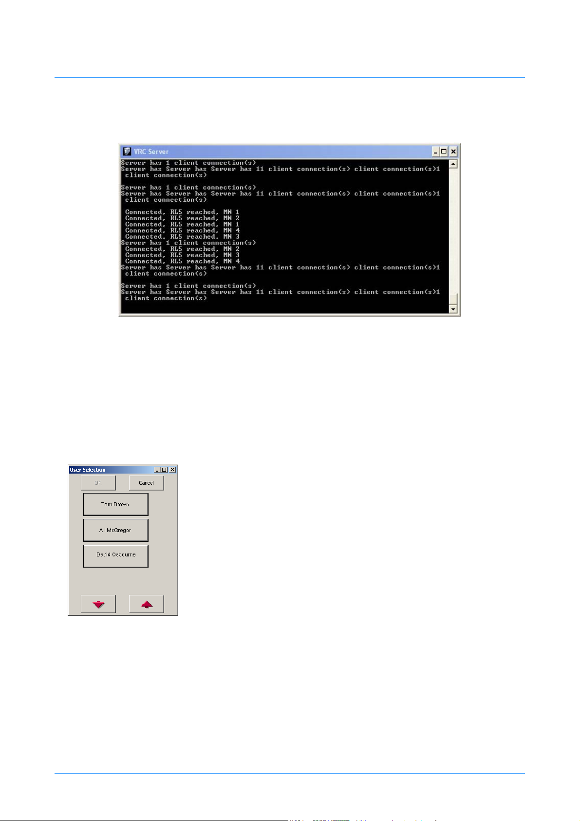
Figure 2 VRC server window
Figure 3 User Selection dialog
Note that when the VRC system is initialised, the lights on the pedestals will flash (if the pedestals
are in Auto mode (robotic control) and any heads that were left in Manual mode will automatically
switch to Auto mode (robotic control). The VRC Server window can be minimized or left running
behind the User Interface window.
Starting the User interface
The User Interface window provides all the functions for
operators to control the robotic pedestals and heads, and allows
operators to create shows using preprogrammed movements. All
users must have a user account before attempting to logon onto
the VRC system (see User Accounts on page 16).
To launch the User Interface, double click the VRC Client icon
on the desktop. The User Selection dialog appears (Figure 3).
Select your user login from the list and then click OK. Use the
Up and Down arrow keys to scroll through the list of users if
needed.
Publication Part No. V4009-4980 Issue 3.1 15
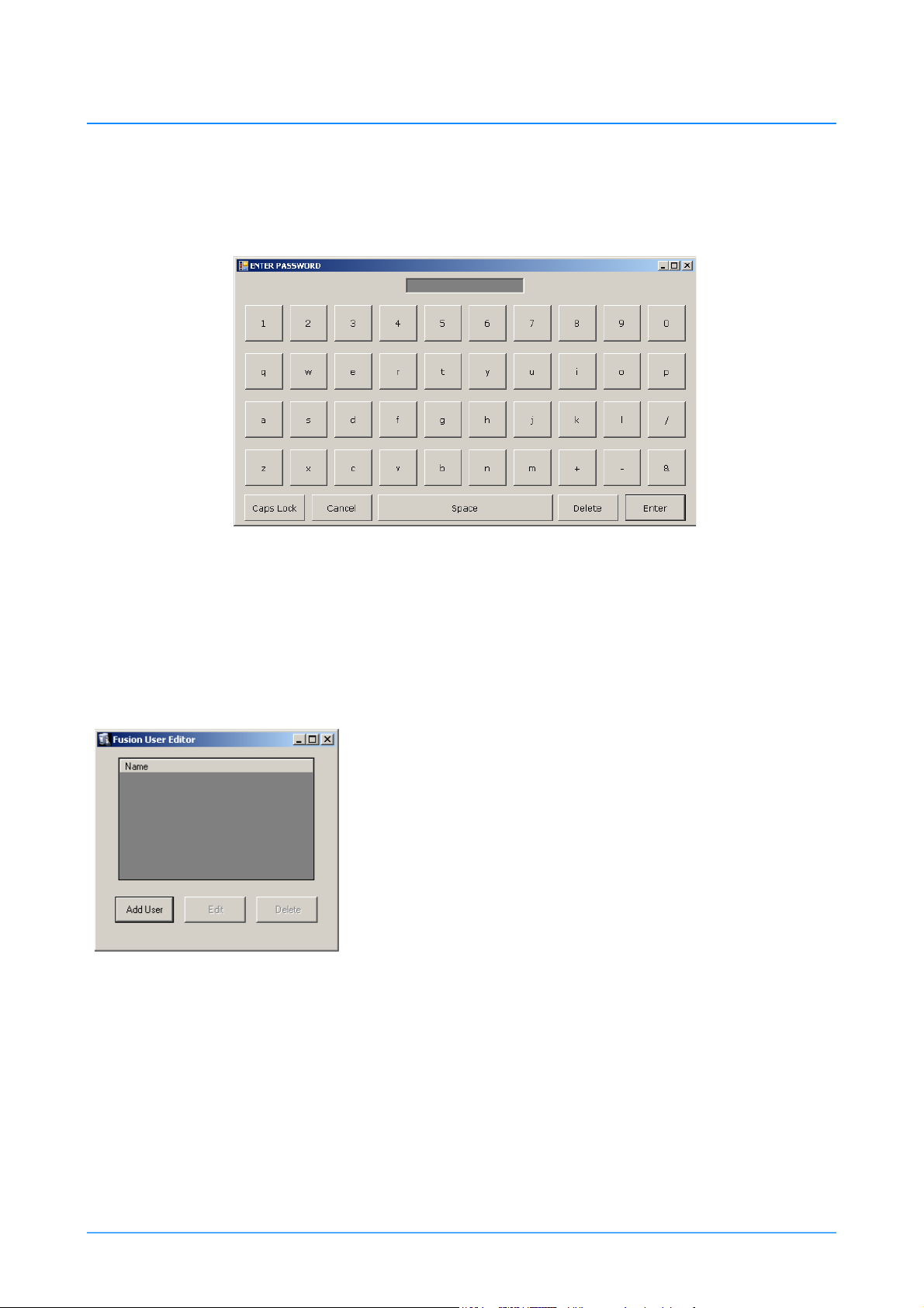
When you have selected your user login, the Enter Password dialog appears (Figure 4). Type in your
Figure 5 Fusion User Editor dialog
password and select ENTER.
Figure 4 Enter Password dialog
When the password has been entered and accepted, the VRC User Interface is launched and the
workspace appears (Figure 9).
User Accounts
The User Editor application s used to add or edit a user
account. The User Manager shortcut can be found on the
desktop or in the current version folder on the desktop.
1.Double click on the User Manager shortcut. The Fusion User
Editor dialog appears (Figure 5). This dialog lets you add new
accounts, and edit and delete existing user accounts.
Creating a user account
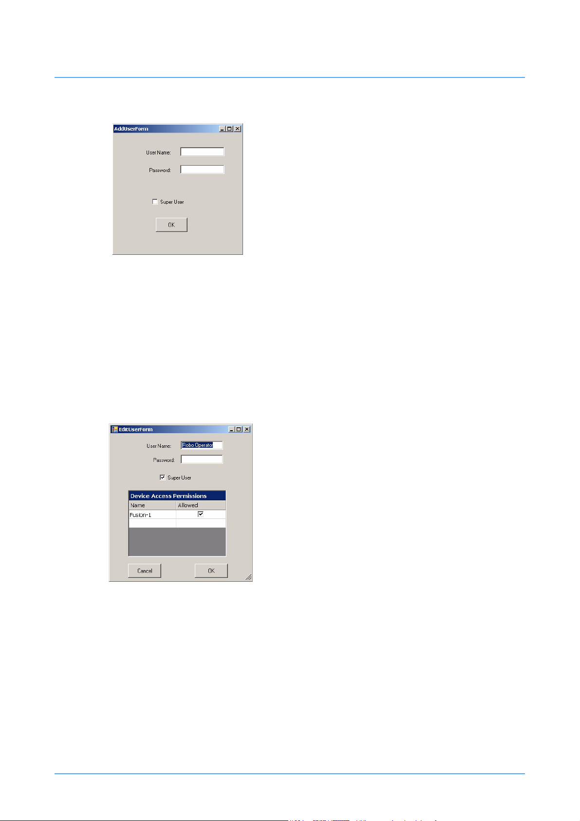
1.Select ADD USER on the Fusion User Editor dialog. The
AddUserForm dialog appears (Figure 6).
2. Enter the name of the user in the User Name field and then
enter the password in the Password field.
3. It is preferable to create all users as Super Users by selecting the Super User option. See Super User
on page 17 for information on Super User accounts.
16 VRC System Operators Guide
4. Click OK to create the user account.
Figure 6 AddUserForm dialog
Figure 7 EditUserForm dialog
Super User
All users have access to load any shows that have been
created by any other user. The Super User option on the
AddUserForm dialog defines whether or not any changes
to shots will be saved in the show file on the hard drive
or if the changes will be lost the next time the show is
loaded.
If the Super User option is selected, any changes to shots
made by this user and that are resaved will automatically
be saved to the show file on the hard drive.
If Super User option is not selected, and this user is the creator of the current show, any changes to
shots that are resaved will automatically be saved to the show file on the hard drive. The creator of
a show is considered a Super User of his or her own shows. If the option is not selected, and this
user is not the creator of the current show, any changes to shots that are resaved will not be saved
to the show file on the hard drive.
Editing a user account
1.On the Fusion User Editor dialog, select the user account
that you want to modify and then select EDIT.
2. The EditUserForm appears (Figure 7).
3. You can modify any of the account details. The Device
Access Permissions section lists the devices that are
available to the user and these can be selected or
deselected as required.
4. Click OK to save the changes to the user account.
Deleting a user account
1.On the Fusion User Editor dialog, select the user account
that you want to delete and then select DELETE.
Publication Part No. V4009-4980 Issue 3.1 17

Calibrating the touch-screen
All VRC system monitors are touch-screen enabled, allowing on-screen options to be selected by
touching the relevant graphic with a finger. It is also possible to select on-screen options using the
left mouse button. The touch-screen user interface closely resembles the Radamec TCPi system, and
can control multiple camera units.
The location that you touch and the “button” on the screen are physically separated by the thickness
of the touch screen glass. Therefore, depending on how you sit and your angle of view, the touch
screen may need recalibration. If you find that the on-screen pointer no longer matches the position
of your finger on the screen you should recalibrate.
Sit in a natural position that you will normally adopt whilst operating the touch-screen monitor.
Double click on Monitor Control Panel icon on the desktop and follow the on screen prompts.
NOTE: Refer to the User documentation supplied with the touch-screen for
information on regular maintenance, cleaning and setup instructions.
18 VRC System Operators Guide

VRC control panel
The VRC control panels are designed to integrate with the Vinten Radamec Control System,
providing control of robotic heads and pedestals. The control panel can be supplied with one or two
joysticks. The right hand joystick (Pan/Tilt/Zoom) controls the pan and tilt movements of the robotic
head and the zoom functions on the camera lens. The left hand joystick (XY/Height) controls the
steering, travel and height of the robotic pedestals. A separate rotary knob provides focus control for
the camera lens and the Fade Time bar adjusts the timing of the transition between stored shots.
Single joystick control panel
Single joystick control panels are designed to control robotic heads only and are supplied with a
single Pan/Tilt/Zoom joystick. There are options to control 8 or 16 camera units with or without
camera iris or black CCU functions, depending on the installed control panel model.
Dual joystick control panel
Dual joystick control panels are designed to control both robotic heads and pedestals and are supplied
with an XY/Height joystick on the left hand side of the control panel and a Pan/Tilt/Zoom joystick
on the right hand side. There are options to control 8 or 16 camera units with or without camera iris
or black CCU functions, depending on the installed control panel model. In addition to control of
Fusion and SP2000 robotic products, there is also an option to support the functionality of the RP2A
pedestal.
This guide details the use of all control panel variations, and therefore some functions may not be
present on the control panel installed. If a button or control described in the text or illustrations is
not present on your control panel, then your purchased model doesn’t support that function. It is also
possible that the installation engineer may customise the functionality of the system function buttons
affecting functions available and the precise location in the row.
Operating the control panel
Switching on the panel
When power is initially connected to the control panel, all push buttons will sequentially illuminate and
then extinguish after a period of approximately 3 seconds.
Configuring the operation of the control panel
The default mode of control panel functions and the sense of joystick controls is set in the Configuration
screen (see Configuring the VRC system on page 55).
Locking the control panel
The Panel Disable button locks all other controls on the panel to prevent accidental operation.
Publication Part No. V4009-4980 Issue 3.1 19

Remotely operating a Camera
Pan/Tilt/Zoom
On Air (Tally)
Camera Select Buttons 1-
16
Fade
StopFade TimeFocus
XY/Height
CCU Black Level
(option)
CCU Iris
(option)
Wash/Wipe (option)
Bumper Disable
Pan Follow Backup Link
X4
Panel Disable
Joystick Enable
Target Disable
Cut
Override
Infrared Disable
Camera preview
The Camera Select buttons (1-16) allow selection of individual camera units (camera, pan and tilt head
and pedestal - where fitted). Once selected, the depressed push button will illuminate and the camera unit
can be controlled by the joysticks. If the optional video switcher and preview monitor are installed, the
video from the relevant camera will be displayed on the video monitor.
Figure 8 VRC control panel
20 VRC System Operators Guide
NOTE: The on air (tally) indicators show which camera unit’s video
signal is currently live on air.
The illuminated camera select button indicates which camera
unit is being controlled from the panel.
If a selected camera unit is not available (because it is in Manual
mode for example), the camera select button will not remain
illuminated.

Pan/Tilt/Zoom joystick
By default, moving the joystick left and right will pan the camera left and right, moving the joystick
forward and back will tilt the camera down and up. Rotating the joystick clockwise will zoom out the
camera lens, and rotating it counter-clockwise will zoom in. If required, the direction of camera and zoom
movement relative to joystick movement can be customized in the Configuration Screen (see Configuring
the VRC system on page 55).
Focus control
Rotating this knob adjusts the camera lens focus.
Black level and iris CCU controls
CCU black level and iris functions are controlled by rotary knobs on the left hand side of the control panel.
Cut, Fade and Stop buttons
These buttons duplicate those on the touch-screen display.
NOTE: Ensure that the Panel Disable or Backup Link buttons on the
control panel are NOT illuminated before attempting to use the
Cut, Fade or Stop functions.
Cut
After a shot is selected on the touch screen you can cut from the current position to the selected shot.
Using Cut, the stored time in the shot is ignored and the transition is as fast as possible.
Fade
After a shot is selected on the touch screen you can fade from the current position to the selected
shot. Using Fade the duration of the transition is set by the stored time in the shot. However, if the
shot cannot be reached within the stored time, the transition is as fast as possible. In addition, the
fade time can be modified in real-time using the Fade Time bar (see Fade Time control on page 22).
Stop
Any time that a head or pedestal is moving during a Fade or Cut to a stored shot, the robotic
movement can be halted using the Stop button. Typically the Stop button would be used when there
is a risk of damage to the equipment or injury to personnel if the robotic movement were allowed
to continue.
There are two stopping options that are configurable in the Configuration screen. The first Stop
option provides a ‘gentle’ synchronised stop, stopping the pedestal in approximately two seconds
and is recommended for on-air use. The other stop option provides a ‘fast’ abrupt stop that is not
Publication Part No. V4009-4980 Issue 3.1 21

synchronised and may produce a small amount of instability on the pedestal and therefore should
not be used on-air. See Panel Options - Always stop fast on page 58.
When a shot is selected on the touch screen the Cut and Fade buttons will illuminate, indicating th at
these functions are available for selection. Once a cut or fade command is activated, either from the
touch-screen or the control panel, both buttons will extinguish on the control panel. The Stop button
will then illuminate, indicating that this function is available to halt robotic movement. When the
camera unit arrives on-shot or when the stop is selected, the Stop button will extinguish.
After using Stop to halt a robotic transition, you can complete the move by selecting the required
shot on the touch-screen and selecting Fade or Cut.
Fade Time control
The Fade Time bar affects the fade time between shots in real-time. When fading to a shot, pushing the
bar forwards will increase the fade time (slowing down the movement). Conversely, pulling the bar
backwards will decrease the fade time (speeding up the movement).
Wash wipe
The Wash Wipe button activates the wash wipe on the selected externally mounted environmental camera
unit.
X4
During normal mode of operation, the X4 button is off so that the speed of the pan and tilt movements are
proportional to the zoom angle of the camera lens. Pan and tilt move slowly when you are zoomed in and
quickly when you are zoomed out. When X4 is on, the pan and tilt movements are more sensitive when
zoomed in.
Remotely operating a Pedestal
The following functions are used to remotely operate a robotic pedestal. There are additional
functions on the control panel that are used only when operating an RP2A pedestal (see R2PA
control functions on page 23).
Joystick enable
The Joystick Enable button must be on and illuminated before you can move the pedestal around the studio
floor (in X and Y axes) using the XY/Height joystick. When the Joystick Enable button is off, the XY/
Height joystick only allows robotic height movement. This prevents accidental pedestal travel while
rotating the joystick to adjust camera height.
22 VRC System Operators Guide

XY/Height joystick
The XY/Height joystick is on the left hand side of the control panel and is used to operate a pedestal. By
default, moving the joystick left and right will cause the pedestal to travel west and east relative to the
target. Moving the joystick forward and back will cause the pedestal to move north and south. North is
the direction away from the side of the pedestal that has the cable connection panel (see Pedestal
orientation on page 34).
Rotating the joystick clockwise will lower the camera and rotating it counter-clockwise will raise the
camera. If required, the direction of camera movement relative to joystick movement can be customized
in the Configuration Screen (see Configuring the VRC system on page 55).
NOTE: Before the pedestal can travel across the studio floor, the
Joystick Enable button must be depressed and illuminated (see
Joystick Enable on page 22.
Pan follow
When Pan Follow is off, pushing the XY/Height joystick forwards and backwards on the ‘Y’ axis causes
the pedestal to travel north and south as defined by the target placement. north is the direction away from
the side of the pedestal with the cable connections (see Pedestal orientation on page 34).
When Pan Follow mode is on, pushing the XY/Height joystick forwards and backwards on the ‘Y’ axis
causes the pedestal to travel forwards and backwards in the direction that the camera is pointing.
Bumper disable
The Bumper Disable button turns off the pedestal bumper protection which arrests the SP-2000 and RP2A
pedestal travel on contact with an obstacle.
WARNING!
Risk of personal injury or damage to equipment when the Bumper
Disable button is depressed. The Override function will have no effect
on collision with an obstacle.
RP2A control functions
The following functions are only applicable when operating the RP2A pedestal. These functions are
additional to the other pedestal functions listed above.
Target disable
The Target Disable button prevents the RP2A pedestal from using the optical studio targets. The
selected pedestal will continue to use the dead reckoning positional system alone.
Publication Part No. V4009-4980 Issue 3.1 23

Backup link
The Backup Link button gives priority control to the control panel in the unlikely event of the VRC
system failing. This allows the robotic camera units to remain in operation.
Infrared disable
Where fitted, the infrared disable button turns off the selected Radamec RP2A pedestal infrared
proximity protection (which arrests pedestal travel before contact with an obstacle).
WARNING!
Risk of personal injury or damage to equipment when the Bumper
Disable button is depressed. The Override function will have no effect
on the RP2A pedestal proximity detection.
NOTE: If ALWAYS DISBLE IR is selected in the Configuration Screen
(see Always disable IR on page 69), the control panel will have
the INFRARED DISABLE function activated by default.
24 VRC System Operators Guide

Workspace
VRC System User Interface
Figure 9 Workspace
The VRC user interface is a Windows-based program that uses a conventional application window,
consisting of a title bar, a set of menus and buttons, and an editing pane comprising a grid of frames
used for creating shots and editing shows. The VRC user interface window works similar to other
application windows, allowing you to reposition the window on your computer desktop by dragging
it with your mouse (left button), minimise it (so that it appears only as an item on your task bar) and
maximise it (so that it appears full screen) and close the application using the Close button.
The title bar displays the current user logon name (e.g. Robo Operator) and the name of the current
show if one has been loaded.
Every time a shot is stored, a thumbnail image is captured from the camera and saved into an editing
pane (a grid of grey rectangles). These thumbnails allow you to quickly identify the shots without
requiring long descriptive names. Depending on the number of shots per show and the grid size
selected, the shots may span several pages. The grid size, number of shots that are visible on a single
Publication Part No. V4009-4980 Issue 3.1 25

page can be adjusted using the Grid Size option on the Configuration Screen (see Configuring the
VRC system on page 55). After shots are stored they can be moved, edited or deleted using the Edit
menu (see Edit menu on page 46). Shots can be created, stored and recalled as part of show files.
The robotic pedestals and heads can be selected and controlled from the workspace and the control
panel. Only camera buttons that are coloured white, green or blue are available to be controlled from
the touch-screen (see Camera Selection and Status bar on page 26).
Camera Selection and Status bar
Immediately below the editing pane is the Camera Selection and Status bar that displays the available
cameras. Once selected, the camera can be controlled using the control panel.
Figure 10 Camera Selection and Status bar
The colour of the camera button indicates the current status of the camera. These colours are
described in Table 1.
Table 1: Camera status
Green Camera currently selected and controlled by the control panel.
White Camera available for immediate selection and control.
Black Camera is offline and unavailable.
Blue Camera is currently under the control of another networked control panel.
Depending on your user account privileges, you may be able to ‘take rudely’ any
camera in the system (see Camera Control - always take rudely on page 60). If
you have permission to ‘take rudely’, selecting the camera will display a dialogue
box stating that the ‘device is being used by another operator, continue?’ Selecting
yes will transfer control of the camera to your control panel.
Brown Pedestal is in Local/Manual mode. Change the pedestal mode to Auto (robotic)
mode. The camera status will change to white when the pedestal is in Auto mode.
You must then enable the camera by selecting OPTS>ENBALE.
Grey Head is in Local/Manual mode. See Opts menu on page 33 for information to bring
a camera online.
26 VRC System Operators Guide

Functions and menus
Figure 11 menu dialog
At the base of the workspace is a selection of menu and function buttons that enable operators to
create and manage shows including editing shots, target and stop pedestals and configure the VRC
system.
Menu
Clicking on Menu will display the following dialog:
Show Management
See Show management on page 38 for details on the Show
Management functions.
Configuration
See Configuring the VRC system on page 55 for details on
Configuration functions.
Clear show
Clear Show will PERMANENTLY DELETE all shots from
the current show. There is no undo function. It is
recommended that you backup the show database
periodically to an external storage device such as a USB
flash drive.
Exit
Selecting Exit will close the VRC User Interface.
Edit
See Edit menu on page 46 for information on the Edit menu functions.
Publication Part No. V4009-4980 Issue 3.1 27

Stop
Any time that a head or pedestal is moving during a Fade or Cut to a stored shot, the
robotic movement can be halted using the Stop button. Typically the Stop button
would be used when there is a risk of damage to the equipment or injury to personnel
if the robotic movement were allowed to continue.
There are two stopping options that are configurable in the Configuration screen. The first Stop
option provides a ‘gentle’ synchronised stop, stopping the pedestal in approximately two seconds and
is recommended for on-air use. The other stop option provides a ‘fast’ abrupt stop that is not
synchronised and may produce a small amount of instability on the pedestal and therefore should not
be used on-air. See Panel Options - Always stop fast on page 58.
When a shot is selected on the touch screen the Cut and Fade buttons will illuminate, indicating that
these functions are available for selection. When a cut or fade command is activated, either from the
touch-screen or the control panel, both buttons will extinguish on the control panel. The Stop button
will then illuminate on the control panel, indicating that this function is available to halt robotic
movement. When the camera unit arrives on-shot or when the stop is selected, the Stop button will
extinguish.
After using Stop to halt a robotic transition, you can complete the move by selecting the required shot
on the touch-screen and selecting Fade or Cut.
Cut
After a shot is selected on the touch-screen you can cut from the current position to
the selected shot. With Cut the stored time in the shot is ignored and the transition is
as fast as possible.
Latched Cut
Use Latched Cut if you want to immediately cut to a shot when you select it on the touch- screen.
In the normal Cut mode you cue the shot by selecting it on the touch-screen and then initiate the
move by selecting Cut.
1. Make sure that no shots are currently cued (no shot thumbnails have a green
background).
2. Select Cut on the touch-screen - the button turns red to denote Latched Cut mode.
3. Check that the operating area around the cameras is clear.
4. Select a shot on the touch-screen. The thumbnail immediately turns red and the camera
moves to the selected shot.
5. Select other shots as required. In each case the thumbnail immediately turns red and the
camera moves to the selected shot.
6. Select Cut on the touch-screen to return to the normal Fade mode.
28 VRC System Operators Guide

Fade
After a shot is selected on the touch-screen you can fade from the current position to
the selected shot. Using Fade, the duration of the transition is set by the stored time in
the shot. However, if the shot cannot be reached within the stored time, the transition
is as fast as possible. In addition, the fade time can be modified in real-time using the
Fade Time bar on the control panel (see Fade time control on page 46).
Latched Fade
Use Latched Fade if you want to immediately fade to a shot when you select it on the touch- screen.
In the normal Fade mode you cue the shot by selecting it on the touch screen and then initiate the
move by selecting Fade.
1. Make sure that no shots are currently cued (no shot thumbnails have a green
background).
2. Select FADE on the touch-screen - the button turns red to denote Latched Fade mode.
3. Check that the operating area around the cameras is clear.
4. Select a shot on the touch-screen. The thumbnail immediately turns red and the camera
moves to the selected shot.
5. Select other shots as required. In each case the thumbnail immediately turns red and the
camera moves to the selected shot.
6. Select Fade on the touch-screen to return to the normal Fade mode.
Fade or Cut multiple shots
If you select shots on more than one camera and then select Fade or Cut, all of the cameras will start
moving at the same time. Before initiating a multi-camera move make sure that the area around all
of the relevant cameras is clear and that the cameras will not collide with each other.
Store
When a camera is positioned as required, the shot position can be saved in a show for
later use (see Adding shots to a show on page 41).
Publication Part No. V4009-4980 Issue 3.1 29

Virtual stick
Virtual Stick provides a convenient method of manually controlling the pedestal and/
or head from the touch-screen when a control panel is not available. Selecting Virtual
Stick will launch the Virtual Joystick window (Figure 12).
Figure 12 Virtual Joystick window
For any axis, use the touch-screen (or click and hold the left mouse button) to drag the Virtual
Joystick in the required direction. Removing your finger from the touch-screen (or releasing the
mouse button) stops the movement. The direction that you drag for X, Y, Pan and Tilt corresponds
to the direction of movement. The distance that you drag for X, Y, Pan, Tilt, Height and Zoom
corresponds to the speed of movement.
Sequence of shots
A series of shots can be saved as a sequence, similar to a slide show, and then replayed
during the show. The shots are played in the order they were saved in the sequence.
The sequence can be created from any existing shots for a particular camera. Shots
from other cameras cannot be added to the sequence.
Select Sequence and then click on an empty thumbnail (grey) in the editing pane on the workspace.
The Sequence window appears (Figure 13) containing an editing pane similar to that on the
30 VRC System Operators Guide

workspace. Options provided allow you to play the sequence, edit the time of the shot and delete shots
from the sequence.
Figure 13 Sequence window
A sequence of shots is created by dragging the required shots from the editing pane on the workspace
into the editing pane in the Sequence window. It is preferable to place the shots into the editing pane
in the required order because shots cannot be rearranged once inserted. When you have inserted all
of the shots, you can run through the sequence by selecting the PLAY option.
CAUTION! Ensure that the area is clear of persons or potential hazards before
you select the Play option. The Play option will physically move the
camera, pedestal and head, following the predefined movements
(shots) in the sequence.
When the sequence is complete, select EXIT to save the sequence and return to the workspace. When
a sequence has been created, ‘Seq’ appears in the top right corner of the thumbnail. When the
sequence is playing, the thumbnail is coloured purple. The sequence can be edited using the options
from the EDIT Menu (see Edit menu on page 46).
A sequence can be used anywhere within the show. When one sequence follows another in the show,
it is important that you do not start the next sequence prior to completing the first sequence. If you
do want to start the next sequence before the first sequence has finished, you must stop the first
sequence using the STOP button before starting the next sequence.
Deleting a Shot from the sequence
To delete a shot from the sequence, select the shot and then select DELETE. The shot is deleted
from the sequence but is not deleted from the editing pane on the workspace.
Publication Part No. V4009-4980 Issue 3.1 31

Editing the shot time
Figure 14 Edit time dialog
The time of the shot within the sequence can be edited by
selecting the shot and then selecting EDIT TIME. The
New Sequence Shot... dialog appears (Figure 14).
Enter the new time for the shot using the keypad and then
select ENTER.
Selecting DELETE will delete the last digit entered.
Select ENTER to save the new shot time and return to the
Sequence window.
When the time of a shot is edited, the total time of the
sequence, displayed in the Sequence window changes.
Focus
When on Shot (thumbnail coloured dark blue), selecting FOCUS lets you adjust the
camera lens focal point (position). The lens will zoom to full focal length onto the
subject, allowing you to adjust the focus using the Focus knob on the control panel
and adjust the pan and tilt settings.
The Focus menu provides options to save the new focus position (KEEP SHOT) or return to the
original saved lens position (KEEP CAMERA).
Keep Shot
When the focus has been adjusted, selecting KEEP SHOT will save the camera lens focus position
whilst returning the camera to its original shot position, with the original pan and tilt settings.
Keep Camera
When the focus has been adjusted, selecting KEEP CAMERA will return the camera to its original
position, with the original pan and tilt settings and original lens focus position. The adjusted focus
setting will not be saved.
Page up/Page down
The shots in a show can be positioned on multiple pages depending on
the grid size. Use the Page up and Page down buttons to scroll through
the pages.
32 VRC System Operators Guide

Opts menu
Target
See Targeting the pedestals on page 34 for information on using this function to
target the pedestals.
Return
Select RETURN in the OPTS menu to go back to the workspace without performing either an
Enable or Target command.
Enable a camera
If a camera is offline (black camera select button) then it is likely that there is a problem with the
camera or system setup. Check that the camera is powered on and that all cabling to the camera is
connected correctly. If the camera does not come online, further investigations are necessary.
If the head is in manual mode (grey camera select button) it must be enabled from the controller
before the camera can be controlled. Make sure that the head is powered On. The head will
automatically switch to Robotic (auto) mode if necessary. Select the camera on the touch-screen or
control panel and then select OPTS>ENABLE to bring the camera online.
If the pedestal is in manual mode (brown camera select button) it must be switched to Robotic (auto)
mode and then enabled from the controller before it can be controlled. Make sure that the pedestal
is powered On and switched to Robotic mode, then select the camera on the touch-screen or control
panel and then select OPTS>ENABLE to bring the camera online.
NOTE: The camera must be re-targeted after enabling, when switching the
pedestal from manual to automatic mode. See Targeting a pedestal
on page 34. A head mounted on a pedestal can be placed into
manual mode without the need for re-targeting.
Publication Part No. V4009-4980 Issue 3.1 33

Targeting the pedestals
South side
East side
West side
North side
Before shots can be created and stored, all robotic pedestal movements must reference a target. The
target for each pedestal is either permanently adhered to the studio floor (Fusion and SP-2000
pedestals) or mounted at the edge of the studio as a vertical bar-code (RP2A pedestals). Studio
configurations without pedestals do not need to reference a target.
Fusion pedestal
Pedestal orientation
For simplicity, the sides of the pedestal are often referred to as North, South, East or West as shown
in Figure 15.
Figure 15 FP-145 pedestal orientation
Targeting the pedestal
1. Select the camera to be targeted on the touch-screen or the control panel.
2. Use the XY/Height joystick on the control panel to position the pedestal so that its north side (with
the Emergency Stop switches) is over the edge of the target as shown in Figure 16.
34 VRC System Operators Guide

Figure 16 Fusion Pedestal targeting start positions
FP-145 MKI pedestal
3 line floor target
FP-145 MKII pedestal
L shaped floor target
3. If the edge of the pedestal and the edge of the target are not parallel, switch the pedestal from Auto
to Manual and from Crab to Steer, rotate the pedestal to align it with the target. Switch from Steer
to Crab and switch from Manual to Automatic mode. Enable the pedestal (OPTS>ENABLE).
4. Select OPTS>TARGET.
5. The select the relevant target from the list and select OK. The Fusion FP-145 pedestal will drive
itself across the target while optically scanning the floor to determine the datum target position.
When the pedestal stops moving, a dialog appears confirming that targeting was completed
successfully.
NOTE: Make sure that the pedestal stops in the position shown in Figure 17
when it finishes targeting. This ensures that the target sensor (located
approximately below the handle on the East side of the pedestal)
travels completely across the target. If the pedestal stops before the
sensor crosses all lines (even if the pop-up window indicates targeting
was successful) repeat steps 1 through 5. If the pedestal travels
beyond the edge of the target you will get an error message and you
must repeat steps 1 through 5.
Publication Part No. V4009-4980 Issue 3.1 35

Figure 17 Fusion Pedestal correct position after targeting
FP-145 MKI pedestal
3 line floor target
FP-145 MKII pedestal
L shaped floor target
SP-2000 pedestal
1. Select the camera to be targeted on the touch-screen or the control panel.
2. Use the XY/Height joystick on the control panel to position the pedestal so that it is positioned over
the target as shown in Figure 18.
3. Select OPTS>TARGET.
4. Select the relevant target from the list and select OK. The SP-2000 pedestal will reposition and align
itself to the target. When the pedestal stops moving a popup window will confirm that targeting was
completed successful.
36 VRC System Operators Guide

Figure 18 SP-2000 pedestal targeting start position
RP2A pedestal
RP2A pedestals will automatically reference their target - manual targeting is not required.
Publication Part No. V4009-4980 Issue 3.1 37

Shots and shows
This section covers the creation, editing and deleting of shots and show files.
Show management
A show is a collection of stored shots from multiple camera systems saved in one file. To store shots
in the grid display, either a new show must be created or an existing show must be loaded.
• Select MENU>SHOW MANAGEMENT to access Show Management functions. The Show
Management dialog appears (Figure 19).
Figure 19 Show Management dialog
Creating a new show
To create a new show:
1. Select MENU>SHOW MANAGEMENT>NEW SHOW.
2. Use either the keyboard or the touch-screen keyboard to enter a name for the new show.
3. Select ENTER to return to the workspace which is ready to store shots in this new show.
The new show name is displayed in the title bar of the workspace.
Loading a show
To load an existing show:
1. Select MENU>SHOW MANAGEMENT>LOAD SHOW.
2. Select the desired show from the scroll list.
38 VRC System Operators Guide

3. Select OK to return to the workspace showing the first page of shots in the loaded show. Select
CANCEL to return to the workspace without loading a show.
The name of the loaded show appears in the title bar of the workspace.
List all shows
To view a list of all stored shows:
1. Select MENU>SHOW MANAGEMENT>LIST SHOWS.
2. View the stored shows on the scroll list.
3. Select CANCEL and OK to return to the workspace.
Deleting a show
NOTE: There is no undo option following a show deletion. A deleted show
CANNOT BE RESTORED. It is recommended that you backup the
show database periodically to an external storage device such as a
USB flash drive as described below.
To delete a show:
1. Select MENU>SHOW MANAGEMENT>DELETE SHOW.
2. Select the desired show from the scroll list.
3. Select OK to delete the show or select CANCEL to return to the workspace without deleting a show.
Creating the home or target shot
Before creating shots for your new show (named “morning” in the following examples) you should
create a shot called HOME or TARGET for each pedestal. The HOME or TARGET shots position
each pedestal at the correct location for targeting. At the end of every show it is good practice to send
each pedestal to its HOME or TARGET shot. Then, before the next show, you can quickly target each
pedestal to ensure that all of the shots for the next show will be exactly as they were stored.
1. Select MENU>CONFIGURATION and make sure that Require Shot Name is On and Require Shot
Time is Off (to use the default shot time). Select RETURN.
2. Select a pedestal on the touch screen or the joystick panel.
3. Use the joysticks to move the pedestal to the correct starting position for targeting (see Targeting
the pedestals on page 34).
4. Select STORE on the touch screen and select a position on the grid to store the shot.
Publication Part No. V4009-4980 Issue 3.1 39

5. Type in a name (e.g. HOME) and select >ENTER.
NOTE: The shot name can be a maximum of 16 characters long.
6. The shot will be saved with the default fade time (e.g. 4 seconds).
NOTE: The fade time specifies the number of seconds that the robotic system
will take to move the camera from its current position to the selected
shot position when FADE is selected on the touch-screen or the
control panel.
The default fade time is set in the Configuration Screen. Or you can
manually enter a fade time for each shot as it is saved (see Camera
control on page 60).
The stored fade time can always be modified on-air using the Fade
Time bar on the control panel.
The maximum fade time is 120 seconds.
7. Repeat steps 2 through 6 for the remaining pedestals in the system.
NOTE: Every time that you store a shot, the show file on the hard drive is
automatically saved.
For SP-2000 pedestals, the TARGET or HOME shot is centered over the target. Therefore, the
pedestal will protect the target from any damage which may be caused by people walking on them,
scenery being moved over them, floor cleaning and so on. For Fusion pedestals, since the TARGET
or HOME shot is located behind the target and does not offer the same protection. You may want to
create an additional shot called OVER TARGET to protect the target from damage between shows.
The workspace should now have one target or home shot for each pedestal. In Figure 20 the show
called “morning” has HOME shots saved for Fusion pedestals 1, 2 and 3. This show is now ready to
have additional shots created and stored.
40 VRC System Operators Guide

Figure 20 Workspace displaying HOME shots
Adding shots to a show
In this section you will create the first few shots for your new morning show. Let’s assume that the
shots are:
• Camera #1 - A wide shot of the news set to open the show - called OPEN
• Camera #1 - A tight shot on anchor Fred - called FRED TIGHT
• Camera #1 - An over the shoulder key shot on anchor Fred - called FRED KEY
• Camera #2 - A 2-shot of the anchors - called 2SHOT
• Camera #2 - A tight shot on the anchor - called ANCHOR TIGHT
• Camera #3 - A tight shot on anchor Liz - called LIZ TIGHT
• Camera #3 - An over the shoulder key shot on anchor Liz - called LIZ KEY
Publication Part No. V4009-4980 Issue 3.1 41

To add shots:
1. Make sure that the morning show with its target (home) shots is loaded.
2. Select MENU>CONFIGURATION and make sure that Require Shot Name is On and Require Shot
Time is Off. Select RETURN.
3. Select camera #1 on the touch-screen or the control panel.
NOTE: The video signal for the selected camera can be viewed on the
preview monitor.
4. Use the joysticks to move the camera into position for the first shot, and then frame and focus the
shot.
5. Select STORE on the touch-screen and select a position on the editing pane to store the shot.
6. Type in a name (e.g. OPEN) and select >ENTER.
7. The shot will be saved with the default fade time and its thumbnail displayed on the editing pane.
8. Repeat steps 4 through 7 for the remaining shots on camera #1.
9. Select camera #2 on the touch screen or the control panel and repeat steps 4 through 7 for the
required shots on camera #2.
10. Select camera #3 on the touch screen or the control panel and repeat steps 4 thro ugh 7 for the
required shots on camera #3.
After adding these shots your workspace will look something like that shown in Figure 21.
42 VRC System Operators Guide

Figure 21 Morning show with Shots added
Publication Part No. V4009-4980 Issue 3.1 43

Shot status colour codes
Shots stored on the grid display are colour coded to indicate the shot status (Figure 22).
Figure 22 Shot status colour codes
Table 2: Shot status colours
Frame Colour Description
Red background Indicates that the camera is moving (via Cut or Fade) to the shot. See Fusion-1
target shot in Figure 22.
Yellow banner across the frame
corner
Green background Indicates that this shot is cued and the camera will move to this shot when you
Dark blue background Indicates that the camera is ‘exactly’ on shot as stored in the show file. See
Purple background Indicates that this is a Sequence currently selected for play.
Light blue background Indicates that the camera has been trimmed off shot away from the shot stored in
Indicates that this is the last shot selected. See Fusion-1 target shot in Figure 22.
select Cut or Fade. See Fusion-4/44 shot in Figure 22.
Fusion-3/3WX STAND END shot in Figure 22.
the show file. See Fusion-2/2K shot in Figure 22.
44 VRC System Operators Guide

Table 2: Shot status colours
Frame Colour Description
Grey background Indicates shots that are available for selection.
Using shots
In this section you will explore using shots to become familiar with normal on-air operations, using
the morning show sample shots that were created earlier Figure 23.
Figure 23 Using shots
Fade
1. Select a shot on camera #1 and its thumbnail will turn green.
2. Select FADE on the touch screen or the joystick control panel, the thumbnail turns red and the
camera starts its timed transition (the time saved in the shot) from its current position to the stored
shot.
3. During the move the fade timer in the shot thumbnail indicates the progress.
Publication Part No. V4009-4980 Issue 3.1 45

4. When the camera reaches the stored shot the thumbnail turns from red to dark blue.
NOTE: If the selected shot cannot be reached within the time stored in the
shot, the camera will move at its maximum speed.
Cut
1. Select a shot on camera #2 and its thumbnail will turn green.
2. Select CUT on the touch screen or the control panel, the thumbnail turns red and the camera moves
at maximum speed from its current position to the stored shot.
3. During the move the fade timer in the shot thumbnail indicates the progress.
4. When the camera reaches the stored shot the thumbnail turns from red to dark blue.
Stopping A Fade Or Cut
You can prevent a camera from bumping into an obstacle using the STOP button. Or, if a camera is
partway through a slow fade to a shot that you no longer want to use, the STOP button will halt the
movement so that you can select a different shot. You can select either a profiled (smooth) Stop that
is acceptable for on-air use or an abrupt Stop that generally would not be used on-air (see Panel
options - Always stop fast on page 58).
1. Make sure that the red thumbnail is the camera that you want to stop.
2. Select STOP on the touch-screen or the joystick control panel to stop the movement of the pedestal
and/or head. The selected shot will change from red to grey.
3. Now you can select a the same shot or a different shot and FADE or CUT to it.
Fade Timer Control
The fade time can be quickly modified using the Fade Time bar on the control panel.
1. Select a shot on camera #1 and its thumbnail will turn green.
2. Select FADE on the touch-screen or the control panel and immediately pull the Fade Time bar
towards you to decrease the fade time and speed up the movement.
3. The fade timer in the shot thumbnail will indicate the progress towards the new time for the shot.
4. Push the Fade Time bar away from you to increase the fade time and slow down the movement.
Edit menu
The Edit menu provides options that let you rename shots, modify the fade time, delete shots, resave
a shot or swap shot positions on the grid. The RETURN option can be used to cancel out of the Edit
menu, returning to the workspace and displaying the Camera Selection and Status bar.
46 VRC System Operators Guide

1. From the workspace select EDIT. Only the Latched Delete and Return buttons are available from
the Edit menu until you select a shot on the grid.
2. Select a shot on the grid to display the additional Latched Time, Name, Time, Delete, Resave and
Swap buttons as shown in Figure 24.
Figure 24 Edit menu
Latched delete
Use Latched Delete when you want to delete multiple shots. The normal Delete mode deletes a single
shot and then returns you to the workspace. Latched Delete keeps you in the Edit menu after each
deletion.
1. Select LATCHED DELETE.
2. Select a shot and confirm the deletion.
3. Select another shot and confirm the deletion.
4. Repeat until all of the desired shots have been deleted.
5. Select LATCHED DELETE to exit the mode and select RETURN to go back to the workspace.
Publication Part No. V4009-4980 Issue 3.1 47

Latched time
Use Latched Time when you want to modify the time of several shots. The normal Time mode
modifies a single shot and then returns you to the workspace. Latched Time keeps you in the Edit
menu after each shot is modified.
1. Select LATCHED TIME.
2. Select a shot and modify its time.
3. Select another shot and modify its time.
4. Repeat until all of the desired shots have been modified.
5. Select LATCHED TIME to exit the mode and select RETURN to go back to the workspace.
Name
To edit a shot name:
1. Select EDIT.
2. Select the desired shot from the grid display.
3. Select NAME.
4. Type in the desired shot name and select ENTER (on the touch-screen or the keyboard) to return to
the workspace.
NOTE: The shot name can be a maximum of 16 characters long.
Time
To modify the time of a shot:
1. Select EDIT
2. Select the desired shot from the grid display.
3. Select TIME.
4. Type in the desired shot time (in seconds) and select ENTER to return to the workspace.
Delete
To delete a single shot:
1. Select EDIT
2. Select the desired shot from the grid display.
3. Select DELETE and YES to delete the shot and return to the workspace.
48 VRC System Operators Guide

Resave
Resave allows you to save a new shot position in place of a previous saved shot in the editing pane.
1. Select EDIT.
2. Select the desired shot from the grid display.
3. Use the joystick on the control panel to reposition the camera as desired.
4. Select RESAVE save the newly positioned shot and return to the workspace.
Swap
Allows you to rearrange the position of the shots on the editing pane by exchanging pairs of shots or
exchanging a shot with an unused position.
1. Select EDIT.
2. Select the shot on the grid display that you want to move.
3. Select SWAP.
4. Select a second shot or an unused location to swap the shots on the editing pane and return to the
workspace.
Return
Select RETURN to go back to the workspace.
Publication Part No. V4009-4980 Issue 3.1 49

Putting it all together
In this section you will use many of the concepts and features covered in the preceding pages. The
hypothetical “morning” news is a 3 camera show with 2 anchors (LIZ and FRED), a weatherperson
MEGAN and a field reporter REBECCA. You will block a few more shots for the show and use them
as you follow the simplified rundown.
1. Make sure that the morning show is loaded. The workspace should look similar to Figure 25.
Figure 25 Initial shots for the Morning Show
2. If you do not have these shots created, see Adding shots to a show on page 41.
3. Select MENU>CONFIGURATION and make sure that Require Shot Name is On and Require Shot
Time is Off. Select RETURN.
50 VRC System Operators Guide

Blocking additional shots
1. Create the following additional shots that are called for in the rundown for the show:
• Camera #1 - A wide 3-shot of the anchors and the weather centre - called 3SHOT WX
• Camera #1 - A medium 3-shot of the anchors and the weather centre - called 3SHOT WX
END
• Camera #1 - A bumper for the end of the show that starts with a 3 shot of the anchor desk
- called END BUMP. The pedestal slowly moves away from the desk, increases height
and zooms wide - called END BUMP END. Set a fade time of 20 seconds for this shot.
• Camera #2 - An over the shoulder key shot - called ANCHOR KEY
• Camera #3 - A wide shot on the weatherperson standing at the weather centre - called
WX STAND
• Camera #3 - A medium shot on the weatherperson standing at the weather centre - called
WX STAND END
2. The workspace should now look similar to Figure 26.
3. The positioning of the shots on the grid is a matter of personal preference. You may choose an order
that matches how shots will be called for in the rundown for the show, or any arrangement that suits
your style of operation. Shots can be used in any order as stories are dropped or added, or as the
director requires any last minute modifications to the rundown for the show.
4. If the screen is full of shots, you may want to move the HOME shots to a lower page since they will
not normally be needed during the show.
Publication Part No. V4009-4980 Issue 3.1 51

Figure 26 Shots for the Morning Show
Air time philosophy
While airing a show you will be occupied with three primary tasks - cueing, trimming and tracking
shots.
Cueing
Cueing is the process of setting up the shots before they are used on-air. A shot is selected, the
thumbnail turns green, you FADE or CUT to it and the thumbnail turns dark blue when the camera is
“on shot”. It is important that you stay ahead of the rundown by cueing shots as early as possible. As
time permits (especially during remote feeds and commercial breaks) you can have 2 or 3 shots cued
ahead of the rundown.
Trimming
After a camera arrives “on shot” and before it is on air, you will want to take control at the joystick
panel and check framing and focus and trim the shot as needed. This lets you correct for a different
anchor than when the shot was created or when the talent is not on their mark. After trimming a shot
52 VRC System Operators Guide

its thumbnail will be light blue and you will usually replace it (select STORE and select the shot) and
the thumbnail will turn dark blue. This ensures that the shot will be correctly framed for the rest of
the current show.
Tracking
When a shot is on air you can track the talent if they shift in the frame, slide behind an over the
shoulder box etc. Select the on-air camera at the control panel and track the shot as needed.
Sample news show rundown
TALENT SLUG DIRECTOR
NOTES
ANIMATION OPEN 1-OPEN Select 3SHOT WX on Cam#1
FRED HEADLINE 1 2-2SHOT Select CUT on Cam#1
LIZ HEADLINE 2 2-2SHOT When Cam#1 is at 3SHOT WX (dark blue)
FRED WEATHER CHIT
CHAT
MEGAN STORMS STORMTRACKER
LIZ CONSTRUCTION 3-LIZ TIGHT Check Cam#3 framing, track if needed
1-PUSH 3-SHOT WX Select FADE on Cam#1
GRAPHICS
VRC OPERATOR ACTIONS
Select OPEN on Cam#1 and CUT to it
Select 2-SHOT on Cam#2 and CUT to it
Trim and RESAVE if needed
Select LIZ TIGHT on Cam#3 and CUT to it
Trim and RESAVE if needed
Check Cam#2 framing, track if needed
Trim and RESAVE if needed
Select 3SHOT WX END on Cam#1
Check Cam#1 framing, track if needed
Select ANCHOR KEY on Cam#2, CUT to it
Select FRED KEY on Cam#1, CUT to it
Trim and RESAVE if needed
Select LIZ KEY on Cam#3
LIZ PAN 3-LIZ KEY
GRAPHICS MAP
FRED BUDGET 1-FRED KEY
B ROLL INSERT
LIZ PARKING 2-LIZ KEY
LIVE REMOTE 2
REBECCA PARKING LIVE REMOTE 2 Select FRED TIGHT on Cam#1, CUT to it
Publication Part No. V4009-4980 Issue 3.1 53
Select FADE on Cam#3
Check Cam#3 framing, track if needed
Check Cam#1 framing, track if necessary
Select Cam#2, trim and RESAVE if needed
Check Cam#2 framing, track if needed
Select 2 SHOT on Cam#2, CUT to it
Select Cam#1, trim and RESAVE if needed
Select Cam#2, trim and RESAVE if needed

TALENT SLUG DIRECTOR
NOTES
VRC OPERATOR ACTIONS
FRED TRAFFIC 1-FRED TIGHT
TRAFFIC CAMS
LIZ/FRED CHIT CHAT
WEATHER TOSS
MEGAN QUICK WEATHER 3-PUSH WX STAND Select FADE on Cam#3
FRED GOODBYE 2-2SHOT When Cam#1 is at END BUMP (dark blue)
2-2SHOT Check Cam#2 framing, track if needed
1-BUMP Select FADE on Cam#1
Check Cam#1 framing, track if necessary
Select WX STAND on Cam#3, CUT to it
Select END BUMP on Cam#1, CUT to it
When Cam#3 is at WX STAND (dark blue)
Trim and RESAVE if needed
Select WX STAND END on Cam#3
Check Cam#3 framing, track if needed
Trim and RESAVE if needed
Select END BUMP END on Cam#1
54 VRC System Operators Guide

Configuring the VRC system
The Configuration Screen provides default settings for various operating parameters. On the User
Interface window select MENU>CONFIGURATION to display the Configuration Screen (Figure
27).
Figure 27 Configuration screen
After making the required changes on this screen select RETURN to go back to the workspace.
Grid display options
Grid size
The number of rows and columns of shots that can be seen on a single page in the editing pane is user
selectable. The minimum grid size is 2 rows by 3 columns per page. The maximum grid size is 8 rows
by 8 columns per page. A show can extend over multiple pages that are viewed by using the Page
Down/Up button in the lower right.
To set the grid size:
1. Select GRID SIZE and choose one of the rows x columns display options on the left h and side.
2. The preview panel to the right displays the layout you selected.
Publication Part No. V4009-4980 Issue 3.1 55

Figure 28 Grid Size selection dialog
The picture on the left is an example
of the workspace with the grid size
set to 7 x 8.
The picture on the right is an
example of the workspace with the
grid size set to 3 x 4.
3. Select OK to accept the new Grid Size or CANCEL return to the Configuration Screen without
making a change.
Reducing the number of rows and columns makes the shot thumbnails larger and easier to identify as
shown in the Figure 29, but if you choose to set the grid size for larger thumbnails you may have to
scroll through several pages of shots in a single show.
Figure 29 Grid size examples
56 VRC System Operators Guide

NOTE: If you select fewer columns in the grid after creating a show, the shots
in the higher columns (E, F, G, H in the example above) will be off the
screen to the right and cannot be viewed or selected. Shots in higher
numbered rows can always be viewed by using the page down/up
button.
Display headers
The column and row headers (ABC/123) can be turned on or off. The headers are useful when a show
extends over multiple pages.
Stick settings
These parameters select the sense of the controls on the control panel to suit the operator’s
preference. For example, pushing the Tilt joystick away from you can cause the head/camera to tilt
up or down. Or, you can choose clockwise on the Zoom knob to result in zoom in or zoom out. You
can select Normal (button is blue) or Reverse (button is black) for: Pan; Tilt; Zoom; Focus; Elevation.
Selecting the Stick Settings option displays a number of options that let you adjust the gain and
deadband settings (Figure 30).
Figure 30 Stick Preferences
Before changing the settings, you may need to change the profile. The profile for each setting (P/T
profile, Zoom profile, Focus profile and Z profile) can be set to either Compound, Linear or
Expediential.
Publication Part No. V4009-4980 Issue 3.1 57

Use the Up/Down arrows to adjust the gain and deadband settings. The gain is used to set the velocity
of the movement of the head, pedestal or camera lens, with the gain setting of 100 being the fastest
speed of movement. The deadband setting is used to adjust the amount of play that is often
experienced before the joystick starts to physically move the pedestal, head or camera lens. ;
NOTE: The pan and tilt settings are synchronised; any change to the pan gain
will equal the change to the tilt gain setting.
ALWAYS turn off X4 on the control panel before adjusting the Zoom
profile.
Panel options
These functions can be toggled On (the button is blue) or Off (the button is black). The selections are
stored for each User Name that has been created. These settings determine the state of the control
panel buttons after a User Name logs in.
Table 3: Panel option settings
Option ON OFF
Always enable pan Relative
Always enable drive The JOYSTICK ENABLE button on the con-
Double button push All control panel buttons must be pressed
Always stop fast
For a pedestal that is in
motion during a Cut or
Fade between shots,
this function defines the
behaviour if you select
STOP on the touchscreen or on the control
panel. In both modes the
position of the pedestal
is maintained so that
you can select a shot
and Fade or Cut to it
without needing to target
the pedestal.
The PAN FOLLOW button on the joystick
control panel is On after user login.
When selected the X-Y orientation relates to
the pan orientation.
trol panel will be On after user login.
twice to activate any function.
The pedestal will immediately stop moving.
This abrupt change of motion is not desirable for a camera that is on-air but does
ensure an immediate stop to avoid a collision
The PAN FOLLOW button on the joystick
control panel is Off after user login.
When not selected, the Pan Follow function
no longer operates and normal X-Y operation resumes.
The JOYSTICK ENABLE button on the control panel will be Off after user login.
Pressing a control panel button once will
activate the function.
The pedestal will decelerate and coast to a
stop. This smooth change of motion is
desirable if the camera is on-air. However,
to avoid a collision, you must take into
account the amount of pedestal travel after
selecting STOP.
58 VRC System Operators Guide

Panel options for pedestals
The following options only affect the operation of the RP2A pedestal.
WARNING!
Risk of personal injury or damage to equipment when these functions
are activated. Activating these functions will allow pedestals to be used
in close proximity.
Always override
If ALWAYS OVERRIDE is On, the OVERRIDE button on the joystick control panel will be On
after user login. The selected Radamec RP2A pedestal will continue moving at quarter speed after
detection of an infrared proximity warning or a collision with an obstacle (see Bumper disable on
page 23).
WARNING!
1. The ALWAYS OVERRIDE function will have no effect on
Radamec RP2A pedestal proximity detection, if the Infrared
Disable button on the control panel is On.
2. The ALWAYS OVERRIDE Radamec RP2A pedestal function will
have no effect on collision with an obstacle, if the Bumper
Disable button on the control panel is On.
Always disable IR
If ALWAYS DISBLE IR is On, the INFRARED DISABLE button on the joystick control panel will
be On after user login (see Infrared disable on page 24). The infrared proximity protection (which
stops pedestal movement before contact with an obstacle) is Off for all Radamec RP2A pedestals
in the system.
The following option affects the operation of the SP-2000 and RP2A pedestals:
Always disable bumpers
If ALWAYS DISABLE BUMPERS is On, the BUMPER DISABLE button on the control panel will
be On after user login (see Bumper disable on page 23). The bumper protection feature (which
stops pedestal movement after a collision with an obstacle) is Off for all Radamec RP2A pedestals
in the system.
Publication Part No. V4009-4980 Issue 3.1 59

Camera control
Table 4: Camera Control option settings
Option ON OFF
Deselect A camera that has been selected can be
deselected by touching it on the touch
screen.
Always take rudely Selecting a camera at one controller will
immediately take control away from a second controller that may have been using the
camera.
A camera can only be deselected by selecting a different camera.
A dialog appears requesting you to confirm
that you want to take control of the camera
from the other controller.
Shot options
Information that is required and displayed for each saved shot is user selectable.
Table 5: Shot option settings
Option ON OFF
Display Shot Name The name of each shot is superimposed on
the shot thumbnail.
Require Shot Name You will be prompted to type in a name
when you store a new shot. This is the most
common mode of operation.
The shot name is not displayed.
The system will automatically assign a
number to each saved shot. This can save
time but the shot names are no longer
descriptive.
Display shot time The time of each shot is superimposed on
the shot thumbnail.
Require shot time You will be prompted to enter a time when
you store a shot.
The time is not displayed.
The default shot time will be used for each
stored shot. This is the most common mode
of operation since it is faster than entering
times each time you store a new shot.
60 VRC System Operators Guide

Shot preferences
Table 6: Shot Preferences settings
Option ON OFF
Take Camera When you select a shot on the touch screen,
the Camera Preview selection on the joystick control panel automatically follows and
the joysticks will control the camera for the
selected shot.
Delete Warning Every time you delete or replace a shot a
warning dialog appears and requires you to
confirm the deletion or replacement.
Default time Requires you to enter a default time that will
be used when you store shots if the
REQUIRE SHOT TIME function is Off.
Allow deselect When you select a shot on the touch screen,
you can deselect that shot by touching it a
second time.
The shot selection on the touch screen and
the Camera Preview selection are decoupled. So, let’s say that camera #1 is on-air
and being trimmed with the joysticks. You
can select the next shot on camera #3 and
Fade or Cut to it while continuing to trim
camera #1 with the joysticks.
Shots will be deleted or replaced immediately. This mode should be used with caution because there is no undo feature to
restore a deleted shot.
When you select a shot on the touchscreen, you can only deselect that shot by
selecting a different shot on the same camera. Touching a selected shot a second time
has no effect.
Publication Part No. V4009-4980 Issue 3.1 61

Database Schedule Service
The VRC Database Schedule Service lets users specific database replication, restore, user-defined
database maintenance tasks in a fully automatic, scheduled way.
Configuring the Database Schedule Service
Standard installation will install the VRC DB Schedule Service in your windows OS. By default this
service will work on free distributed SQL Server Express 2005.
To manually launch the service, select Start>AllPrograms>vitec group camera dynamics ltd
>VRC Database Schedule Service and then select VRC Database Schedule Service UI.
Alternatively it can be launched automatically after the PC is booted by setting this in Services.
Figure 31 VRC DB Schedule Service Information
How to Schedule a Database Service
Starting the Database Service UI
After you have created the two databases (VrcsConfiguration and VrcsCore) using the Database
Creator, the first time you install the Fusion Control System you will be able to manage the database
directly using SQL Server Management Studio Express. You can use this program to automatically
schedule regular or one time database maintenance locally or remotely on another physical location.
This program will remain running in the background as a windows service.
1. Open the SQL Server Management Studio Express program. Check that the databases
VrcsConfiguration and VrcsCore have been successfully created.
62 VRC System Operators Guide

2. Double click the icon on system tray to start the VRC DB Schedule Service UI (Figure 32).
Figure 32 VRC DB Schedule Service UI
3. All three servers (SQL Server Browser, SQL Server Express and DB Schedule Service) should be
running as shown in Figure 32. If any of the servers need to be started, click the appropriate Start
button for the server in the Database Service UI window.
4. Click Configure Schedule Service to display the Scheduled DB Services window (Figure 33). This
window displays the service schedule list.
Figure 33 VRC DB Schedule Service List
The following options are available from the Scheduled DB Services window:
• New Service—launches the Service detail window where you can set the parameters of
the new service required.
• Edit Service—highlight an existing service in the list and then select Edit Service to
display the detail window where the stored parameters can be edited.
• Execute Service—use this option to run a once only new service or run a stored service
once only.
Publication Part No. V4009-4980 Issue 3.1 63

• Delete Service—highlight an existing service in the list and then select Delete Service
to delete it.
These options are also available from a menu. Right click on any blank line or stored service line
to display a menu list of the four options. See Figure 34.
Figure 34
• Save—select Save to retain configured services for future use.
NOTE: Once only services manually executed will not be saved.
• Close—select Close to close the Scheduled DB Services window.
The services can be run periodically at a designated time or manually executed by selecting the
service from the list and the selecting Execute Service.
Configuring a New Service or Editing an existing Service
When creating a new service (New Service) and editing an existing service (Edit Servic e) the Service
Details window appears allowing you to create and edit the service details (Figure 35). The supported
types of a service are: Run Once, Regular interval, Daily, Weekly and Monthly.
64 VRC System Operators Guide

From the dropdown list select
any one of the following
options:
- Run Once
- At regular intervals
- Daily
- Weekly
- Monthly
Enter the date and time to
start the service
Enter the time in hours and
minutes (HH:MM)
between the service
running. This option is
schedule type dependant.
Service name - type in a
name for the service
Select the service run days.
This is dependant on the
service type selection.
Enter the time period between
which the service should run
(24 hour clock)
From the dropdown list select one
of the following Post actions to be
carried out after the primary
service has run:
- None
- SQL Server Backup
- SQL Server Restore
- SQL Server DB Shrink
From the dropdown list select
one of the following actions for
the service to perform:
- SQL Server Backup
- SQL Server Restore
- SQL Server DB Shrink
The supported actions/post actions are:
Figure 35
• SQL Server Backup—to backup designated database to file location.
•SQL Server Restore—to restore designated database from file.
•SQL Server DB Shrink—to shrink the size of designate database.
Post action means the action this service will take automatically after this scheduled service is
completed. This allows you to schedule a second action after the first action is completed, for
example you can action a backup of the VrcsCore database and then a post action to backup the
VrcsConfig database.
Publication Part No. V4009-4980 Issue 3.1 65

Settings for Action and Post Action types
Highlight database to allow dropdown
menu selection of database type for
backup or restore.
Highlight backup folder to allow browse
option to change default location for the
folder.
Insert number of days after which
backup files are deleted
After selecting the action to be taken, click the Settings button on the Service Details window (Figure
35) to display the Configure window (Figure 36). In this example it shows the window for SQL server
backup.
Figure 36
All the necessary settings and parameters will automatically change depending on the action selected.
Note that the file location could be on a remote server where access can be granted.
66 VRC System Operators Guide

Parts list
The following lists include main assemblies, user-replaceable spare parts and optional accessories.
For further information regarding repair or spare parts, please contact Vinten Radamec or your local
distributor.
For information on-line, visit our website at
www.vintenradamec.com
Item Part No..
VRC CSI . . . . . . . . . . . . . . . . . . . . . . . . . . . . . . . . . . . . . . . . . . . . . . . . . . . . . . . . . . . . . . . . . . . . .V4024-0001
VRC-EPI options:
VRC-EPI-8 . . . . . . . . . . . . . . . . . . . . . . . . . . . . . . . . . . . . . . . . . . . . . . . . . . . . . . . . . . V4010-0001
VRC-EPI-16 . . . . . . . . . . . . . . . . . . . . . . . . . . . . . . . . . . . . . . . . . . . . . . . . . . . . . . . . . V4010-0002
VRC-EPI-32 . . . . . . . . . . . . . . . . . . . . . . . . . . . . . . . . . . . . . . . . . . . . . . . . . . . . . . . . . V4010-0003
VRC-EPI-8R . . . . . . . . . . . . . . . . . . . . . . . . . . . . . . . . . . . . . . . . . . . . . . . . . . . . . . . . . V4010-0004
VRC-EPI-16R. . . . . . . . . . . . . . . . . . . . . . . . . . . . . . . . . . . . . . . . . . . . . . . . . . . . . . . . . V4010-0005
VRC panel options:
Single joystick control panels:
Panel with GPIO . . . . . . . . . . . . . . . . . . . . . . . . . . . . . . . . . . . . . . . . . . . . . . . . . . . . . . V3976-0013
Panel with GPIO and Iris and Black CCU knobs . . . . . . . . . . . . . . . . . . . . . . . . . . . . . . . . . V3976-0015
Panel with GPIO and Focus knob (RHS) . . . . . . . . . . . . . . . . . . . . . . . . . . . . . . . . . . . . . . V3976-0017
Panel with GPIO, Iris and Black CCU knobs, and Focus knob (RHS) . . . . . . . . . . . . . . . . . . . V3976-0019
Dual joystick control panels:
Panel with GPIO . . . . . . . . . . . . . . . . . . . . . . . . . . . . . . . . . . . . . . . . . . . . . . . . . . . . . . V3976-0014
Panel with GPIO and Iris and Black CCU knobs . . . . . . . . . . . . . . . . . . . . . . . . . . . . . . . . . V3976-0016
Panel with GPIO and Focus knob (RHS) . . . . . . . . . . . . . . . . . . . . . . . . . . . . . . . . . . . . . . V3976-0018
Panel with GPIO, Iris and Black CCU knobs, and Focus knob (RHS) . . . . . . . . . . . . . . . . . . . V3976-0020
Note: GPIO is only available with version 1.15 of the VRC software.
Cable Options
VRC panel data cable . . . . . . . . . . . . . . . . . . . . . . . . . . . . . . . . . . . . . . . . . . . . . . . . . . . . . . . . . . .V3980-5008
Software
System configuration software . . . . . . . . . . . . . . . . . . . . . . . . . . . . . . . . . . . . . . . . . . . . . . . . . . . .V3952-8000
Publication Part No. V4009-4980 Issue 3.1 67

info@vintenradamec.com
www.vintenradamec.com
Sales Offices
CHINA
The Vitec Group plc China
Room 1806, Hua Bin Building
No. 8 Yong An Dong Li
Jian Guo Men Wao Ave
Chao Yang District
Beijing, P.R. China 100022
t +86 10 8528 8748
f + 86 10 8528 8749
GERMANY
Camera Dynamics GmbH
Gebäude 16
Planiger Straße 34
55543 Bad Kreuznach
Germany
t +49 671 / 483 43 30
f +49 671 / 483 43 50
Information contained in this document is subject to change.
JAPAN
Vinten Japan KK
P.A. Bldg. 5F
3-12-6 Aobadai
Meguro-ku Tokyo 153-0042
Japan
t +81 3 5456 4155
f +81 3 5456 4156
UK
Camera Dynamics Ltd
William Vinten Building
Western Way
Bury St Edmunds
Suffolk IP33 3TB
UK
t +44 1284 752 121
f +44 1284 750 560
Sales Fax +44 1284 757 929
FRANCE
Camera Dynamics sarl
171, Avenue des Grésillons
92635 GENNEVILLIERS Cedex
France
t +33 820 821 336
f +33 825 826 181
GERMANY
Camera Dynamics GmbH
Erfurter Straße 16
85386 Eching
Germany
t +49 89 / 321 58 200
f +49 89 / 321 58 227
Vinten Radamec reserves the right, without notice, to make
changes in equipment design or performance as progress in
engineering, manufacturing or technology may warrant.
SINGAPORE
Camera Dynamics Pte Ltd
6 New Industrial Road
#02-02 Hoe Huat Industrial Building
Singapore 536199
t +65 6297 5776
f +65 6297 5778
Robotic Camera Control Systems
USA
Camera Dynamics Inc.
709 Executive Blvd
Valley Cottage
NY 10989
USA
t +1 845 268 0100
f +1 845 268 0113
Toll Free Sales: 1 888 2 Vinten
 Loading...