


APS Scanner
Installation and Configuration Guide
Absolute Positioning System
Installation
Part No. V4109-0001
V4109-0002
EN
www.vintenradamec.com

Copyright © 2013
All rights reserved.
Original Instructions: English
All rights reserved throughout the world. No part of this document may be stored in a retrieval system,
transmitted, copied or reproduced in any way, including, but not limited to, photocopy, photograph,
magnetic or other record without the prior agreement and permission in writing of the Vitec Group plc.
Disclaimer
The information contained in this manual is believed to be correct at the time of printing. Vitec Videocom
Ltd reserves the right to make changes to the information or specifications without obligation to notify any
person of such revision or changes. Changes will be incorporated in new versions of the publication.
We are making every effort to ensure that our manuals are updated on a regular basis to reflect changes
to product specifications and features. Should this manual not contain information on the core functionality
of your product, please let us know. You may be able to access the latest revision of this manual from our
website.
Vitec Videocom Ltd reserves the right to make changes to product design and functionality without
notification.
Trademarks
All product trademarks and registered trademarks are the property of The Vitec Group Plc.
All other trademarks and registered trademarks are the property of their respective companies.
Published by:
Vitec Videocom Ltd
Supports Technical Publications Department
Western Way, Bury St Edmunds
Suffolk IP33 3TB
United Kingdom
Email: technical.publications@vitecgroup.com

Contents
Safety. . . . . . . . . . . . . . . . . . . . . . . . . . . . . . . . . . . . . . . . . . . . . . . . . 2
About this Manual . . . . . . . . . . . . . . . . . . . . . . . . . . . . . . . . . . . . . . 3
Components and Connections . . . . . . . . . . . . . . . . . . . . . . . . . . . . 4
Left Side View . . . . . . . . . . . . . . . . . . . . . . . . . . . . . . . . . . . . . . . 4
Right Side View . . . . . . . . . . . . . . . . . . . . . . . . . . . . . . . . . . . . . . 5
Installation . . . . . . . . . . . . . . . . . . . . . . . . . . . . . . . . . . . . . . . . . . . . 6
APS Scanner Function. . . . . . . . . . . . . . . . . . . . . . . . . . . . . . . . . 6
APS Scanner Safety . . . . . . . . . . . . . . . . . . . . . . . . . . . . . . . . . . 6
Electrical Connections . . . . . . . . . . . . . . . . . . . . . . . . . . . . . . . . . 7
Powering Up . . . . . . . . . . . . . . . . . . . . . . . . . . . . . . . . . . . . . . . . 7
Configuration . . . . . . . . . . . . . . . . . . . . . . . . . . . . . . . . . . . . . . . . . . 8
Configuring the APS Scanner . . . . . . . . . . . . . . . . . . . . . . . . . . . 8
Reflective Target Installation . . . . . . . . . . . . . . . . . . . . . . . . . 8
The APS Scanner User Interface . . . . . . . . . . . . . . . . . . . . . 8
Creating a Landmark Map . . . . . . . . . . . . . . . . . . . . . . . . . . . . . 10
Starting Up. . . . . . . . . . . . . . . . . . . . . . . . . . . . . . . . . . . . . . 10
Target Type Selection . . . . . . . . . . . . . . . . . . . . . . . . . . . . . 11
Landmark Map Scanning. . . . . . . . . . . . . . . . . . . . . . . . . . . 11
Adding Additional Targets to a Landmark Map . . . . . . . . . . 12
Adding Additional Landmark Maps . . . . . . . . . . . . . . . . . . . 13
Configuration . . . . . . . . . . . . . . . . . . . . . . . . . . . . . . . . . . . . . . . 14
Landmark Settings. . . . . . . . . . . . . . . . . . . . . . . . . . . . . . . . 14
Position Settings . . . . . . . . . . . . . . . . . . . . . . . . . . . . . . . . . 15
Maintenance . . . . . . . . . . . . . . . . . . . . . . . . . . . . . . . . . . . . . . . . . . 16
Routine Maintenance . . . . . . . . . . . . . . . . . . . . . . . . . . . . . . . . . 16
Cleaning. . . . . . . . . . . . . . . . . . . . . . . . . . . . . . . . . . . . . . . . . . . 16
Troubleshooting. . . . . . . . . . . . . . . . . . . . . . . . . . . . . . . . . . . . . . . 17
Default Settings . . . . . . . . . . . . . . . . . . . . . . . . . . . . . . . . . . . . . 17
APS Scanner Function . . . . . . . . . . . . . . . . . . . . . . . . . . . . . . . 17
LCD Display Messages . . . . . . . . . . . . . . . . . . . . . . . . . . . . . . . 18
General Notices . . . . . . . . . . . . . . . . . . . . . . . . . . . . . . . . . . . . . . . 20
1
Safety
Important information on the safe installation and operation of
this product. Read this information before operating the product.
For your personal safety, read these instructions. Do not operate
the product if you do not understand how to use it safely. Save
these instructions for future reference.
Warning Symbols Used in these Instructions
Safety cautions are included in these instructions. These safety
instructions must be followed to avoid possible personal injury and
avoid possible damage to the product.
WARNING!
Where there is a risk of personal injury or injury to others,
comments appear supported by the warning triangle symbol.
Where there is a risk of damage to the product, associated
equipment, process or surroundings, comments appear
supported by the word ‘Caution’.
ELECTRIC SHOCK
Where there is a risk of electric shock, comments appear
supported by the hazardous voltage warning triangle.
Intended Use
The Fusion Absolute Positioning System (APS) scanner is designed to
be installed by a qualified engineer onto a Fusion pedestal. It is
designed to provide accurate positional information used to control the
pedestal in television studios where APS targets have been installed.
Electrical Connection
WARNING! Risk of electric shock. Always check cables for
signs of damage. Damaged cables can cause personal injury
and/or damage the equipment.
CAUTION! All connections to other devices must be made
using shielded cables.
Mounting and Installation
WARNING! Installation of this product must only be
performed by qualified and trained electrical engineers.
WARNING! Always ensure that all power and auxiliary
communications cables are routed so that they do not
present any danger to personnel. Take care when routing
cables in areas where robotic equipment is in use.
Water, Moisture and Dust
WARNING! Protect the product from water, moisture and
dust. The presence of electricity near water can be
dangerous.
Operating Environment
CAUTION! The product should not be used outside the
operating temperature limits. Refer to the product Technical
Specifications for the operating limits for the product.
Cleaning
WARNING! Risk of electric shock. Always disconnect and
isolate the product from the power supply before cleaning.
CAUTION! Do not use solvent or oil-based cleaners,
abrasives or wire brushes. Only use detergent-based
cleaners.
2
Safety and About this Manual
Maintenance
WARNING! The fitting of non-approved parts and
accessories, or the carrying out of non-approved alterations
or servicing can be dangerous and could affect the safety of
the product. It may also invalidate the terms and conditions
of the product warranty.
Safety when Working with Robotic Equipment
In normal operation remote-controlled equipment can move suddenly
and without warning. Since audible warnings are not suitable for use
within the studio environment, it is recommended that only trained
personnel be allowed to work in the active areas where remotecontrolled heads and pedestals are located. The safe operating zone is
a minimum of 1 m (3 ft).
Safety Notes for Operators
Operators must familiarise themselves with the working footprint of the
robotic head, including all associated equipment (lens, zoom and focus
controls, viewfinder, prompter, etc.) to prevent inadvertent collisions or
injury to personnel.
If personnel are too close to a head or pedestal that is about to move,
the operator should prevent the motion from starting or stop the motion
if it has started.
We strongly recommend that the operator verifies visually that the
active area is clear of hazards and personnel, both before and during
remote operation.
About this Manual
The APS scanner is supplied either pre-installed onto the pedestal by
a service engineer in the studio, or pre-installed from the factory fitted
onto a new pedestal. This manual covers the operation and
configuration of the APS scanner and important safety instructions.
The APS scanner will only function in a studio with APS reflective
targets installed. For more information on the correct installation of the
APS reflective targets, refer to the APS Reflective Targets Installation
Guide, publication part No. V4109-4981.
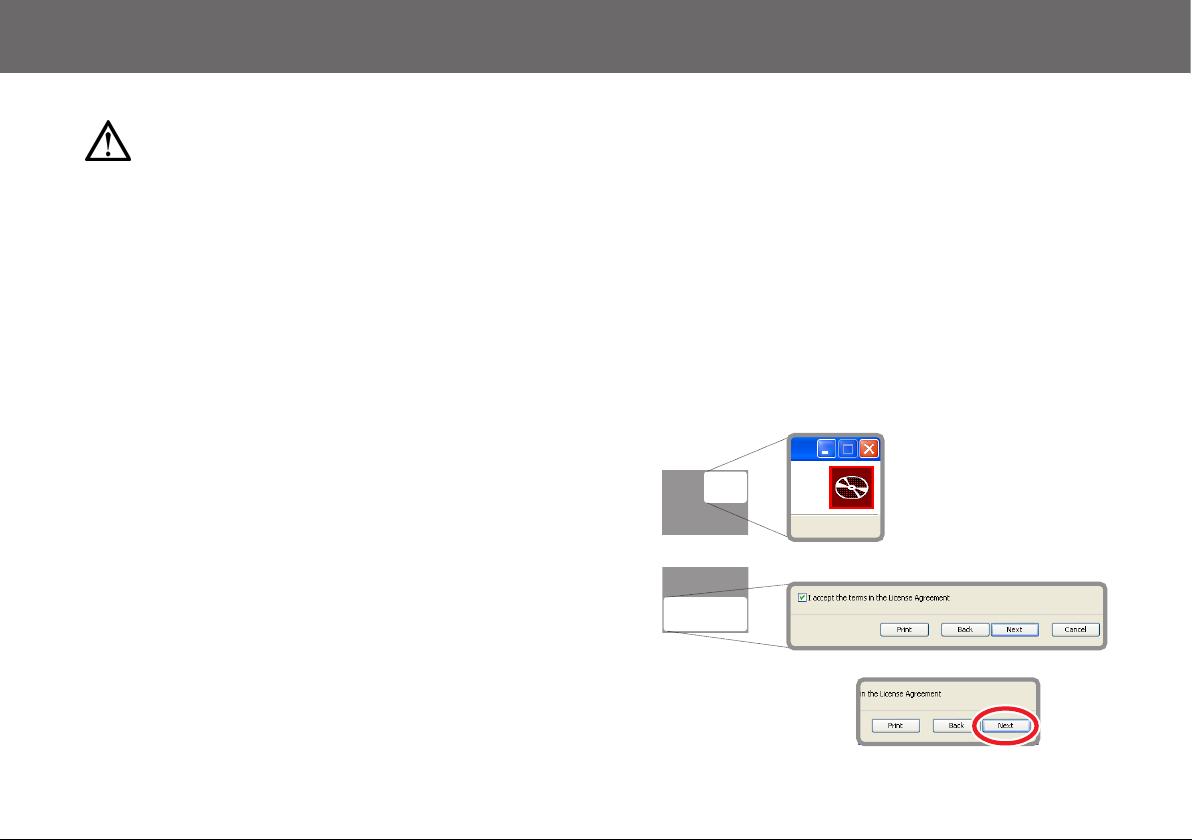
Using this Manual
In some sections this manual uses zoomed screenshots to display the
relevant area of the screen or window. The user is guided to the
relevant area by a series of navigation icons which indicate the portion
of the screen being zoomed. Two examples are shown below:
Top right hand quarter
of the window
Bottom half of the window
A specific feature is further
highlighted using a red
outline ring.
3
Components and Connections
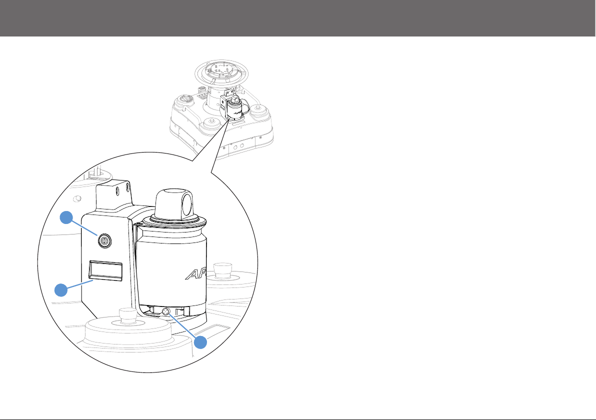
Left Side View
3
2
1 . . . . . . . . . . . . . . . . . . . . . . . . . . . . . . . . . . . . . . . . . . . RS232 Socket
2 . . . . . . . . . . . . . . . . . . . . . . . . . . . . . . . . . . . . . . . . . . . . .LCD display
3 . . . . . . . . . . . . . . . . . . . . . . . . . . . . . . . . . . . . . . . . . . . .Power switch
1
4
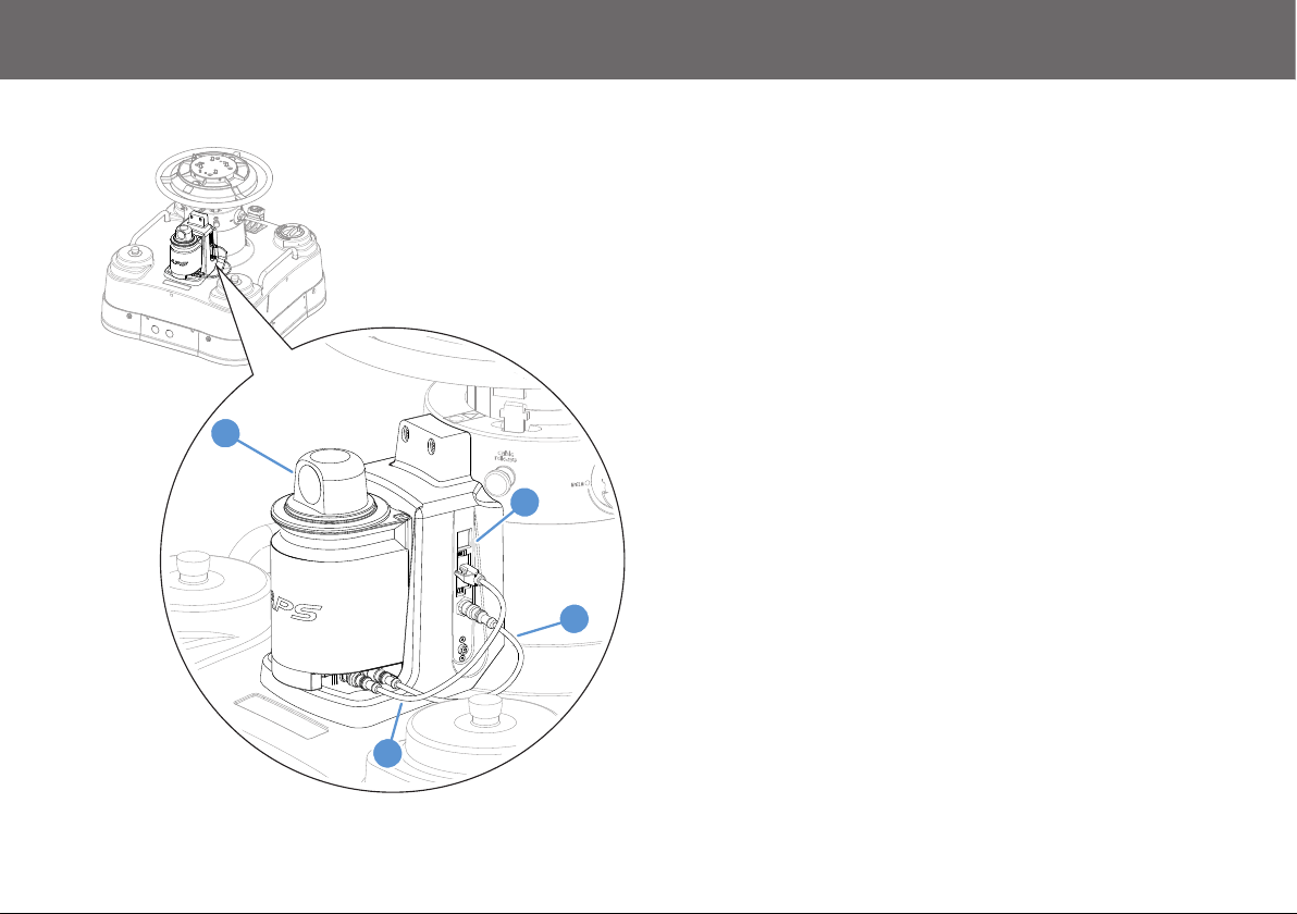
Right Side View
4
Components and Connections
5
6
4 . . . . . . . . . . . . . . . . . . . . . . . . . . . . . . . . Rotating laser scanner head
5 . . . . . . . . . . . . . . . . . . . . . . . . . . . . . . . . . . . . . . . . . . . Ethernet ports
6 . . . . . . . . . . . . . . . . . . . . . . . . . . . . . . . . Power interconnecting cable
7 . . . . . . . . . . . . . . . . . . . . . . . . . . . . . . . . . Data interconnecting cable
7
5
Installation
APS Scanner Function
When operational, the APS scanner provides absolute positioning data
for the pedestal. This is achieved with a rotating infrared laser scanner
head. When the infrared beam is reflected back from the APS reflective
targets installed in the studio, the absolute position of the pedestal on
the studio floor can be established and sent to the control system.
APS Scanner Safety
The laser scanner rotates at a rate of eight revolutions per second and
therefore the following safety points must be adhered to:
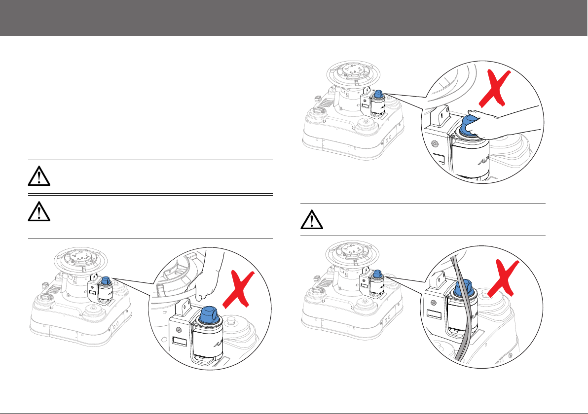
WARNING! Risk of personal injury. Do not hold the steering
ring in the proximity of the laser scanner when the pedestal
column is in a lowered position.
WARNING! Risk of personal injury or injury to others. Do
not attempt to touch the laser scanner on the APS scanner
unit while it is in motion. Warn other personnel and visitors
in the studio to the potential risk.
CAUTION! Risk of product damage. Do not route cables or
place objects near the rotating laser scanner head.
6
Installation
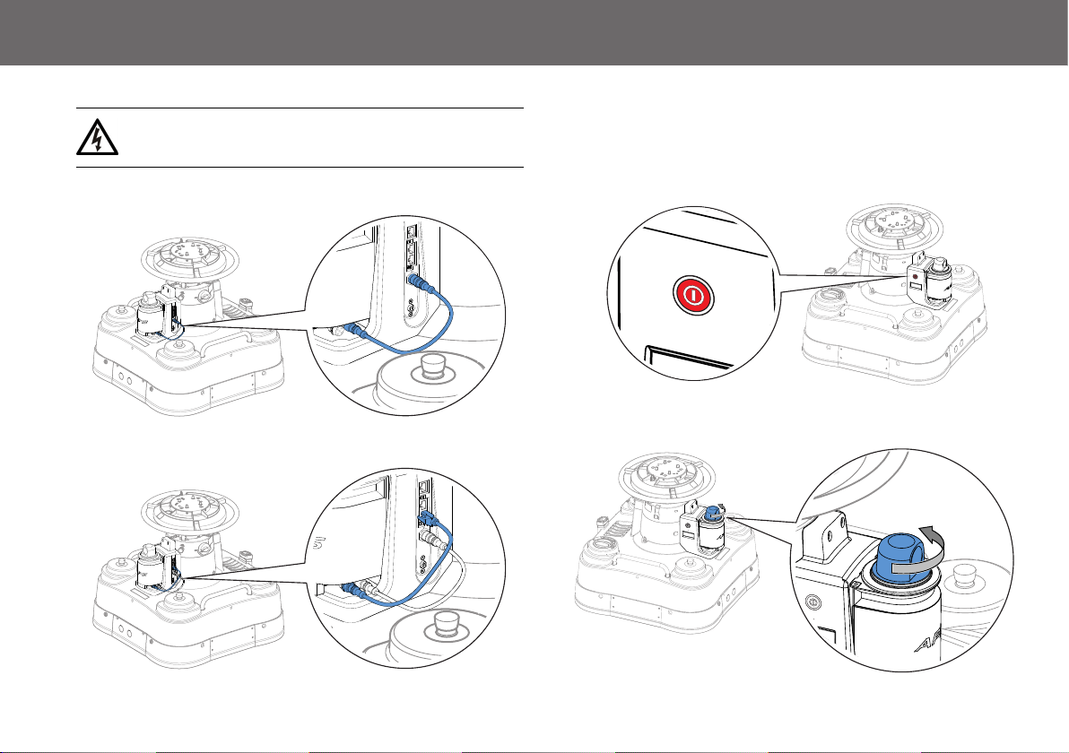
Electrical Connections
WARNING! Disconnect power from the pedestal before
attempting any electrical connections.
Power Interconnection
Data Interconnection
Powering Up
Before powering up the APS scanner, ensure that all external cable
connections are secured correctly. The pedestal must also be powered
up.
1. To power up, operate the on/off push button switch.
2. The power switch and LCD display will illuminate and the laser
scanner head will rotate.
7

Configuration
Configuring the APS Scanner
Before the APS system is fully operational, reflective targets must be
correctly installed into the studio environment and the APS scanner
must be configured to work with them. For configuration purposes, the
APS scanner has a built in user interface which is accessed by
connecting up a computer with compatible network settings running a
web browser such as Internet Explorer.
Reflective Target Installation
The APS scanner will only function in a studio with APS reflective
targets installed. For more information on the correct installation and
use of the APS reflective targets, refer to the APS Reflective Targets
Installation Guide, publication part No. V4109-4981.
The APS Scanner User Interface
The network settings of the computer must be changed for successful
connectivity with the APS scanner. The procedure for changing the
settings differs between Windows XP and Windows 7.
Changing the Network Settings Using Windows XP
1. From the Windows Start menu navigate to Control Panel >
Network Connections to open the Network Connections
window.
2. Right-click on the Local Area Connection icon and select
Properties from the menu.
3. Scroll down and select Internet Protocol (TCP/IP) and click the
Properties button.
4. The Internet Protocol (TCP/IP) Properties window opens.
a) Make a note of any current configuration settings in this
window so that they can be restored when required.
b) Click to select the Use the following IP address option.
c) Enter 192.168.1.5 (or an address appropriate for the device or
system) into the IP address field.
d) Press the Tab key to automatically populate the Subnet mask
field.
5. Click Ok to save the changes and exit the window.
6. Click Close to exit the Local Area Connection Properties
window.
8

Configuration
Changing the Network Settings Using Windows 7
1. From the Windows Start menu click to select Control Panel.
2. Click to select Network and Internet.
3. Click to select Network and Sharing Center.
4. Click on Change adaptor settings.
5. Right-click on the active local area connection and select
Properties from the menu.
6. The Local Area Connection Properties window opens. Click to
select Internet Protocol Version 4 (TCP/IPv4).
7. Click the Properties button.
8. The Internet Protocol Version 4 (TCP/IPv4) Properties window
opens.
a) Make a note of any current configuration settings displayed,
so that they can be restored when required.
b) Click to select the Use the following IP address option.
c) Enter 192.168.1.5 (or an address appropriate for the device or
system) into the IP address field.
d) Press the Tab key to automatically populate the Subnet mask
field.
9. Click Ok to save the changes and exit the window.
10. Click Ok again to exit the Local Area Connection Properties
window.
9

Configuration
Creating a Landmark Map
The APS user interface is used to scan the locations of the reflective
targets in the studio to create a landmark map. This map is then stored
by the APS scanner and used to provide accurate pedestal positional
data anywhere on the studio floor.
Starting Up
1.
Connect the configured computer to a spare network port on the
APS scanner using an Ethernet cable.
3. Power up the APS unit.
The LCD display will
initially show a boot up
screen and then change to
the main display screen.
Positional values are
displayed with a # symbol
indicating that mapping is
required.
4. Launch the web browser and type http://192.168.1.70 in the
address bar.
5. The user interface
home page opens, with
information displayed
about the firmware and
hardware versions of
the APS scanner unit.
Links to the other main
pages of the user
interface are also
provided here.
2. Power up the pedestal. If the pedestal has previously been used
and has pre-stored shots referenced to a floor target, perform the
standard floor targeting procedure.
10

Configuration
Target Type Selection
Before a landmark map can be created, the type of reflective targets
used in the studio installation must be programmed into the APS
scanner.
1. From the home page, click to select Landmark Detection from
the row of page links above the information table.
2. On the landmark detection page, select the reflector type being
used in the studio:
Select if the
studio is using
the wall mounted
flat reflectors
Select if the
studio is using
the cylindrical
bollard reflectors
The size of the
installed reflectors can
be change if required
(default sizes are 76
mm diameter for the
bollard and 75 mm
width for the flat
targets)
settings2
Click to store any
changes to the
target settings
Landmark Map Scanning
1.
Click to select the Landmark Mapping link.
2. Check that the option Replace in current layer is selected.
3. Click the Map Landmarks button to begin the scanning process.
4. When the scan has been completed, the landmark mapping page
updates with the following information:
The position of
the pedestal
The number of
scans performed
to create the
landmark map
The number of landmarks
(reflective targets) detected
during the mapping process
11

Configuration
5. Click the Save
Landmark Map to store
the scanned information.
A confirmation page
opens.
6. This returns the APS scanner unit to normal operation. The LCD
display will now show the following information:
The current position
of the pedestal
X: 1120.7
Y: 1905.5
Q: -12.697
Mode: Nav
Current mode is
navigation mode
layer
dev
lmark
: 0
: 2
: 6
The number of landmarks
(reflective targets)
currently visible to the
APS scanner unit
Adding Additional Targets to a Landmark Map
Additional reflective target locations can be added to the current
landmark map at any time. Common scenarios for this requirement are:
• Additional reflective targets have been installed in the studio
• Previously obscured reflective targets have come into view of the
APS scanner at the current pedestal location in the studio
• Additional previously unmapped reflective targets have come into
view at a different position in the studio
The APS scanner can be instructed to scan for previously unmapped
targets and add them to the current landmark map.
1. Click to select the Landmark Mapping link from any page in the
APS user interface.
2. On the landmark mapping page, tick to select Negative Mapping
and Append to current layer.
3. Click the Map Landmarks button. The APS scanner unit will only
scan for previously undetected targets. When the scan is
complete:
Click to store the new
targets to the current
landmark map
The number of new
targets detected
12

Configuration
Adding Additional Landmark Maps
Additional landmark maps can be scanned and stored in the APS
scanner. This is useful if the APS pedestal is used in several different
studios. Any additional landmark maps are stored as different layers in
the memory of the APS scanner and can be recalled at any time. The
APS scanner can store up to 320 layers.
Creating a New Layer
1. On the landmark mapping page, change the Layer from the
default value of 0 to a number between 1 and 319.
2. Follow the procedure described in the section Landmark Map
Scanning on page 11 to scan and store a new landmark map to
the new layer number.
3. The LCD display also
indicates the new layer
number and number of
landmarks (targets) currently
detected.
Managing Layers
To change between stored layers:
X: 1040.5
Y: 1720.4
Q: -10.265
Mode: Nav
layer
dev
lmark
: 1
: 3
: 4
1. Click to select the Positioning link from any page in the APS user
interface.
2. On the positioning page change the Current Layer field number to
the layer required and click Save.
Replacing a Landmark Map
The currently selected landmark map can be completely replaced. This
can be particularly useful if many of the installed reflective targets in the
studio have been moved.
1. On the scanner mode page, click the Standby Mode button and
then click to select the Landmark Mapping link.
2. On the landmark mapping page select Replace in current layer.
3. Check that Negative Mapping is not selected.
4. Click the Map Landmarks button. The APS scanner unit will
create a new landmark map using all the available reflective
targets.
5. Click the Save Landmark Map button to overwrite all previous
mapping data stored on the selected layer.
13

Configuration
Advanced Settings
CAUTION! Only competent trained personnel should make
changes to setup options or parameters using the APS user
interface. Changing these settings could affect the reliability
of the system.
The APS user interface can be used to configure advanced system
settings to enhance performance and positional accuracy in an
installed location. Adjusting the default settings can also help the
operator if problems are being experienced during basic operation.
If the APS system is performing accurately and
consistently, there is no need to change any default
Note
Defaults
Landmark Settings
The following parameters used by the APS scanner when scanning for
reflective targets in the landmark map can be changed:
Action Radius - The APS scanner can detect targets between a
minimum distance of 0.5 m and a maximum distance of 70 m from the
laser scanner head. However, in some installations it may not be
desirable or necessary to detect targets in such a large field of view, so
the range can be reduced to suit the studio size.
N closest reflectors - This parameter limits the number of targets the
APS scanner uses during scanning, starting with the closest targets
first. This can help to improve accuracy because only the closest
settings.
To restore the APS scanner to the factory default settings,
see Default Settings on page 17 in the Troubleshooting
section.
targets in the map will be scanned. The default setting is 0, which is a
special case allowing all available targets to be detected. A minimum
detection of three targets is required for the APS scanner to produce
positional information.
Reflector Threshold - This parameter changes the sensitivity of the
APS scanner when detecting targets. If the APS scanner is interpreting
other reflective surfaces in the studio as targets, the threshold
percentage can be increased to help minimise the effect of false
readings on system performance.
1. Click to select the Landmark Detection link from any page in the
APS user interface.
2. On the landmark detection page the following detection
parameters can be adjusted:
Increase the
minimum, or
decrease the
maximum field
values. The APS
scanner will then
only detect
targets within the
reduced range
Set a value to limit
the number of
targets the
scanner will detect
(closest only)
Adjust the percentage
to change the sensitivity
of the scanner
settings2
Click to store any
changes to the
detection settings
14

Configuration
Position Settings
The following positioning settings that the APS system uses during
normal operation can be changed:
Sliding Mean Depth - This setting relates to the number of scans
(rotations) performed by the APS scanner to detect the positions of
mapped targets. The default setting is one scan, however if this is set
to a multiple number the target data results collected from each scan is
averaged out. Increasing the number of scans can help to improve
target detection if scanning errors often occur due to other moving
objects in the studio.
The APS scanner performs eight scans (rotations) per
Note
Radius of landmark detection window - This parameter affects the
APS scanner’s ability to accurately resolve precise target locations.
The default is set to a radius of 300 mm. This means that the APS
system will assume that a true landmark position has been resolved if
a reflective object has been detected within 300 mm of a known target
position in the landmark map. If two targets appear very close together
due to a particular angular line of sight, or there is a known reflective
object other than a true reflective target close by, the window radius
could be reduced. This would have the effect of narrowing the focus for
target detection and help to separate close reflective objects in problem
scenarios, thus improving positional accuracy.
Note
second.
The radius of the landmark detection window can be set
independently at the minimum and maximum ranges of the
detection field.
1. Click to select the Positioning link from any page in the APS user
interface.
2. On the positioning page the following parameters can be adjusted:
Increase the number
of scans made to
detect targets
Increase or decrease
the detection window
at both ends of the
scanning range
Click to store any
changes to the
positioning settings
15

Maintenance
Routine Maintenance
The APS scanner requires minimal routine maintenance, apart from
checking the connections and overall operation periodically.
Routine Checks
During use, check the following:
• Check cables for signs of wear or damage. Replace as necessary
• Check that all cables are connected properly
WARNING! Risk of electric shock. Always check cables
for signs of damage. Damaged cables can cause personal
injury and/or damage the equipment.
Cleaning
WARNING! Risk of electric shock. Always disconnect and
isolate the product from the power supply before cleaning.
APS Scanner
During normal use the only cleaning required should be a regular wipe
over with a dry, lint-free cloth. Dirt accumulated during storage or
periods of disuse may be removed with a vacuum cleaner. Particular
attention should be paid to all connection ports.
Laser Scanner Window
CAUTION! Potential performance reduction due to
contamination of the window in the laser scanner. The
window must be regularly cleaned as described.
WARNING! Switch off the APS scanner before cleaning the
laser read head window.
Static charges cause dust particles to be attracted to the window of the
laser scanner.
To clean the window, proceed as follows:
1
Use a clean and soft brush to remove dust particles
from the window.
16
2
Carefully wipe the window using a clean and damp
lens cloth.

Troubleshooting
Default Settings
The following table lists the factory default setting values for the APS scanner.
Landmark Detection Default Value Positioning Default Value
Cylindrical Reflector Size 76 mm Reflector Threshold 50%
Flat Reflector Size 75 mm Sliding Mean Depth 1
Action Radius (Min) 500 mm Radius of landmark detection window at (distLow) 300 mm at 500 mm distance
Action Radius (Max) 70000 mm Radius of landmark detection window at (distHigh) 300 mm at 70000 mm distance
N closest reflectors 0
APS Scanner Function
Fault Check Comments
The APS scanner is switched on,
but the power switch and LCD
display are not illuminated and the
laser scanner head is not rotating.
The pedestal is not maintaining
consistent and accurate absolute
positioning during normal
operation.
Check that all the interconnections on the APS scanner are
secure.
Check that the Fusion pedestal is connected to the power source
supply and switched on.
Check that the APS scanner has a clear view of the reflective
target positions (no obstructions) and they are in the correct
installation positions.
The APS scanner needs contact with at least three reflective
targets.
Repeat the landmark map scan procedure, appending any new
or moved reflective targets to the current landmark map.
See Electrical Connections on
page 7.
See the APS Reflective Targets
Installation Guide, publication part
No. V4109-4981.
See Adding Additional Targets to a
Landmark Map on page 12.
17

Troubleshooting
Fault Check Comments
The pedestal is no longer
maintaining consistent and
accurate absolute positioning.
The APS scanner is not updating
or displaying pedestal positional
information.
Check the laser scanner window for dust
contamination and clean as necessary.
Check the laser scanner window for possible
damage (scratches, cracks or fracture).
Check that the APS scanner is set to navigation
mode.
Check that the APS scanner is set to the correct
layer number for the current studio location.
LCD Display Messages
If the APS scanner detects a problem or fault during use, it is shown on the LCD display.
Display Fault/Check Comments
Communication or power problem with the APS scanner.
Check all interconnections and that the pedestal is
powered up.
Communication has not been established between the
APS scanner and the pedestal. Check that the pedestal is
powered up and working with the control system.
See Laser Scanner Window on page 16.
If the window is damaged it may need to be replaced.
Contact Vinten Radamec customer support.
On the scanner mode page, click on the Navigation
Mode button to return the APS system to normal
operation.
See Managing Layers on page 13.
See Electrical Connections on page 7.
18

Troubleshooting
.
Display Fault/Check Comments
Pedestal positional information not displayed. The APS
scanner requires the landmark mapping procedure to be
carried out.
The APS scanner has not booted correctly. Try power
cycling the scanner and the pedestal.
The APS scanner has not located the memory card, or
the memory card is incorrectly formatted.
See Landmark Map Scanning on page 11.
If the problem persists, contact Vinten Radamec.
Contact Vinten Radamec.
19

General Notices
Technical Specification
Dimensions
Weight. . . . . . . . . . . . . . . . . . . . . . . . . . . . . . . . . . . . . . . 3.7 Kg (8.2 lb)
Height . . . . . . . . . . . . . . . . . . . . . . . . . . . . . . . . . . . . 257 mm (10.1 in.)
Width. . . . . . . . . . . . . . . . . . . . . . . . . . . . . . . . . . . . . . 177 mm (7.0 in.)
Length. . . . . . . . . . . . . . . . . . . . . . . . . . . . . . . . . . . . . 211 mm (8.3 in.)
Power
DC power input . . . . . . . . 24V DC (supplied directly from the pedestal)
Environmental
Temperature range (operation) . . . . . . . 0°C to +40°C (32°F to +104°F)
Pedestal Accuracy
X/Y accuracy. . . . . . . . . . . . . . . . . . . . . . . . . . . . . . . . . . . . . . .±25 mm
Angular accuracy . . . . . . . . . . . . . . . . . . . . . . . . . . . . . . . . . . . . . ±0.1°
Laser Scanner Specification
Laser light wavelength . . . . . . . . . . . . . . . . 905 nm, infrared, eye safe
Laser Compliance
• Complies with laser class 1 in accordance with IEC 60825-1
• Complies with 21 CFR 1040.10 and CFR1040.11 except for
deviations pursuant to laser notice No.50 dated June 24th, 2007
FCC Certification
APS Scanner Unit
V4109-0001
V4109-0002
FCC Notice
This product complies with the limits for a Class B digital device,
pursuant to Part 15 of the FCC Rules. These limits are designed to
provide reasonable protection against harmful interference in a
residential installation. This equipment generates, uses and can radiate
radio frequency energy and, if not installed and used in accordance
with the instructions, may cause harmful interference to radio or
television reception, which can be determined by turning the equipment
off and on, the user is encouraged to try to correct the interference by
one or more of the following measures:
• Reorient or relocate the receiving antenna
• Increase the separation between the equipment and receiver
• Connect the equipment into an outlet on a circuit different from that
to which the receiver is connected
• Consult the dealer or an experienced radio/television technician
for assistance
FCC Warning
Changes or modifications not expressly approved by the party
responsible for compliance could void the user's authority to operate
the equipment.
20

General Notices
FCC Declaration of Conformity
This product complies with Part 15 of the FCC Rules, Operation is
subject to the following two conditions:
1.This product may not cause harmful interference.
2.This product must accept any interference received, including
interference that may cause undesired operations.
Declaration of Conformity
Vitec Videocom Limited declares that this product has been
manufactured in accordance with BS EN ISO 9001:2008 and is in
compliance with the essential requirements and other relevant
provisions of the Machinery Directive 2006/42/EC. A copy of the
Declaration of Conformity is available upon request.
Environmental Considerations
ROHS Compliance Statement
Vitec Videocom Limited is compliant with the European Union Directive
2002/95/EC Restrictions of Hazardous Substances (RoHS) that
restricts the use of hazardous substances in Electrical and Electronic
Equipment.
European Union Waste Electrical and Electronic
Equipment (WEEE) Directive (2002/96/EC)
This symbol marked on the product or its packing indicates that this
product must not be disposed of with general household waste. In
some countries or European Community regions, separate collection
systems have been set up to handle the recycling of electrical and
electronic waste products. By ensuring this product is disposed of
correctly you will help prevent potentially negative consequences for
the environment and human health. The recycling of materials helps
conserve natural resources.
Visit our website for information on how to safely dispose of this product
and its packaging.
In Countries Outside the EU:
Dispose of this product at a collection point for the recycling of electrical
and electronic equipment according to your local government
regulations.
Pollution Statement
This equipment is designed for operation in Pollution Degree 2
environments.
21


VAVinten Radamec
itec Group brand
Publication part No. V4109-4980/1
 Loading...