

Fusion FPR-210
Manual and Robotic Pedestal
+
Fusion FPR-210 Pedestal
+
Operators Guide
Part Nos. V3952-0005
www.vintenradamec.com

Publication Part No. V3952-4987
Published by
Vitec Videocom Ltd
Supports Technical Publications Department
Western Way, Bury St Edmunds
Suffolk
IP33 3TB
United Kingdom
Email: technical.publications@vitecgroup.com
Copyright © 2014
All rights reserved.
Original Instructions: English
All rights reserved throughout the world. No part of this
document may be stored in a retrieval system, transmitted,
copied or reproduced in any way, including, but not limited
to, photocopy, photograph, magnetic or other record
without the prior agreement and permission in writing of
the Vitec Group plc.
Trademark acknowledgements
All product trademarks and registered trademarks are the
property of The Vitec Group Plc.
All other trademarks and registered trademarks are the
property of their respective companies.
Disclaimer
The information contained in this manual is believed to be
correct at the time of printing. Vitec Videocom Ltd reserves
the right to make changes to the information or specifications
without obligation to notify any person of such revision or
changes. Changes will be incorporated in new versions of the
publication.
We are making every effort to ensure that our manuals are
updated on a regular basis to reflect changes to product
specifications and features. Should this manual not contain
information on the core functionality of your product, please let
us know. You may be able to access the latest revision of this
manual from our website.
Vitec Videocom Ltd. Reserves the right to make changes to
product design and functionality without notification.

Operators guide
Contents
Page
Safety instructions . . . . . . . . . . . . . . . . . . . . . . . . . . . . . . . . . . . . . . . . . . . . . . . . . 2
Components and connectors . . . . . . . . . . . . . . . . . . . . . . . . . . . . . . . . . . . . . . . . 4
Introduction and description. . . . . . . . . . . . . . . . . . . . . . . . . . . . . . . . . . . . . . . . 10
Column. . . . . . . . . . . . . . . . . . . . . . . . . . . . . . . . . . . . . . . . . . . . . . . . . . . . . . . . . . . . . . . 10
Base. . . . . . . . . . . . . . . . . . . . . . . . . . . . . . . . . . . . . . . . . . . . . . . . . . . . . . . . . . . . . . . . . 10
Installation. . . . . . . . . . . . . . . . . . . . . . . . . . . . . . . . . . . . . . . . . . . . . . . . . . . . . . . 11
Unpacking . . . . . . . . . . . . . . . . . . . . . . . . . . . . . . . . . . . . . . . . . . . . . . . . . . . . . . . . . . . . 11
Steering mechanism checks . . . . . . . . . . . . . . . . . . . . . . . . . . . . . . . . . . . . . . . . . . . . . . 11
Fitting the load . . . . . . . . . . . . . . . . . . . . . . . . . . . . . . . . . . . . . . . . . . . . . . . . . . . . . . . . . 11
Pressurising the pedestal. . . . . . . . . . . . . . . . . . . . . . . . . . . . . . . . . . . . . . . . . . . . . . . . . 14
Electrical connections . . . . . . . . . . . . . . . . . . . . . . . . . . . . . . . . . . . . . . . . . . . . . . . . . . . 16
Height control box installation . . . . . . . . . . . . . . . . . . . . . . . . . . . . . . . . . . . . . . . . . . . . . 19
Operation. . . . . . . . . . . . . . . . . . . . . . . . . . . . . . . . . . . . . . . . . . . . . . . . . . . . . . . . 20
Parking brake. . . . . . . . . . . . . . . . . . . . . . . . . . . . . . . . . . . . . . . . . . . . . . . . . . . . . . . . . . 20
Cable clamp . . . . . . . . . . . . . . . . . . . . . . . . . . . . . . . . . . . . . . . . . . . . . . . . . . . . . . . . . . . 20
Cable guard . . . . . . . . . . . . . . . . . . . . . . . . . . . . . . . . . . . . . . . . . . . . . . . . . . . . . . . . . . . 21
Using the column lock . . . . . . . . . . . . . . . . . . . . . . . . . . . . . . . . . . . . . . . . . . . . . . . . . . . 21
Steering . . . . . . . . . . . . . . . . . . . . . . . . . . . . . . . . . . . . . . . . . . . . . . . . . . . . . . . . . . . . . . 23
Switching on. . . . . . . . . . . . . . . . . . . . . . . . . . . . . . . . . . . . . . . . . . . . . . . . . . . . . . . . . . . 23
Operating the Pedestal . . . . . . . . . . . . . . . . . . . . . . . . . . . . . . . . . . . . . . . . . . . . . . . . . . 23
Movement indicators . . . . . . . . . . . . . . . . . . . . . . . . . . . . . . . . . . . . . . . . . . . . . . . . . . . . 24
Emergency stops . . . . . . . . . . . . . . . . . . . . . . . . . . . . . . . . . . . . . . . . . . . . . . . . . . . . . . . 24
Collision detection . . . . . . . . . . . . . . . . . . . . . . . . . . . . . . . . . . . . . . . . . . . . . . . . . . . . . . 24
Referencing the studio datum position. . . . . . . . . . . . . . . . . . . . . . . . . . . . . . . . . . . . . . . 25
Transportation and storage . . . . . . . . . . . . . . . . . . . . . . . . . . . . . . . . . . . . . . . . . . . . . . . 26
Maintenance . . . . . . . . . . . . . . . . . . . . . . . . . . . . . . . . . . . . . . . . . . . . . . . . . . . . . 27
General . . . . . . . . . . . . . . . . . . . . . . . . . . . . . . . . . . . . . . . . . . . . . . . . . . . . . . . . . . . . . . 27
Routine checks . . . . . . . . . . . . . . . . . . . . . . . . . . . . . . . . . . . . . . . . . . . . . . . . . . . . . . . . 27
Adjustments . . . . . . . . . . . . . . . . . . . . . . . . . . . . . . . . . . . . . . . . . . . . . . . . . . . . . . . . . . . 27
Cleaning. . . . . . . . . . . . . . . . . . . . . . . . . . . . . . . . . . . . . . . . . . . . . . . . . . . . . . . . . . . . . . 27
Fuse replacement . . . . . . . . . . . . . . . . . . . . . . . . . . . . . . . . . . . . . . . . . . . . . . . . . . . . . . 28
Parts list . . . . . . . . . . . . . . . . . . . . . . . . . . . . . . . . . . . . . . . . . . . . . . . . . . . . . . . . 29
Main assemblies . . . . . . . . . . . . . . . . . . . . . . . . . . . . . . . . . . . . . . . . . . . . . . . . . . . . . . . 29
Transport fixings. . . . . . . . . . . . . . . . . . . . . . . . . . . . . . . . . . . . . . . . . . . . . . . . . . . . . . . . 29
Optional accessories . . . . . . . . . . . . . . . . . . . . . . . . . . . . . . . . . . . . . . . . . . . . . . . . . . . . 29
Technical data. . . . . . . . . . . . . . . . . . . . . . . . . . . . . . . . . . . . . . . . . . . . . . . . . . . . 29
Declaration of conformity . . . . . . . . . . . . . . . . . . . . . . . . . . . . . . . . . . . . . . . . . . 31
Environmental considerations . . . . . . . . . . . . . . . . . . . . . . . . . . . . . . . . . . . . . . 31
1
Fusion FPR-210+ pedestal
Safety instructions
Important information on the safe
installation and operation of this product.
Read this information before operating the
product. For your personal safety, read
these instructions. Do not operate the
product if you do not understand how to
use it safely. Save these instructions for
future reference.
Warning Symbols Used in
these Instructions
Safety cautions are included in these
instructions. These safety instructions must be
followed to avoid possible personal injury and
avoid possible damage to the product
WARNING!
Where there is a risk of personal
injury or injury to others, comments
appear supported by the warning
triangle symbol. Where there is a
risk of damage to the product,
associated equipment, process or
surroundings, comments appear
supported by the word ‘Caution’.
ELECTRIC SHOCK
Where there is a risk of electric
shock, comments appear supported
by the hazardous voltage warning
triangle.
WARNING!
130 kg/286.6 lb LIFTING AID
REQUIRED. Use a lifting hoist
capable of safely lifting the product.
The product is intended for use by television
camera operators, trained to use Vinten
Radamec robotic equipment. Do not use this
product for any other purpose other than that
specified in this usage statement.
Electrical Connection
CAUTION! This product must be
connected to a power supply of the
same voltage (V) and current (A) as
indicated on the product. Refer to
the Technical Specifications for the
product.
CAUTION! We recommend that you
use the power supply cable supplied
with the product.
CAUTION! Always use a fuse of the
correct type and rating for the
product. Refer to the Technical
Specifications for the product.
CAUTION! Using alternative power
sources will invalidate the system
EMC liability.
Basic Electrical Insulation
(Class 1 equipment)
WARNING! This product is Class 1
equipment. For safe operation this
equipment must be connected to a
power supply that has a protective
earth connection (US: ground).
Intended Use
This product is designed for use within
television studios to support a payload
weighing up to 95 kg (210 lb). The total
payload must not be exceeded. The FPR210+ pedestal can be moved manually or
remotely to allow operators to control their
movements and positioning around the
studio.
2
Operators guide
Mounting and Installation
WARNING! Always ensure that all
power and auxiliary communications
cables are routed so that they do not
present any danger to personnel.
Take care when routing cables in
areas where robotic equipment is in
use.
Water, Moisture and Dust
WARNING! Protect the product from
water, moisture and dust. The
presence of electricity near water
can be dangerous.
Operating Environment
CAUTION! The product should not
be used outside the operating
temperature limits. Refer to the
product Technical Specifications for
the operating limits for the product.
Cleaning
WARNING! Risk of electric shock.
Always disconnect and isolate the
product from the power supply
before cleaning.
CAUTION! Do not use solvent or oilbased cleaners, abrasives or wire
brushes. Only use detergent-based
cleaners.
Safety when working with
Robotic Equipment
In normal operation remote-controlled
equipment can move suddenly and without
warning. Since audible warnings are not
suitable for use within the studio environment,
it is recommended that only trained personnel
be allowed to work in the active areas where
remote-controlled heads and pedestals are
located. The safe operating zone is a
minimum of 1 m (3 ft).
Safety Notes for Operators
Operators must familiarise themselves with
the working footprint of the robotic head,
including all associated equipment (lens,
zoom and focus controls, viewfinder,
prompter, etc.) to prevent inadvertent
collisions or injury to personnel.
If personnel are too close to a head or
pedestal that is about to move, the operator
should prevent the motion from starting or stop
the motion if it has started.
We strongly recommend that the operator
verifies visually that the active area is clear of
hazards and personnel, both before and
during remote operation.
Maintenance
WARNING! The fitting of non-
approved parts and accessories, or
the carrying out of non-approved
alterations or servicing can be
dangerous and could affect the
safety of the product. It may also
invalidate the terms and conditions
of the product warranty.
3
Fusion FPR-210+ pedestal
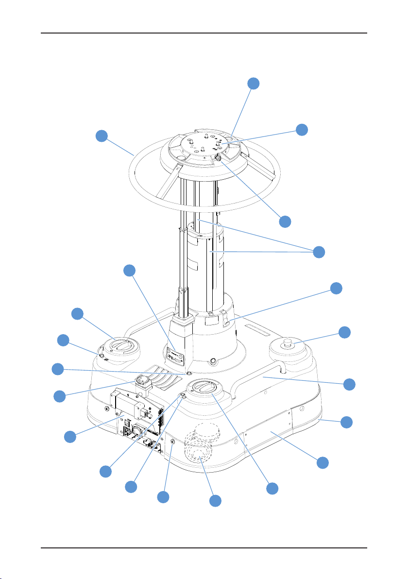
Components and connectors
1
17
16
18
19
21
2
3
4
20
5
6
7
8
15
14
13
12
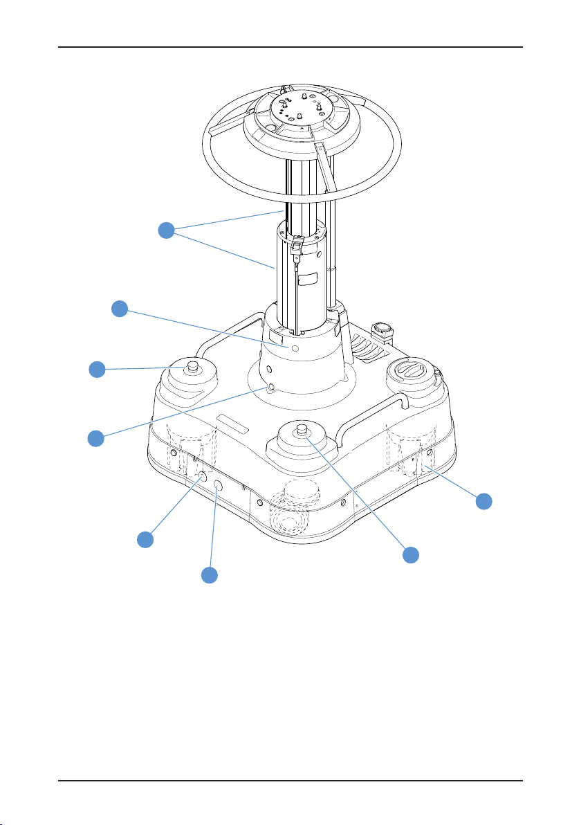
Fig. 1 Fusion FP-210+ Pedestal (South East view)
11
10
9
4

Operators guide
[1] . . . . . . . . . . . . . . . . . . . . . . . . . . . . . . . . . . . . . . . . . . . . . . . . . . . . . . . . . . . Pressure gauge
[2] . . . . . . . . . . . . . . . . . . . . . . . . . . . . . . . . . . . . . . . . . . . . . . . . . . . . . . . .Head mounting plate
[3] . . . . . . . . . . . . . . . . . . . . . . . . . . . . . . . . . . . . . . . . . . . . . . . . . . . . . Schrader valve and cap
[4] . . . . . . . . . . . . . . . . . . . . . . . . . . . . . . . . . . . . . . . . . . . . . Column bearing strip (3 per stage)
[5] . . . . . . . . . . . . . . . . . . . . . . . . . . . . . . . . . . . . . . . . . . . . . . . . . . . . . . . . . . . . . . Column lock
[6] . . . . . . . . . . . . . . . . . . . . . . . . . . . . . . . . . . . . . . . . . . . . . . . . . . . . . .Emergency stop button
[7] . . . . . . . . . . . . . . . . . . . . . . . . . . . . . . . . . . . . . . . . . . . . . . . . . . . . . . . . . . . . .Lifting handles
[8] . . . . . . . . . . . . . . . . . . . . . . . . . . . . . . . . . . . . . . . . . . . . . . . Bumper strip/collision detection
[9] . . . . . . . . . . . . . . . . . . . . . . . . . . . . . . . . . . . . . . . . . . Alignment sensor/wheel access panel
[10] . . . . . . . . . . . . . . . . . . . . . . . . . . . . . . . . . . . . . . . . Automatic/manual steering mode knob
[11] . . . . . . . . . . . . . . . . . . . . . . . . . . . . . . . . . . . . . . . Double castor wheels (non-driven, 2 off)
[12] . . . . . . . . . . . . . . . . . . . . . . . . . . . . . . . . . . . . . . . . . . . . . . . .Cable guard lowering buttons
[13] . . . . . . . . . . . . . . . . . . . . . . . . . . . . . . . . . . . . . . . . . . . . . . . . . . . . . . Bumper manual reset
[14] . . . . . . . . . . . . . . . . . . . . . . . . . . . . . . . . . . . . . . . . . . . . . Bumper sensitivity potentiometer
[15] . . . . . . . . . . . . . . . . . . . . . . . . . . . . . . . . . . . . . . . . . . . . . . . . Power box and ICE interface
[16] . . . . . . . . . . . . . . . . . . . . . . . . . . . . . . . . . . . . . . . . . . . . . . . . . . . . . . . . . . . . Cable clamps
[17] . . . . . . . . . . . . . . . . . . . . . . . . . . . . . . . . . . . . . . . . . . . . . . . . . . . . . . Height control socket
[18] . . . . . . . . . . . . . . . . . . . . . . . . . . . . . . . . . . . . . . . . . . . . . . . . . . . . . . . Parking brake slider
[19] . . . . . . . . . . . . . . . . . . . . . . . . . . . . . . . . . . . . . . . . CRAB/STEER mode changeover knob
[20] . . . . . . . . . . . . . . . . . . . . . . . . . . . . . . . . . . . . . . . . . . . . . . . . . . Height adjustment buttons
[21] . . . . . . . . . . . . . . . . . . . . . . . . . . . . . . . . . . . . . . . . . . . . . . . . . . . . . . . . . . . . . Steering ring
5
Fusion FPR-210+ pedestal
27
26
6
25
22
24
6
23
Fig. 2 Fusion FP-210+ Pedestal (North West view)
6

Operators guide
[22] . . . . . . . . . . . . . . . . . . . . . . . . . . . . . . . . . . . . . . . . . . . . . . Driven double-wheel sets (2 off)
[23] . . . . . . . . . . . . . . . . . . . . . . . . . . . . . . . . . . . . . . . USB configuration port (with cover plug)
[24] . . . . . . . . . . . . . . . . . . . . . . . . . . . . . . . . . . . . . . Servo configuration port (with cover plug)
[25] . . . . . . . . . . . . . . . . . . . . . . . . . . . . . . . . . . . . . . . . . . . Pedestal movement indicator (3 off)
[26] . . . . . . . . . . . . . . . . . . . . . . . . . . . . . . . . . . . . . . . . . . . . . . Blanking cover (do not remove)
[27] . . . . . . . . . . . . . . . . . . . . . . . . . . . . . . . . . . . . . . . . . . . . . . . . . . . . . . . . . . . Moving column
7
Fusion FPR-210+ pedestal
36
41
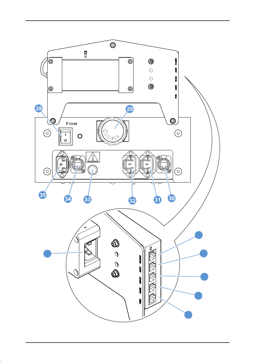
Fig. 3 Fusion VR Power Box and ICE Interface Connectors
37
38
39
40
8

Operators guide
[28] . . . . . . . . . . . . . . . . . . . . . . . . . . . . . . . . . . . . . . . . . . . . . . . . . . . . . Power ON/OFF switch
[29] . . . . . . . . . . . . . . . . . . . . . . . . . . . . . . . . . . . . . . . . . . . . . . . . . . . . . . . . . . . . . Cable clamp
[30] . . . . . . . . . . . . . . . . . . . . . . . . . . . . . . . . . . . . . . . . . . . . . . . . . . . . Ethernet port (auxiliary)
[31] . . . . . . . . . . . . . . . . . . . . . . . . . . . . . . . . . . . Power output socket 90–240V, 100 W (Head)
[32] . . . . . . . . . . . . . . . . . . . . . . . . . . . . . . . . . . . . . Power output socket 90–240V, 50 W (Aux)
[33] . . . . . . . . . . . . . . . . . . . . . . . . . . . . . . . . . . . . . . . . . . . . . . . . . . . . . . . . . . . . . . . . . . . Fuse
[34] . . . . . . . . . . . . . . . . . . . . . . . . . . . . . . . . . . . . . . . . . . . . . . . . .Ethernet port (ICE interface)
[35] . . . . . . . . . . . . . . . . . . . . . . . . . . . . . . . . . . . . . . . . . . . . . . . . . . . . . . Power socket (mains)
[36] . . . . . . . . . . . . . . . . . . . . . . . . . . . . . . . . . . . . . . . . . ICE Ethernet IN port (from floor cable)
[37] . . . . . . . . . . . . . . . . . . . . . . . . . . . . . . . . . . . . . . . . . . . ICE Ethernet primary auxiliary port
[38] . . . . . . . . . . . . . . . . . . . . . . . . . . . . . . . . . . . . . . . . . . . . . . . . . . . . .ICE Ethernet head port
[39] . . . . . . . . . . . . . . . . . . . . . . . . . . . . . . . . . . . . . . . . . ICE Ethernet secondary auxiliary port
[40] . . . . . . . . . . . . . . . . . . . . . . . . . . . . . . . . . . . . . . . . . . . . . . . . . . ICE Ethernet pedestal port
[41] . . . . . . . . . . . . . . . . . . . . . . . . . . . . . . . . . . . . . . . . . . . . . . . . . . . Power supply inlet socket
9

Fusion FPR-210+ pedestal
Introduction and description
This Operators Guide describes how to set up and operate the Fusion FPR-210
The FPR-210+ pedestal has been designed for integration with the Fusion FH/R-145 pan and tilt
heads and Vinten Radamec Control Systems (VRC) using the Intelligent Control Engineering
(ICE) system.
Each product within the Fusion FPR-210+ range of pedestals comprises a central two-stage,
telescopic column mounted in a moveable base. The base of the FPR-210+ pedestals are
motorised.
The pedestals can be operated manually by a camera operator within the studio or remotely
operated in robotic mode from a Fusion control system. The pedestals have a maximum payload
capacity of 95 kg (210 lb).
+.
Column
The telescopic column [27] is pressurised from an external pressure source. Controls on the
column comprise a column lock [5], which locks the column in the fully-depressed position, and
height adjustment buttons [20], which adjust the column height when in manual mode only. The
pedestal is provided with a standard four-bolt mounting interface [2].
Base
The base is carried on four sets of wheels [11, 22], two of which are driven and two freewheeling, mounted on a flexible chassis to accommodate uneven floors. A height-adjustable
cable guard is provided, which can be lowered by depressing the cable guard buttons [12]
located near each corner of the base. The guard can then be raised in predefined increments
as required. Emergency stop buttons [6], lifting handles [7] and a wheel brake slider [18] are
provided on the upper surface of the base. Rotary knobs allow the operator to switch between
conventional and crab steering [19] and manual and robotic operation [10].
The cable clamps [16, 29], main power switch [28] and both power [31, 32, 35] and data
connections [30, 34] can all be found on the South side (rear) of the base, with a USB
configuration port [23] located on the North side (front) of the base. The bumper strip [8] running
around the pedestal base contains collision detection sensors which arrest movement on
contact with an obstacle.
10

Operators guide
Installation
Unpacking
WARNING! 130kg/286.6 lb LIFTING AID REQUIRED. Use a lifting hoist capable
of safely lifting the product.
WARNING!
1. DO NOT lift the pedestal by the steering ring—use the lifting handles on
top of the pedestal base.
2. DO NOT release the column lock, if the pedestal pressure exceeds 4 bar
(60 psi) without a balancing load mounted. Reduce pressure as
necessary using the Schrader valve cap.
Unpack the pedestal ensuring that all transport packing and retaining fixings are removed,
including the Velcro strap (part no. 3320-268) securing the column lock.
Steering mechanism checks
1. Rotate the CRAB/STEER knob [19] counter-clockwise to select CRAB (x4 wheels)
and turn the steering ring [21], until CRAB mode engages. Check that the pedestal
“crabs” correctly, freely moving as directed by the steering ring without any rotation
of the pedestal base (see Fig. 1).
2. Rotate the CRAB/STEER knob [19] clockwise to select STEER (x1 wheel) and turn
the steering ring [21], until it locks in position and STEER mode engages. Check that
the pedestal turns freely, rotated by the locked steering ring.
Fitting the load
The pedestal is fitted with a standard Vinten four-bolt mounting plate [2] for direct mounting of
Fusion FH/R-145 pan and tilt heads or for use with a Quickfix adaptor. The mounting bolts are
captive in the pedestal and the bolt heads are accessible from the underside of the mounting
plate when the column is fully extended (see Fig. 1).
11

Fusion FPR-210+ pedestal
Directly mounting a Fusion head to the pedestal
WARNING!
1. DO NOT release the column lock, if the pedestal pressure exceeds 4 bar
(60 psi) without a balancing load installed. Reduce as necessary, using the
Schrader valve cap.
2. DO NOT lean over the pedestal. A pressurised pedestal could rise rapidly
when the column lock is released. ALWAYS restrain the column by hand
pressure on the pedestal base.
3. ONLY authorised service personnel are permitted to disengage the
robotic height drive cable when increasing/decreasing the pedestal
pressure or changing the payload.
CAUTION! Do not reduce pedestal pressure below 3.5 bar (50 psi). This ensures
that the elevating mechanism remains in tension, preventing damage to the
pedestal.
To fit the pan and tilt head and payload, proceed as follows:
1. Rotate the steering ring [21] so that the pressure gauge [1] is visible through the
viewing window.
2. Push down on the steering ring [21] (A) against residual pressure and release the
column lock [5] (B). Allow the column to extend under hand restraint.
A
Fig. 4 Column Lock Release
3. Fit the pan and tilt head to the four-hole mounting plate [2] and tighten the bolts
supplied with the head securely using a flat-bladed screwdriver or a spanner of the
correct size. A Vinten spanner (part no. J551-001) is available for this purpose.
4. Set the column lock [5] to the ON position (see Using the column lock on page 21)
and lower the moving column under hand restraint until the column lock engages.
5. Fit the camera and accessories. Ensure that all equipment (incl. pan bars,
prompters, lenses, etc.) has been securely fitted. Attaching equipment at a later
stage can affect the pedestal balance.
B
12

Operators guide
6. Push down on the steering ring [21] against residual pressure and release the
column lock [5]. Allow the column to extend under hand restraint.
Mounting a Quickfix® adaptor
In situations where heads are often interchanged on pedestals and tripods, it is recommended
that a Vinten heavy-duty Quickfix adaptor (part no. 3490-3) is used. The adaptor provides an
easier and quicker method of mounting and removing heads from a pedestal or tripod. Mount
the adaptor onto the pedestal or tripod mounting plate and secure into position following the
installation instructions in the Operators Guide supplied with the adaptor (part no. 3490-8).
Fig. 5 Quickfix Adaptor
The Quickfix adaptor has a safety latch mechanism that is used to secure the head into position
on the Quickfix base.
Safety button
and clip
UNLOCKED
Fig. 6 Safety Latch Mechanism
Red safety latch
LOCKED
13

Fusion FPR-210+ pedestal
Pressurising the pedestal
WARNING! DO NOT pressurise the pedestal beyond the maximum safe
working pressure indicated by the leading edge of the red sector on the gauge.
CAUTION! This pedestal must be pressurised with nitrogen or clean, dry air only
to prevent internal corrosion.
CAUTION! Do not reduce pedestal pressure below 3.5 bar (50 psi). This ensures
that the elevating mechanism remains in tension, preventing damage to the
pedestal.
The pedestal may be pressurised from an external pressure source (see page 15) or by using a
portable pump (see page 15).
A correctly pressurised pedestal will balance its payload—allowing movement over the full onshot stroke of the moving column with minimum effort—and maintain its position when the
steering ring is released.
Ascertain the payload to be fitted to the pedestal (payload = pan and tilt head, camera, lens and
any other ancillary equipment). Referring to the balance graph, mark the payload on the
horizontal axis, then strike a vertical line from the load figure to the balance line. At the
intersecting point strike a horizontal line to the vertical axis and read off the required pressure.
14
220
200
180
160
140
120
100
psi
80
Fusion FPR-210 Pedestals Balance Graph
Maximum payload 95 kg (210 lb)
bar
16
14
12
10
8
6
60
4
40
2
20
0
0
010203040 50 60 70 80 90
20
0
+
MAX
kg
100
220
80
60
40
100
120
140
160
180
200
lb
Fig. 7 Balance Graph

Operators guide
Pressurising from an external pressure source
WARNING! DO NOT exceed 4 bar (60 psi) without a balancing load installed.
WARNING! DO NOT adjust the pressure relief valve. Personal injury and
pedestal damage may occur.
A pressure-reducing valve must be fitted between the gas cylinder and the outlet connection of
the hose. The maximum pressure on the outlet side of the reducing valve must not exceed
18.9 bar (275 psi)
To pressurise the pedestal from an external pressure source, proceed as follows:
1. Rotate the steering ring [21], so that the pressure gauge [1] is visible through the
window.
2. Remove the Schrader valve cap [3] and connect the charging line from the pressure
source.
3. Turn on the pressure supply and slowly increase the pedestal pressure until it is
equal to the calculated pressure plotted on the balance graph.
4. Increase the pedestal pressure by a further 1.5 bar (20 psi). Do not exceed the
maximum working pressure indicated by the leading edge of the red sector on the
gauge [1].
5. Disconnect the charging line, and refit the Schrader valve cap [3].
NOTE: The Schrader valve cap forms a primary pressure seal. Always replace
the cap and secure.
Pressurising the pedestal using a portable pump
A portable pump (part no. 3357-21) is available to pressurise the pedestal manually. To
pressurise the pedestal using a pump, proceed as follows:
1. Rotate the steering ring [21] so that the pressure gauge [1] is visible through the
window.
2. Remove the Schrader valve cap [3].
3. Set up the pump following the manufacturer’s instructions. Connect the hose to the
charging valve on the pedestal.
4. Using full, steady strokes increase the pedestal pressure until it is equal to the
calculated pressure plotted on the balance graph.
5. Increase the pedestal pressure by a further 1.5 bar (20 psi). Do not exceed the
maximum working pressure indicated by the leading edge of the red sector on the
gauge [1].
15

Fusion FPR-210+ pedestal
6. Disconnect the hose from the pedestal charging valve, and refit the Schrader valve
cap [3]. Remove the pump.
NOTE: The Schrader valve cap forms a primary pressure seal. Always replace
the cap and secure.
Electrical connections
WARNING! It is recommended to use a residual current device (RCD) to protect
personnel should the power cable become damaged.
WARNING!
1. DO NOT plug moving devices into the auxiliary (Aux ) power port.
2. This port cannot be switched off at the pedestal and is not affected by an
emergency stop. Devices plugged into the auxiliary port must have an
independent isolator switch.
All of the pedestal’s main external ports are located on the power box at the South side of the
base (see Fig. 1 and Fig. 3). Additional system configuration ports are located on the control box
at the North side of the base (see Fig. 2).
Power sockets
External mains power is connected to the power input connector [35].
The pedestal also has two power output sockets [31, 32].
• The Head power output socket [31] supplies power to a Fusion head (for more
information consult the relevant Operators Guide). This socket is controlled by the
pedestal, it is switched [28], fused and isolated on activation of an emergency stop.
16

Operators guide
• The auxiliary (Aux) power output socket [32] is protected by a system fuse, but is
permanently live and intended to power the ICE interface.
Fig. 8 ICE Interface Power Connection
USB configuration port
The USB port [23] is located beneath a protective cover on the North side of the base. This port
allows external connection to a pedestal configuration software tool.
Servo configuration port
The servo configuration port [24] is located beneath a protective cover beside the USB port [23]
and allows trained service engineers to configure servo motor settings.
17

Fusion FPR-210+ pedestal
ICE Interface Ethernet Connections
The following ICE Ethernet connections are made to the ICE interface.
18
Control system
ICE head
Fig. 9 ICE Interface Ethernet Connections

Operators guide
Height control box installation
If the optional accessory height control box (V3952-1910) is to be installed, proceed as follows:
1. Using the cable tie provided, install the height control box onto a pan bar or the
pedestal steering ring (convenient location for the operator).
Fig. 10 Height control box installation
2. Connect the supplied link cable to the height control box.
Fig. 11 Link cable connection
19

Fusion FPR-210+ pedestal
3. Connect the other end of the cable into the height control socket [17] near the side
of the pedestal column
Fig. 12 Pedestal height control socket
Operation
Parking brake
CAUTION! Do not apply the brake while the pedestal is in motion. The pedestal
may become unstable and the brake may be damaged.
The pedestal base is provided with a parking brake [18] on one wheel. The brake is not designed
to slow the pedestal while in motion (see Fig. 1).
Rotate the slider [18] counter-clockwise to engage the brake or clockwise to release it.
Cable clamp
A cable clamp is provided on the base [16] and the power box [29] at the South side of the
pedestal (see Fig. 1 and Fig. 3).
20

Operators guide
Cable guard
CAUTION! Cable guards should be set to the minimum height possible, to
prevent the pedestal damaging studio power and data cables.
The height-adjustable cable guard is lowered by depressing the recessed cable guard buttons
[12]. These buttons are located on the side of the base, near each wheel. When lowered, the
cable guard can be raised in predefined increments as required (see Fig. 1).
Using the column lock
WARNING!
1. DO NOT release the column lock, if the pedestal pressure exceeds 4 bar
(60 psi) without a balancing load installed. Reduce as necessary using
the Schrader valve cap.
2. DO NOT lean over the pedestal. An over-pressurised pedestal may rise
rapidly when the column lock is released, causing personal injury.
CAUTION! Do not reduce pedestal pressure below 3.5 bar (50 psi). This ensures
that the elevating mechanism remains in tension, preventing damage to the
pedestal.
The column lock [5] locks the column in the fully depressed position (see Fig. 1 and Fig. 13).
A
Fig. 13 Column Lock Operation
A. To release the column lock, push down on the steering ring [21] against residual
pressure and rotate the column lock catch [5] downward into the OFF position.
B. To engage the column lock, rotate the column lock catch [5] upward into the vertical
position. Fully depress the column [27] until the lock engages.
B
21

Fusion FPR-210+ pedestal
Height adjustment
WARNING!
1. ALWAYS collapse the moving column and engage the column lock, when
wheeling the pedestal across uneven/sloping surfaces between shots
with the full payload fitted, to prevent loss of stability (toppling hazard!).
2. Take care not to trap fingers under the steering hub or between column
elements while the pedestal height is being reduced.
The column has an on-shot stroke of 770 mm (30 in.). When the automatic/manual steering knob
[10] is set to the MAN position, the column extension position can be moved by using the height
adjustment buttons on the pedestal column, or from the optional accessory height control box
(V3952-1910) (see Fig. 1 and Fig. 14).
22
Fig. 14 Height Adjustment Buttons

Operators guide
Steering
Directional manual control of the pedestal is achieved by turning the steering ring [21]. The
steering system is geared, so that the skid wheels turn by the same amount as the steering ring.
This ensures, for example, that when the pedestal is set to CRAB, turning the steering ring by
90° will also cause the pedestal to change direction by 90° (see Fig. 1).
The pedestal has a changeover mechanism to switch between STEER and CRAB mode.
Rotating the knob [19] counter-clockwise selects CRAB mode and rotating it clockwise selects
STEER mode. Although the CRAB/STEER knob [19] can be switched with the pedestal wheels
in any position, the changeover will not occur until the steering ring [21] is rotated, allowing the
mechanism to engage.
Refer to Steering mechanism checks on page 11 for details.
Switching on
When the complete system is ready, ensure that all external cable connections are complete,
observe the steering mode knob setting [10] and turn on the power switch [28]. The pedestal will
not suddenly move when switched on (see Fig. 1 and Fig. 3).
Operating the Pedestal
WARNING!
1. Display prominent warning signs in studios alerting personnel that
robotic equipment is present and may move without warning.
2. Only operate the pedestal remotely if you are able to see it, to avoid
obstacles and collision hazards.
3. Only operate the pedestal on stable studio floor surfaces.
DO NOT operate the pedestal near floor edges over which the pedestal
may fall, as this can cause personal injury and/or damage the equipment.
CAUTION! Ensure that the pedestal load is balanced before driving the column
remotely, to prevent damage to the drive system.
The pedestal robotic control is independently selected for vertical (Z) column movement and
horizontal (X and Y) pedestal movement.
NOTE: Movement indicators will flash to warn when the pedestal moves across the floor.
Automatic height mode is always engaged when operating the pedestal.
Selecting/deselecting robotic steering
To engage robotic steering mode on the pedestal, rotate the steering mode knob [10] fully
counter-clockwise to the AUTO position and set the changeover knob to CRAB.
NOTE: When automatic steering mode is selected, the steering ring rotates freely and
cannot be used for manual steering.
23

Fusion FPR-210+ pedestal
To select manual pedestal movement/steering on the pedestal, rotate the steering mode knob
[10] clockwise to the MAN position and rotate the steering ring [21] to re-engage the pedestal
wheels.
Movement indicators
The movement indicators [25] will flash to warn when the pedestal moves across the floor. The
indicators also flash when the camera unit is initialised by the control system, to confirm the
correct unit has been selected. Consult the relevant Vinten Radamec Control System Operators
Guide for further information (see Fig. 2).
Emergency stops
CAUTION! Power is not disconnected from the auxiliary (Aux) power socket.
If the EMERGENCY STOP button [6] is pressed, power to the pedestal is immediately cut and
a moving pedestal will come to a halt. This loss of power will also affect any device plugged into
the Head power socket [29], such as the Fusion pan and tilt head (see Fig. 1 and Fig. 3).
To reset the emergency stop mechanism, twist and lift the STOP button [6]. Power will be reinstated immediately, but the pedestal will need re-initialising from the control system. Consult
the relevant Vinten Radamec Control System Operators Guide for more information on reinitialising the pedestal.
Collision detection
If the pedestal collides with an obstacle when in robotic mode, sensors contained in the bumper
strip [10] immediately halt the pedestal (see Fig. 1 and Fig. 15).
Adjusting bumper sensitivity
Collision detection excludes the area of the power box on the South side of the pedestal as
show. Bumper sensitivity can be adjusted for the bumper strip [8] using the bumper sensitivity
potentiometer [14].
NOTE: Bumper sensitivity at the control box/alignment sensor is factory set and cannot be
adjusted.
24

Operators guide
Bumper sensitivity at the
control box/alignment sensor
is factory set.
Collision
detection area
Fig. 15 Collision Detection Area
To adjust the bumper sensitivity, proceed as follows:
1. Ensure that the pedestal is fully prepared with the payload correctly fitted and
balanced. Power up the pedestal.
2. Check the sensitivity of the bumper sensors by tapping the bumper lightly. The
bumper manual reset [13] illuminates when the sensors have detected a collision.
3. To change the sensitivity of the bumper, remove the plastic cap covering the
bumper sensitivity potentiometer [14] and using a small screwdriver adjust the
potentiometer. Turning the potentiometer clockwise increases bumper sensitivity
and turning the potentiometer counter-clockwise will decrease bumper sensitivity.
4. Repeat steps 2 and 3 until the correct adjustment is made.
5. To commence operation of the pedestal, press the bumper manual reset [13] on the
pedestal and then re-initialise the pedestal from the control panel.
Consult the relevant Vinten Radamec Control System Operators Guide for more information on
re-initialising the pedestal.
Referencing the studio datum position
To maintain positional accuracy for the pedestal within the studio, it is necessary to periodically
reference the absolute datum—a target permanently fixed to the studio floor. For instructions on
how to reference the studio datum, consult the relevant VRC Operators Guide.
25

Fusion FPR-210+ pedestal
Transportation and storage
WARNING! 130kg/286.6 lb LIFTING AID REQUIRED. Use a lifting hoist capable
of safely lifting the product.
WARNING! DO NOT lift the pedestal by the steering ring—use the lifting
handles only.
CAUTION! Do not reduce pedestal pressure below 3.5 bar (50 psi). This ensures
that the elevating mechanism remains in tension, preventing damage to the
pedestal.
Local, national or international regulations may apply to the transport and storage of pressurised
pedestals.
To prepare the pedestal or height drive for transportation and storage (see Fig. 1 and Fig. 2)
proceed as follows:
1. Apply the parking brake by rotating the slider [18] counter-clockwise.
2. Set the column lock [5] to the ON position (see Using the column lock on page 21)
and lower the moving column under hand restraint until the column lock engages.
3. Using the Schrader valve cap [3], reduce pedestal pressure to 4 bar (60 psi).
4. Remove the camera and ancillary equipment.
5. Push down on the steering ring [21] against residual pressure and release the
column lock [5] allowing the column to extend under hand restraint (see Using the
column lock on page 21).
6. Undo the four mounting bolts and remove the pan and tilt head.
7. To avoid dust or abrasive particles collecting on moving components, set the column
to minimum height and re-engage the column lock.
8. Fit the Velcro strap to secure the column lock in place.
9. Select manual pedestal movement/steering by rotating the steering mode knob [10]
clockwise to the MAN position and rotating the steering ring [21] to re-engage the
pedestal wheels.
26
NOTE: Reduce pedestal pressure to the minimum operating pressure (3.5 bar/
50 psi) prior to transport or storage.

Operators guide
Maintenance
General
This pedestal is robustly made to high engineering standards and little attention is required to
maintain serviceability. Attention to the following points will ensure a long and useful service life
with minimum need for repair.
Routine checks
During use, check the following:
1. Check the balance of the pedestal. Refer to the section Pressurising the pedestal
on page 14 if rebalancing is required.
2. Check the data communication with the control panel. Refit cables, if necessary.
3. Check for radial or side play in the moving column.
4. Check for height drive case damage or wear.
Adjustments
If excessive radial or side play is apparent in the moving column, wheel alignment is poor or any
other defect is apparent, contact Vinten Radamec or your Vinten Radamec local distributor.
Adjustments and repairs should only be carried out by a trained and competent service engineer.
Cleaning
CAUTION!
1. Do NOT use oil or grease on any exposed part of the column. This is
unnecessary and traps dirt which acts as an abrasive.
2. Do NOT use solvent- or oil-based cleaners, abrasives or wire brushes to
remove accumulations of dirt as these damage the protective surfaces. To
clean mechanical surfaces, use only detergent-based cleaners.
During normal studio use, the only cleaning required should be a regular wipe over with a
lint-free cloth. Dirt accumulated during storage or periods of disuse may be removed with a
vacuum cleaner (see Fig. 1 and Fig. 16).
Particular attention should be paid to the bearing strips [4] on each stage of the column, the
wheels [11] and datum reference sensors [9.2].
Accessing the wheels and datum reference sensors
To gain access to the wheels [11] and the pedestal datum reference sensors [9.2], it is
necessary to remove the two access panels [9] on opposite sides of the pedestal base, below
the lifting handles [7].
To remove these panels, proceed as follows:
27

Fusion FPR-210+ pedestal
1. Switch OFF power to the pedestal [34] and disconnect the power lead [32].
2. Unscrew the four fixing screws [9.1] and lift off the panel [9] to expose the internal
mechanisms.
[9.2]
[9.1]
Fig. 16 Accessing Wheels and Datum Reference Sensors
[9]
Fuse replacement
WARNING! Risk of electric shock. Always disconnect and isolate the product
from the power supply before replacing the fuse.
To replace the power box fuse (see Fig. 3), proceed as follows:
1. Ensure that the power supply has been disconnected and isolated from the
pedestal.
2. Rotate the fuse holder [33] counter-clockwise and remove from the power box [15].
3. Remove the defective fuse from the fuse holder [33] and replace with a serviceable
fuse. Refer to Electrical data on page 30 for correct fuse rating.
4. Install the fuse holder [35] into its housing on the power box [15], push and rotate
clock-wise to secure.
28

Operators guide
Parts list
The following list includes the main assemblies, upgrade kits and optional accessories. For
further information regarding repair or spare parts, contact Vinten Radamec or your local Vinten
Radamec distributor.
Main assemblies
FPR-210+ manual and robotic pedestal . . . . . . . . . . . . . . . . . . . . . . . . . . . . . . . . . V3952-0005
Transport fixings
Velcro strap . . . . . . . . . . . . . . . . . . . . . . . . . . . . . . . . . . . . . . . . . . . . . . . . . . . . . . . . .3320-268
Optional accessories
Portable pump . . . . . . . . . . . . . . . . . . . . . . . . . . . . . . . . . . . . . . . . . . . . . . . . . . . . . . . .3357-21
Vinten spanner . . . . . . . . . . . . . . . . . . . . . . . . . . . . . . . . . . . . . . . . . . . . . . . . . . . . . J551-001
®
Quickfix
Height control box . . . . . . . . . . . . . . . . . . . . . . . . . . . . . . . . . . . . . . . . . . . . . . . . . V3952-1910
Cables
Contact Vinten Radamec or your local distributor for information about our range of studio floor
cables, camera lens cables (for use with the Fusion heads) and a Head communication cable
(to allow direct connection to a Fusion pedestal or height drive).
adaptor . . . . . . . . . . . . . . . . . . . . . . . . . . . . . . . . . . . . . . . . . . . . . . . . . . . . . . .3490-3
Technical data
Data characteristics that only apply to some of the equipment covered in this Operators Guide
are clearly marked in the following list.
Physical data
Payload capacity . . . . . . . . . . . . . . . . . . . . . . . . . . . . . . . . . . . . . . . . . . . . . . . . . 95 kg (210 lb)
Pedestal weight . . . . . . . . . . . . . . . . . . . . . . . . . . . . . . . . . . . . . . . . . . . . . . . . 130 kg (286.6 lb)
Height drive weight. . . . . . . . . . . . . . . . . . . . . . . . . . . . . . . . . . . . . . . . . . . . . . 130 kg (286.6 lb)
Min. height . . . . . . . . . . . . . . . . . . . . . . . . . . . . . . . . . . . . . . . . . . . . . . . . . . . . .660 mm (26 in.)
Max. height. . . . . . . . . . . . . . . . . . . . . . . . . . . . . . . . . . . . . . . . . . . . . . . . . . 1430 mm (56.3 in.)
Ground clearance. . . . . . . . . . . . . . . . . . . . . . . . . . . . . . . . . . . . . . . . . . . . . . . 19 mm (0.75 in.)
Doorway tracking width . . . . . . . . . . . . . . . . . . . . . . . . . . . . . . . . . . . . . . . . . 800 mm (31.5 in.)
Wheel diameter . . . . . . . . . . . . . . . . . . . . . . . . . . . . . . . . . . . . . . . . . . . . . . . . 160 mm (6.3 in.)
Steering ring diameter . . . . . . . . . . . . . . . . . . . . . . . . . . . . . . . . . . . . . . . . . . . .635 mm (25 in.)
Degrees of freedom . . . . . . . . . . . . . . . . . . . . . . . . . . . . . . . . . . . . . . . . . . . . . . .3 DOF (X/Y/Z)
29

Fusion FPR-210+ pedestal
Pedestal base movement data
Max. floor speed. . . . . . . . . . . . . . . . . . . . . . . . . . . . . . . . . . . . . . . . . . . . 300 mm/s (11.8 in./s)
Min. floor speed setting . . . . . . . . . . . . . . . . . . . . . . . . . . . . . . . . . . . . . . . . . . 25 mm/s (1 in./s)
Pedestal travel accuracy . . . . . . . . . . . . . . . . . . . . . . . .0.5% of total floor run (subject to floor)
Repeatability. . . . . . . . . . . . . . . . . . . . . . . . . . . . . . X,Y = ±1.5% (e.g. ±100 mm after running a
36 m triangular test pattern)
Resolution . . . . . . . . . . . . . . . . . . . . . . . . . . . . . . . . . . . . . . . . . . . . . . . . . . . . . . .X,Y = <1 mm
Column movement data
On-shot stroke . . . . . . . . . . . . . . . . . . . . . . . . . . . . . . . . . . . . . . . . . . . . . . . . 770 mm (30.3 in.)
Max. working pressure . . . . . . . . . . . . . . . . . . . . . . . . . . . . . . . . . . . . . . . . . . 17.6 bar (255 psi)
Max. relief valve pressure . . . . . . . . . . . . . . . . . . . . . . . . . . . . . . . . . . . . . . . 18.9 bar (275 psi)
Max. column speed . . . . . . . . . . . . . . . . . . . . . . . . . . . . . . . . . . . . . . . . . . 150 mm/s (5.9 in./s)
Min. column speed setting . . . . . . . . . . . . . . . . . . . . . . . . . . . . . . . . . . . . . . 10 mm/s (0.4 in./s)
Height drive accuracy. . . . . . . . . . . . . . . . . . . . . . . . . . . . . . . . . . . . . . . . . ±0.75 mm (±0.03 in.)
Repeatability. . . . . . . . . . . . . . . . . . . . . . . . . . . . . . . . . . . . . . . . . . . . . . . . . . . . . Z = ±0.5 mm
Resolution . . . . . . . . . . . . . . . . . . . . . . . . . . . . . . . . . . . . . . . . . . . . . . . . . . . . . . . . Z = <1 mm
Environmental data
Temperature range (operation). . . . . . . . . . . . . . . . . . . . . . . . .0°C to +40°C (+32°F to +104°F)
Electrical data
Power consumption (peak). . . . . . . . . . . . . . . . . . . . . . . . . . . . . . . . . . . . . . . . . . . . . . . . 750 W
Power consumption (average) . . . . . . . . . . . . . . . . . . . . . . . . . . . . . . . . . . . . . . . . . . . . . 200 W
Supply V (mains) . . . . . . . . . . . . . . . . . . . . . . . . . . . . . . . . Autoranging 90–240V, 50/60 Hz AC
Power output socket (Head). . . . . . . . . . . . . . . . . . . . . . . . . . . . . . 90–240V (supply V), 100 W
Power output socket (Aux) . . . . . . . . . . . . . . . . . . . . . . . . . . . . . . . . 90–240V (supply V), 50 W
Power box fuse. . . . . . . . . . . . . . . . . . . . . . . . . . . . . . . . . . . . . . . . . . . . . . . 8A/120V, 4A/240V
30
Technical specifications are
subject to change without notice.

Operators guide
Declaration of conformity
Vitec Videocom Limited declares that this product has been manufactured in accordance with
BS EN ISO 9001:2008 and is in compliance with the essential requirements and other relevant
provisions of the Machinery Directive 2006/42/EC. A copy of the Declaration of Conformity is
available upon request.
Environmental considerations
ROHS Compliance Statement
Vitec Videocom Limited is compliant with the European Union Directive 2002/95/EC Restrictions
of Hazardous Substances (RoHS) that restricts the use of hazardous substances in Electrical
and Electronic Equipment.
European Union Waste of Electrical and Electronic
Equipment (WEEE) Directive (2002/96/EC)
This symbol marked on the product or its packing indicates that this product must not be
disposed of with general household waste. In some countries or European Community regions,
separate collection systems have been set up to handle the recycling of electrical and electronic
waste products. By ensuring this product is disposed of correctly you will help prevent potentially
negative consequences for the environment and human health. The recycling of materials helps
conserve natural resources.
Visit our website for information on how to safely dispose of this product and its packaging.
In countries outside the EU:
Dispose of this product at a collection point for the recycling of electrical and electronic
equipment according to your local government regulations.
31


Vinten Radamec
A Vitec Group brand
Publication part no. V3952-4987/3
 Loading...