

Fusion FHR-35
Robotic Pan and Tilt Head
Installation and Configuration Guide
Fusion FHR-35 Robotic Pan and Tilt Head
Part No. V4096-0001
www.vintenradamec.com

Original Instructions: English
Copyright © 2013
All rights reserved throughout the world. No part of this document may be
stored in a retrieval system, transmitted, copied or reproduced in any way,
including, but not limited to, photocopy, photograph, magnetic or other record
without the prior agreement and permission in writing of the Vitec Group plc.
Disclaimer
The information contained in this manual is believed to be correct at the time
of printing. Vitec Videocom Ltd. reserves the right to make changes to the
information or specifications without obligation to notify any person of such
revision or changes. Changes will be incorporated in new versions of the
publication.
We are making every effort to ensure that our manuals are updated on a
regular basis to reflect changes to product specifications and features. Should
this manual not contain information on the core functionality of your product,
please let us know. You may be able to access the latest revision of this
manual from our website.
Vitec Videocom
functionality without notification.
Trademarks
All product trademarks and registered trademarks are the property of the
Vitec Group plc.
All other trademarks and registered trademarks are the property of their
respective companies.
Published by:
Vitec Videocom
Supports Technical Publications Dept.
William Vinten Building
Western Way
Bury St Edmunds
Suffolk IP33 3TB
E-mail: technical.publications@vitecgroup.com
Ltd. reserves the right to make changes to product design and

FHR-35 Robotic Pan and Tilt Head
Safety and Warnings . . . . . . . . . . . . . . . . . . . . . . . . . . . . . . . . . . . . . . . . . . . . . . . . . . . . . . . . . . . . . . 2
Components and Connections . . . . . . . . . . . . . . . . . . . . . . . . . . . . . . . . . . . . . . . . . . . . . . . . . . . . . . 4
Installation . . . . . . . . . . . . . . . . . . . . . . . . . . . . . . . . . . . . . . . . . . . . . . . . . . . . . . . . . . . . . . . . . . . . . . 5
Box Contents and Tools Required . . . . . . . . . . . . . . . . . . . . . . . . . . . . . . . . . . . . . . . . . . . . . . . . . . 5
Mounting Supports and Adaptors . . . . . . . . . . . . . . . . . . . . . . . . . . . . . . . . . . . . . . . . . . . . . . . . . . 6
Cable Management Brackets . . . . . . . . . . . . . . . . . . . . . . . . . . . . . . . . . . . . . . . . . . . . . . . . . . . . . 7
Removing the Camera Cradle . . . . . . . . . . . . . . . . . . . . . . . . . . . . . . . . . . . . . . . . . . . . . . . . . . . . . 7
Setting the Pan and Tilt Mechanical Hard Stops . . . . . . . . . . . . . . . . . . . . . . . . . . . . . . . . . . . . . . . 8
Setting the Tilt Mechanical Hard Stops
Setting the Pan Mechanical Hard Stops
Ceiling Mounting . . . . . . . . . . . . . . . . . . . . . . . . . . . . . . . . . . . . . . . . . . . . . . . . . . . . . . . . . . . . . . . 11
Wall Mounting. . . . . . . . . . . . . . . . . . . . . . . . . . . . . . . . . . . . . . . . . . . . . . . . . . . . . . . . . . . . . . . . . 12
Pozi Loc Tripod Mounting Options . . . . . . . . . . . . . . . . . . . . . . . . . . . . . . . . . . . . . . . . . . . . . . . . . 13
HD Tripod Mounting Options . . . . . . . . . . . . . . . . . . . . . . . . . . . . . . . . . . . . . . . . . . . . . . . . . . . . . 15
Locking/Unlocking the Camera Cradle . . . . . . . . . . . . . . . . . . . . . . . . . . . . . . . . . . . . . . . . . . . . . 17
Mounting the Camera . . . . . . . . . . . . . . . . . . . . . . . . . . . . . . . . . . . . . . . . . . . . . . . . . . . . . . . . . . 17
Balancing the Head . . . . . . . . . . . . . . . . . . . . . . . . . . . . . . . . . . . . . . . . . . . . . . . . . . . . . . . . . . . . 18
Electrical Connections . . . . . . . . . . . . . . . . . . . . . . . . . . . . . . . . . . . . . . . . . . . . . . . . . . . . . . . . . . 20
Cable Management . . . . . . . . . . . . . . . . . . . . . . . . . . . . . . . . . . . . . . . . . . . . . . . . . . . . . . . . . . . . 21
Powering Up
ICE Tool . . . . . . . . . . . . . . . . . . . . . . . . . . . . . . . . . . . . . . . . . . . . . . . . . . . . . . . . . . . . . . . . . . . . . . . . 22
ICE Tool Installation . . . . . . . . . . . . . . . . . . . . . . . . . . . . . . . . . . . . . . . . . . . . . . . . . . . . . . . . . . . . 22
Using ICE Tool . . . . . . . . . . . . . . . . . . . . . . . . . . . . . . . . . . . . . . . . . . . . . . . . . . . . . . . . . . . . . . . . 22
Setting the Zero Position and Soft Limits . . . . . . . . . . . . . . . . . . . . . . . . . . . . . . . . . . . . . . . . . . . 23
Soft Limits . . . . . . . . . . . . . . . . . . . . . . . . . . . . . . . . . . . . . . . . . . . . . . . . . . . . . . . . . . . . . . . . . . . 24
Configuration Settings . . . . . . . . . . . . . . . . . . . . . . . . . . . . . . . . . . . . . . . . . . . . . . . . . . . . . . . . . . 25
Maintenance . . . . . . . . . . . . . . . . . . . . . . . . . . . . . . . . . . . . . . . . . . . . . . . . . . . . . . . . . . . . . . . . . . . . 26
Troubleshooting . . . . . . . . . . . . . . . . . . . . . . . . . . . . . . . . . . . . . . . . . . . . . . . . . . . . . . . . . . . . . . . . . 27
General Notices. . . . . . . . . . . . . . . . . . . . . . . . . . . . . . . . . . . . . . . . . . . . . . . . . . . . . . . . . . . . . . . . . . 28
. . . . . . . . . . . . . . . . . . . . . . . . . . . . . . . . . . . . . . . . . . . . . . . . . . . . . . . . . . . . . . . . . 21
. . . . . . . . . . . . . . . . . . . . . . . . . . . . . . . . . . . . . . . . . . . . . . 9
. . . . . . . . . . . . . . . . . . . . . . . . . . . . . . . . . . . . . . . . . . . . 10
Contents
Installation and Configuration Guide
1
FHR-35 Pan and Tilt HeadRobotic
Safety and Warnings
For your personal safety, read these instructions. Do not
operate the product if you do not understand how to use it
safely. Save these instructions for future reference.
Follow all warnings and instructions marked on the
product and in this manual. Safety warnings are
Installation and Configuration Guide
included in this manual. These safety instructions must
be followed to avoid possible personal injury and
damage to the product.
WARNING! Do not install this product onto a bracket,
support or other equipment that is not designed to
support the weight of the product and its payload. All
supports must comply with local government
regulations.
WARNING! The fitting of non-approved parts and
accessories, or the carrying out of non-approved
alterations or servicing can be dangerous and could
affect the safety of the product. It may also invalidate
the terms and conditions of the product warranty.
WARNING!
be fully trained and adhere to correct manual handling
techniques. It is the responsibility of the individual and
the local organisation to enforce safe working practices
at all times.
WARNING! Risk of personal injury or injury to others. All
personnel must be fully trained and adhere to local
health and safety laws and guidelines. It is the
responsibility of the local organisation to enforce safe
working practices at all times.
CAUTION! This product is designed for robotic use only
and is operated remotely. Do not attempt to manually
operate this product.
Risk of personal injury. All personnel must
2
Electrical Connection
WARNING! This product must be connected to a
power supply of the same voltage (V) and current (A)
as indicated on the product and described in the
specification section of this manual. To reduce the
risk of electric shock, do not remove the covers. No
user-servicable parts inside. Refer all servicing to
qualified service personnel.
WARNING! The IEC connector is the primary
disconnect device and must be accessible both during
and after installation of the product.
WARNING! Inspect the AC cable regularly for signs of
wear or damage. If the AC cable is damaged, the
product must be returned to Vinten Radamec for repair.
Basic Electrical Insulation (Class 1 equipment)
WARNING! This product is Class 1 equipment. For
safe operation this equipment must be connected to
a power supply that has a protective earth connection
(US: ground).
Ventilation and Overheating
CAUTION! Slots and openings are intended for
ventilation purposes to ensure reliable operation of
the product and protect it from overheating. Do not
block or cover any slots and openings.
Cleaning and Maintenance
CAUTION! Do not use solvent or oil-based cleaners,
abrasives or wire brushes to remove accumulations
of dirt as these damage the protective surfaces. To
clean mechanical surfaces, use only detergent-based
cleaners.

FHR-35 Pan and Tilt HeadRobotic
Safety and Warnings
CAUTION! Do not use oil or grease on any exposed
part of the product. This is unnecessary and traps dirt
which acts as an abrasive.
CAUTION! Risk of damage to equipment. Do not lift or
carry the head by the top cover.
Intended Use
This product is designed for use within television studios to
support and balance a camera together with ancillary
equipment weighing up to 16 kg (35 lb). Camera operators can
remotely control camera zoom and focus and movements about
the pan and tilt axes using Vinten Radamec control systems.
Safe Working Environment
In normal operation, remote controlled equipment can
move suddenly and without warning. Since audible warnings
are not suitable for use within the studio environment, it is
recommended that only trained personnel be allowed to work in
the active areas where remote controlled heads and pedestals
are located.
Personnel should be made aware of the potential hazards of
working in a robotic environment. To avoid personal injury,
personnel should always exercise caution when working in the
vicinity of robotic equipment. The forces are sufficient to cause
personal injury or injury to others and therefore caution is
essential.
Safe Operating Zone
The safe operating zone for personnel is a minimum of 1 m
(3 ft) outside of the footprint of the pan and tilt head. In most
installations, the teleprompter (if installed) is mounted on to the
head and protrudes the furthest beyond the base of the head.
The footprint must take into account the overhang of the
teleprompter and/or other payload equipment as the head
moves about the pan axis.
Personnel need to be trained and aware of how far the head
and pedestal can move, the speeds involved and the need to
stay clear of robotic equipment at all times.
Warning Signs
Warning signs should be displayed prominently in the
workplace alerting personnel that robotic equipment is in use
and may move suddenly without warning.
If personnel are working on robotic or associated equipment,
ensure a warning sign is placed at the controller (control panel)
to alert operators that work is being carried out.
Safety Notes for Operators
Each remote controlled head and/or pedestal in the system
should remain within the view of the operator at all times. Do
not operate a head and/or pedestal if it cannot be seen.
Before and during remote operation, the operator must verify
visually that the active area is clear of hazards and personnel. If
personnel are too close to a head or pedestal that is about to
move, the operator should prevent the motion from starting or
stop the motion after it has started.
Operators must familiarise themselves with the working
footprint of the robotic head, including all associated equipment
(lens, zoom and focus controls, viewfinder, prompter, etc.), to
prevent inadvertent collisions or injury to personnel.
Installation and Configuration Guide
3
FHR-35 Pan and Tilt HeadRobotic
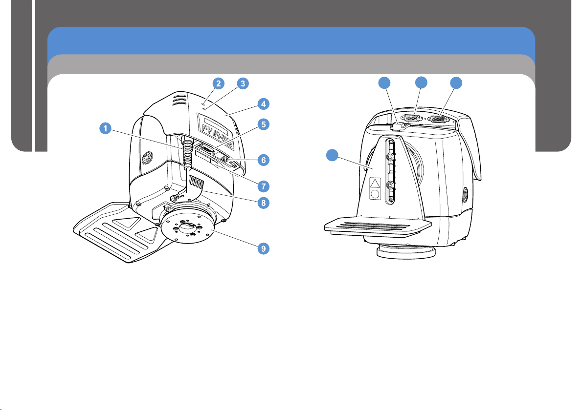
Components and Connections
Front View
Installation and Configuration Guide
1 . . . . . . . . . . . . . . . . . . . . . .
2 . . . . . . . . . . . . . . . . . . . . . . . . . . . . . . . . . . . . . . .
3. . . . . . . . . . . . . . . . . . . . . . . . . . . . . . . . . . . . .
4 . . . . . . . . . . . . . . . . . . . . . . . . . . . . . . . . . . . . . . .
5. . . . . . . . . . . . . . . . . . . . . . . . . . . . . . . . . . . . . .
6 . . . . . . . . . . . . . . . . . . . . . . . . . . . . . . . . . . . . .
7 . . . . . . . . . . . . . . . . . . . . . . . . . . . . . . . . . .
8 . . . . . . . . . . . . . . . . . . . . . . . . .
9 . . . . . . . . . . . . . . . . . . . . . . . . . . . . . . . . . . . Mounting plate
Power cable
Cable management bracket
with IEC connector
Genlock LED
Service port
Ethernet port
Network ID label
Data LED
Top cover
Rear View
11
10
10 . . . . . . . . . . . . . . . . . . . . . . . . . . . . . . . . . . . Camera cradle
11 . . . . . . . . . . . . . . . . . . . . . . . . . . . . . . . . . . . . . . . . . Tilt lock
12 . . . . . . . . . . . . . . . . . . . . . . . . . General purpose connector
13 . . . . . . . . . . . . . . . . . . . . . . . . . . . Lens interface connector
12
13
4
FHR-35 Pan and Tilt HeadRobotic
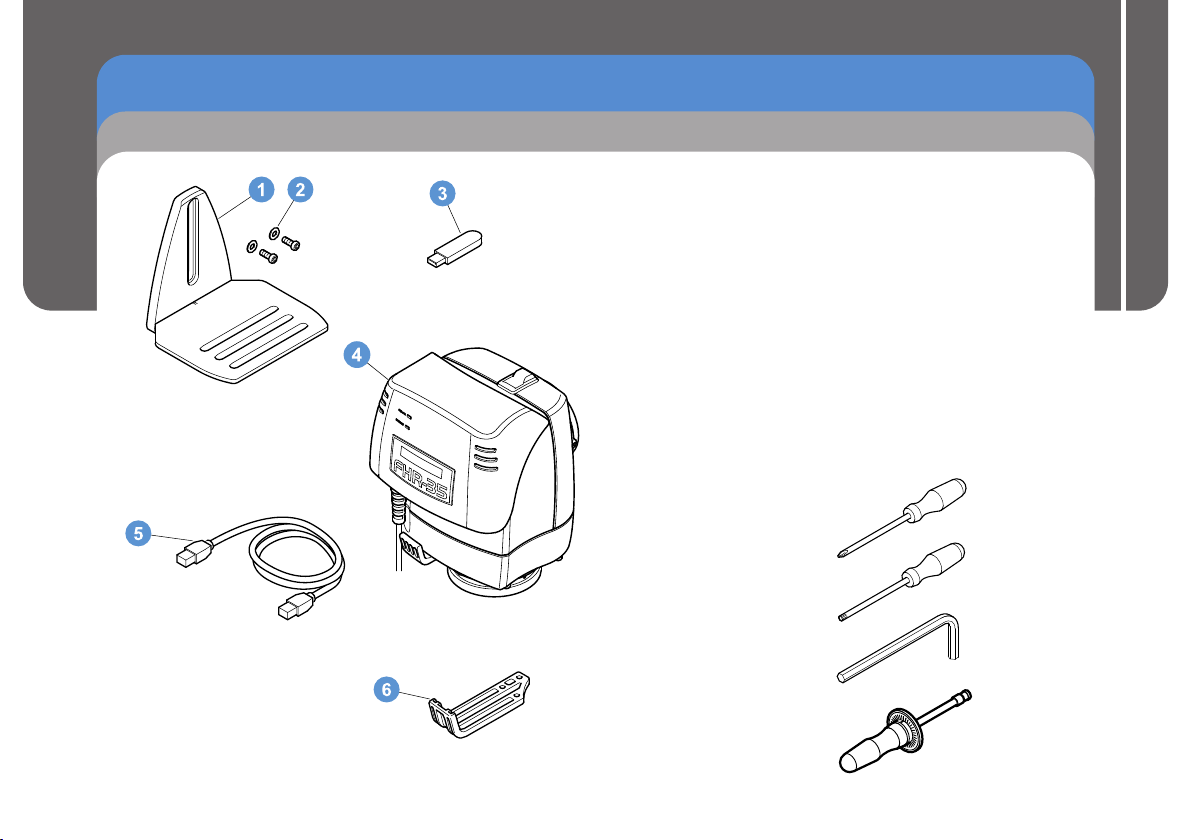
Installation
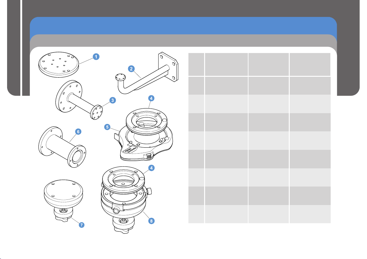
Box Contents and Tools Required
1 . . . . . . . . . . . . . . . . . . . . . . . . . . . . . . . . . . . . Camera cradle
2. . . . . . . . . . . . . . . . . . . . . . . . . . Cradle screws and washers
3 . . . . . . . . . . . . . . . . . . . . . . . . . . . . . . . . . . . . . . . . USB stick
4 . . . . . . . . . . . . . . . . . . . . . FHR-35 Robotic pan and tilt head
5 . . . . . . . . . . . . . . . . . . . . . . . . . . . . . . . . . . . .
6 . . . . . . . . . . . . . . . . . . . . . Large cable management bracket
NI . . . . . . . . . . . . . . . . . .
NI. . . . . . . . . . . . . . . . . . . . . . . . . . . . . . . . Quick Setup Guide
NI . . . . . . . . . . . . . . . . . . . . . . . . . . . . . . . . . . . . Cable ties x5
NI . . . . . 10-32 U x .625 in. pan head screws and washers x6
NI . . . . . . . . . . . . . M6 x 16 cap head screws and washers x4
NI . . . . . . . 3/8" BSW x 3/4" cap head screws and washers x2
NI = Not Illustrated
Tools required
®
Pozidriv PZ-1 screwdriver
®
Torx T10 screwdriver
Installation and Configuration Guide
Ethernet cable
Installation and Configuration Guide
4 mm Allen key
5 mm Allen key
5/16" Allen key
5/32" Allen key
Torque screwdriver
5
FHR-35 Pan and Tilt HeadRobotic
NO.
MOUNTING
SUPPORT OR
ADAPTOR
PART NO.
MOUNT
OPTION
1
VMA plate
AM-VMA-105
HD tripod
2
Wall mounting
bracket
AM-WBKT-102
Wall
3
Ceiling mounting
bracket
AM-CEIL-102
Ceiling
4
Adaptor with
Quickfix groove
V4096-1013
Pozi Loc tripod
HD tripod
5
Quickfix adaptor
3490-3
HD tripod
6
Radamec
adaptor column
196-728-0044
Ceiling
Pozi Loc tripod
7
150 mm bowl
adaptor
3104-3
Pozi Loc tripod
8
Quickfix 150 mm
bowl adaptor
3143-3
Pozi Loc tripod
Installation
Mounting Supports and Adaptors
Installation and Configuration Guide
6
FHR-35 Pan and Tilt HeadRobotic
Installation
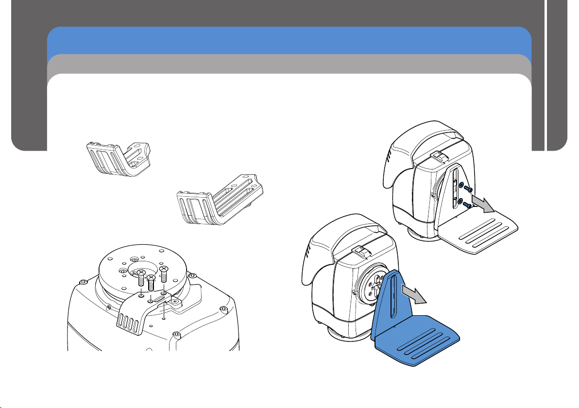
Cable Management Brackets
The FHR-35 is supplied with a cable management bracket fitted
to the base. Camera and head connecting cables can be neatly
secured to the bracket providing strain relief for the connectors.
Depending on the camera and head setup, the larger cable
management bracket can be fitted.
V4096-2075
Supplied fitted
to the head
V4096-2082
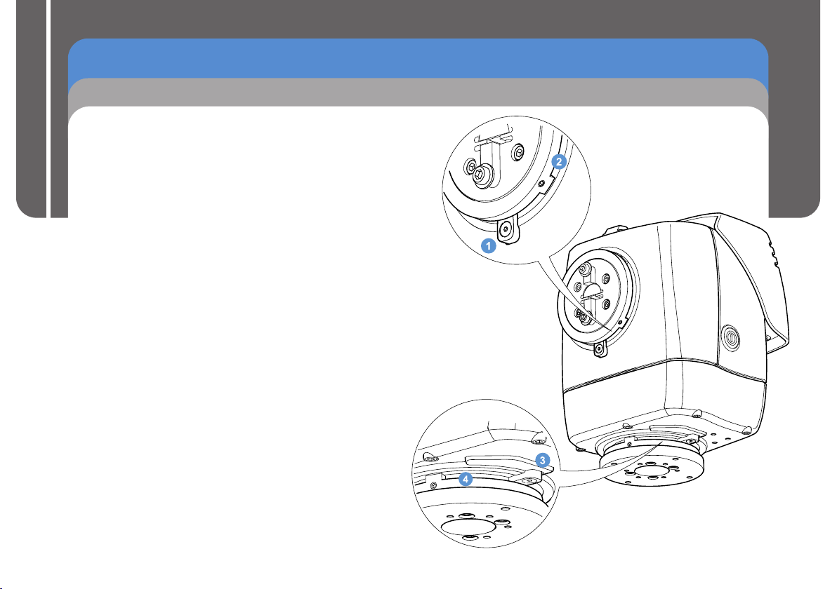
Removing the Camera Cradle
The first step in installing the head is to set the mechanical
hard stops to limit the movement of the head about the pan and
tilt axes. To set these limits, the camera cradle must be
removed.
Using a 4 mm Allen
1.
key,
remove the two
screws and washers
securing the camera
cradle.
2. Pull the camera
cradle away from
the mounting
tilt
plate.
Installation and Configuration Guide
7
FHR-35 Pan and Tilt HeadRobotic
Installation
Setting the Pan and Tilt Mechanical Hard Stops
The FHR-35 is fitted with adjustable
that safely restrict the range of movement about the pan and
tilt axes. The pan and tilt mountings have a fixed stop and
two adjustable stop rings that are locked at the required
maximum and minimum limits of movement.
Installation and Configuration Guide
Setting the pan and tilt mechanical hard stops ensures that:
- The head and payload cannot collide with any fixed objects
within the working robotic footprint of the head.
- The payload will not collide with the head or the mounting
bracket or support.
- Undesirable areas of the studio are kept out of shot.
When the mechanical hard stops are locked in position, the
head will not be able to drive beyond them. However, the
head is still able to drive and collide into the mechanical
hard stops. To prevent this, soft limits are programmed into
the head at points within the range of the mechanical hard
stops. This eliminates the risk of constant collision with the
mechanical hard stops, and also restricts the head’s
movement range further whenever necessary. See the
section Setting the Zero Position and Soft Limits for
more details.
mechanical hard stops
1.......................
2.......................
3......................
4......................
Tilt fixed stop
Tilt stop rings
Pan fixed stop
Pan stop rings
8
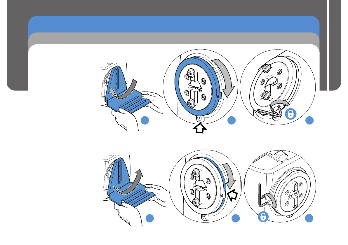
1.(a) Place the camera cradle
over the tilt mounting.
Move the tilt mounting in
a clockwise direction to
the required maximum
limit of movement.
(b) Remove the camera
cradle. Move the large
outer ring clockwise until
it rests on the fixed stop.
(c) Secure the grub screw
into position using a
2.5 mm Allen key. Tighten
the screw to a minimum
of 1.5 Nm (13.3 lbf-in.).
2.(a) Place the camera cradle
over the tilt mounting.
Move the tilt mounting in a
counterclockwise direction
to the required minimum
limit of movement.
(b) Remove the camera
cradle. Move the inner ring
clockwise until it rests on
the large outer ring stop.
(c) Secure the grub screw into
position using a 2.5 mm
Allen key. Tighten the
screw to a minimum of
1.5 Nm (13.3 lbf-in.).
FHR-35 Pan and Tilt HeadRobotic
Installation
Setting the Tilt Mechanical Hard Stops
Installation and Configuration Guide
a
a
a
b
b
c
c
9

FHR-35 Pan and Tilt HeadRobotic
Installation
Setting the Pan Mechanical Hard Stops
3.(a) Move the pan mounting
in a counterclockwise
direction to the required
minimum limit of
movement.
Installation and Configuration Guide
10
(b) Move the large outer ring
counterclockwise until it
rests on the fixed stop.
(c) Secure the grub screw
into position using a
2.5 mm Allen key. Tighten
the screw to a minimum
of 1.5 Nm (13.3 lbf-in.).
4.(a) Move the pan mounting
in a clockwise direction
to the required
maximum limit of
movement.
(b) Move the inner ring
counterclockwise until it
rests on the outer ring
stop.
(c) Secure the grub screw
into position using a
2.5 mm Allen key.
Tighten the screw to a
minimum of 1.5 Nm
(13.3 lbf-in.).
FHR-35 Robotic Pan and Tilt Head
a
a
b
b
c
c

FHR-35 Pan and Tilt HeadRobotic
Installation
Ceiling Mounting
The FHR-35 can be mounted to the ceiling using either a
column mount (part no. 196-728-0044) or a bracket (part no.
AM-CEIL-102). When mounting the head to a ceiling support,
the camera cradle must be inverted.
1. Refit the camera cradle to the tilt
mounting in an inverted orientation.
Using a 4 mm Allen key, secure in
position using the two screws and
washers.
2. Mount the head to the ceiling bracket or column.
Radamec Adaptor Column
(196-728-0044)
Using a 5 mm Allen key, attach
the head to the column mounting
using the four M6 cap head
screws and washers provided.
Ceiling Mounting Bracket
(AM-CEIL- )102
Using a 5/16" Allen key,
ttach the head to the ceiling
a
mounting bracket
six 10-32 cap head screws
and washers provided.
Installation and Configuration Guide
using the
11

FHR-35 Pan and Tilt HeadRobotic
Installation
Wall Mounting
The FHR-35 can be mounted to a wall using the wall mounting
bracket (part no. 196-728-0044). When mounting the head to
the wall, the cradle is fitted to the head in the standard position.
Installation and Configuration Guide
12
1. Fit the camera cradle to the tilt
mounting in the standard
positioning. Using a 4 mm
Allen key, secure in position
using the two screws and
washers.
User Guide
2. Using a 5/16" Allen key,
attach the head to the
wall mounting bracket
using the six 10-32 cap
head screws and
washers provided.

FHR-35 Pan and Tilt HeadRobotic
Pozi Loc Tripod Mounting Options
Installation
The FHR-35 can be mounted onto the following Pozi Loc tripods:
- Vinten two-stage aluminium EFP Pozi Loc tripod (part no. V4086-0001).
- Vinten two-stage carbon fibre EFP Pozi Loc tripod (part no. 3881-3).
When mounting the head to the tripod, the cradle is fitted to the head in
the standard position.
1. Fit the camera cradle to the tilt
mounting in the standard positioning.
Using a 4 mm Allen key, secure in
position using the two screws and
washers.
2. Mount the head to the Pozi Loc tripod using
one of the following three mounting options.
Radamec Adaptor Column
(196-728-0044)
Using a 5 mm Allen key, attach
the Radamec adaptor column
to the head using the four M6
screws and washers provided.
Mount onto the tripod using the
150 mm bowl adaptor.
Installation and Configuration Guide
13

FHR-35 Pan and Tilt HeadRobotic
Installation
Pozi Loc Tripod Mounting Options
Adaptor with Quickfix
Groove (V4096-1013)
Using a 5 mm Allen key, attach the
adaptor with Quickfix groove to the head
using the four M6 screws and washers
Installation and Configuration Guide
provided. Mount onto the tripod using
either the 150 mm bowl adaptor or the
Quickfix 150 mm bowl adaptor.
3104-3
150 mm bowl
adaptor
V4096-1013 Adaptor with
Quickfix groove
3143-3
bowl adaptor
Quickfix 150 mm
14

FHR-35 Pan and Tilt HeadRobotic
HD Tripod Mounting Options
Installation
The FHR-35 can be mounted onto the following heavy-duty
(HD) tripods:
- Vinten HDT-1 single-stage tripod (part no. 3901-3).
- Vinten HDT-2 two-stage tripod (part no. 3902-3).
When mounting the head to the tripod, the cradle is fitted to the
head in the standard position.
1. Fit the camera cradle to the tilt
mounting in the standard
positioning. Using a 4 mm Allen
key, secure in position using the
two screws and washers.
2. Mount the head to the HD tripod using one of
the following three mounting options.
Radamec Adaptor Column
(196-728-0044)
Using a 5 mm Allen key, attach the Radamec adaptor
column to the head using the four M6 screws and washers
provided. Attach the head and column onto the tripod
using the four bolts retained underneath the tripod mount.
Installation and Configuration Guide
15

FHR-35 Pan and Tilt HeadRobotic
Installation
HD Tripod Mounting Options
VMA Plate (AM-VMA-105)
Using a 5/16" Allen key, attach the
VMA plate to the head using the
six 10-32 screws provided. The
head can then be directly
Installation and Configuration Guide
mounted on the tripod.
Adaptor with Quickfix Groove (V4096-1013)
Using a 5 mm Allen key, attach the
adaptor with Quickfix groove to the
head using the four M6 screws and
washers provided. Mount onto the
tripod with a Quickfix adaptor.
16

FHR-35 Pan and Tilt HeadRobotic
Installation
Locking/Unlocking the Camera Cradle
Before installing or adjusting the camera or payload, the tilt lock
must be engaged. The tilt lock the camera
cradle in the horizontal position, to provide a stable platform
when making adjustments. The tilt lock is operated by a slider
button located on the top of the head.
Slide button back to
disengage tilt lock
Unlocked
Note: The tilt lock only operates when
the camera cradle is in the
horizontal position.
mechanism holds
Slide button forward
to engage tilt lock
Locked
1. Using a 4 mm Allen
key, loosen the two
screws securing the
camera cradle
enough to slide the
camera cradle to its
lowest position.
Secure in position
using the two screws.
Mounting the Camera
Installation and Configuration Guide
2. Carefully position
the camera onto
the cradle. Align the
mounting holes in
the bottom of the
camera with one of
the slots on the
cradle. Fit the two
screws and tighten
to secure the
camera in position.
17

FHR-35 Pan and Tilt HeadRobotic
Installation
Balancing the Head
The FHR-35 is designed to allow the camera and payload to
swing about its own Centre of Gravity (C of G), as opposed to
balancing with the use of springs or cams. The camera and
payload are mounted onto the camera cradle so the resulting
C of G aligns with the tilt-axis pivot point, providing true
balance.
Installation and Configuration Guide
When the head is correctly balanced, the robotic drives will
need the minimum amount of effort to move the head. A
correctly balanced head and payload can be set to any tilt
position and the head will maintain that position ‘hands off’.
Setting the Fore/Aft Balance
Ensure that the head and camera cradle are level before
balancing. The camera and payload should be fitted on the
cradle so that the load is balanced. This can be achieved by
moving the camera forwards (Fore) or backwards (Aft) on the
cradle.
CAUTION! Risk of damage to equipment. Be prepared
to prevent the camera and cradle from falling away
suddenly.
1. Engage the tilt lock. Loosen the bolts securing the camera to
the cradle just enough to be able to slide the camera and
payload backwards and forwards.
2. Hold and steady the camera cradle, and disengage the tilt
lock. Carefully release the camera cradle and observe how it
moves and where it stops.
If the camera cradle stops in a horizontal position (camera
pointing directly forward) the balance is correct.
If the camera cradle tilts forward (points downwards) then the
camera must be moved towards the rear of the head (aft).
18

FHR-35 Pan and Tilt HeadRobotic
Installation
Balancing the Head
If the camera cradle tilts backwards (points upward) then the
camera must be moved towards the front of the head (fore).
3. Reposition the camera as required on the camera cradle and
secure in position. The horizontal balance is correct when
the camera cradle comes to rest in a horizontal position.
4. Tighten the bolts securing the camera to the cradle and
recheck the horizontal balance. Readjust if necessary.
Note: If the camera has to be moved too far fore or aft to
balance the head, you can remove the camera cradle
base plate and refit it, using two screws, 50 mm further
in the required direction.
Adjusting the Centre of Gravity (C of G)
CAUTION! Risk of damage to equipment. Be prepared
to prevent the camera and camera cradle from falling
away suddenly.
Installation and Configuration Guide
1. Tilt the camera approximately 30° upward and release it.
If the camera stays in the same position when released, the
payload is properly balanced with the C of G on the tilt axis.
If the camera continues to move upwards after releasing the
camera cradle, the payload is mounted too high—lower the
camera cradle.
19

FHR-35 Pan and Tilt HeadRobotic
Installation
Balancing the Head
If the camera moves back towards the horizontal position when
released, the payload is mounted too low—raise the camera
cradle.
Installation and Configuration Guide
2. Tilt the camera cradle through positive and negative angles
of travel, checking that the head remains at the angle of tilt it
is set to, unsupported.
If the camera cradle angle falls or rises, repeat the alignment
procedure until balance is achieved.
3. After adjusting the C of G height it may be necessary to
check that the fore and aft balance remains satisfactory.
Readjust the position of the camera horizontally on the
camera cradle as required.
4. After balancing, exercise the head through both axes to
confirm that it operates smoothly.
Electrical Connections
CAUTION! Connect the head to the power source using
the attached power cable only. Ethernet cables must be
rated at Cat5e with screened RJ45 connectors.
WARNING! The IEC connector is the primary
disconnect device and must be accessible both during
and after installation of the product.
1. Connect the lens interface
cable to the lens interface
connector on the FHR-35.
2. Connect the
power cable
and the
Ethernet cable.
20

FHR-35 Pan and Tilt HeadRobotic
Installation
Cable Management
To ensure a safe and tidy installation, all of the cables connected
to the head can be secured neatly using the cable management
bracket. Depending on the type of head mounting, the cables can
also be secured to the tripod leg or mounting bracket using the
cable ties provided.
CAUTION! Leave sufficient slack in the cables between
the fixed mounting and the head for free and full range
of movement.
CAUTION! Cables must be secured to the cable
management bracket when head is mounted to a tripod.
Ceiling mounted
Powering Up
WARNING! Ensure that all personnel are clear from
the robotic equipment before powering up.
CAUTION! Disengage tilt lock before powering up.
Before powering up the head, ensure that all external cable
connections have been secured correctly.
To power up, press the power button located on the side of the
head. The head will not move when powered up, but zoom and
focus servos on the camera will take up their default positions
on analogue lenses.
The LEDs located at the rear of the head, indicate that data
communications (green LED) and a genlock signal (amber
LED) is present.
If the LEDs do not illuminate on power up, refer to the
Troubleshooting section of this manual.
Installation and Configuration Guide
Tripod or wall mount
21

FHR-35 Pan and Tilt HeadRobotic
ICE Tool
ICE Tool Installation
The USB stick provided with the FHR-35 contains a software
utility called ICE Tool. When installed onto a controller
, ICE Tool can be used to change configuration settings in
laptop
the head and setup the soft limits.
Installation and Configuration Guide
CAUTION! Risk of product damage. Soft limits must be
set inside the range set for the hard limits.
Installing ICE Tool
ICE Tool can be installed and run on either the Windows XP or
Windows 7 operating systems.
®
1. Insert the USB stick into the PC and view the contents.
2. Double-click on the ICE Tool Windows Installer icon to
launch ICE Tool Wizard Setup.
3. Click Next and tick to accept the license agreement.
4. Click Next and select a location for the program to install to
(the default location Program Files\Vinten Radamec\Ice
Tool\ is recommended).
5. Click Next for the software to automatically install.
6. Click Finish to exit the Install Wizard.
PC or
®
Using ICE Tool
1. To run the configuration software:
a) Double-click the ICE Tool icon to display the login
dialog box.
b) Select Customer Mode from the drop-down menu and
click Continue to display the ICE Tool window.
ICE Tool Login
Select User Mode
Customer Mode
Continue
Exit
2. Add the FHR-35 to the System tree:
a) Expand the Available Hosts tree
structure.
b) Expand the FHR35 folder, to list all
the available heads.
c) Double-click the Host ID of the
required head to load it onto the
System tree.
22

FHR-35 Pan and Tilt HeadRobotic
ICE Tool
Using ICE Tool
3. Display the Configuration window for the required head:
a) Expand the System tree structure.
b) Expand the FHR35 folder, to list all added heads.
c) Expand the Host ID of the required head.
d) Double-click the Head component to open the
Configuration window for the selected FHR-35 head.
Setting the Zero Position and Soft Limits
In the Configuration window, the zero point position and the
soft limits can be set or changed. The head can be manually
moved to the required minimum and maximum positions and
the values stored by the software. (in degrees)
If the head is mounted in an inaccessible location, such as
ceiling or wall mounted, where manually moving the head is not
possible, the pan and tilt position values can be entered into the
pan and tilt fields.
Setting the Zero Position
Setting a zero reference position before setting the soft limits
will make the configuration of the head easier. The zero
reference position for the tilt axis is, by default, when the
camera cradle is in the horizontal position (tilt lock engaged).
1. Manually move the head about the pan and tilt axes to
approximately the mid- points within the set hard limits.
range
2. Click the Set Zero button to store this position as zero
degrees in pan and tilt.
3. Click Apply to .send and store the settings in the head
Installation and Configuration Guide
23

FHR-35 Pan and Tilt HeadRobotic
ICE Tool
Soft Limits
Setting the pan and tilt soft limits
CAUTION! Risk of product damage. Soft limits must be
set inside the range set for the hard limits.
Installation and Configuration Guide
There are two methods for setting the soft limits, depending on
the accessibility of the mounting installation.
Accessible (or Manual) Mounting
1.
Move the pan mechanism to the required minimum
and click the Set Min button to store the value.
2. Move the pan mechanism to the required maximum position
and click the Set Max button.
epeat steps 1 and 2 to set the tilt axis minimum and
3.
R
maximum limits.
4.
Click Apply to send and store the settings in the head.
Inaccessible Mounting (Wall or Ceiling)
Enter a minimum
1.
Limits boxes and click the Set Min button to store the value.
Enter a maximum
2. soft limit value in the pan and tilt Max
Limits boxes and click the Set Max button.
Click Apply to send and store the settings in the head.
3.
soft limit value in the pan and tilt Min
position
Setting the zoom and focus soft limits
Minimum and maximum soft limits can also be set for the lens
focus and zoom. Units represent 0–100% of the full range for
each setting.
1. Set the lens to the required minimum zoom setting and click
the Set Min button to store the value.
2. Set the lens to the required maximum zoom setting and click
the Set Max button to store the value.
3. Repeat steps 1 and 2 to set limits for the focus.
4. Click Apply to send and store the settings in the head.
24

Configuration Settings
Key settings can also be changed in the Configuration
window:
Normalise Invert Axes
Select if the head is mounted upside down from
the ceiling. Pan and tilt axes are reversed to
give standard control on an inverted mount.
Enable Zoom Proportional
Select to enable the speed of pan and tilt
movement to be proportional to the zoom angle
(zoomed in slower and zoomed out faster).
Axes Invert
Pan Tilt
Zoom
Focus
Selecting a checkbox reverses
the direction of the axis when
controlled using a joystick.
FHR-35 Pan and Tilt HeadRobotic
ICE Tool
Installation and Configuration Guide
Lens Type
Select the applicable lens type
option from the drop-down menu.
25

FHR-35 Pan and Tilt HeadRobotic
Maintenance
Regular Checks
Routine Use
During use, check the following:
Once a month check the balance of the camera and
Ÿ
Installation and Configuration Guide
payload and adjust if necessary.
No further routine maintenance is required.
Cleaning
WARNING! Disconnect and isolate the product
from the power supply before cleaning.
We encourage regular cleaning of the product. During normal
use the only cleaning required should be a regular wipe over
with a lint-free cloth. External electrical connection ports should
only be cleaned with a vacuum cleaner.
Cover the head when not in use. Dirt accumulated during
storage or periods of non-use may be removed with a vacuum
cleaner.
26

Fault
Check
Action
Power supplied, but the camera cradle is
not moving.
Check that the tilt lock is disengaged.
See Locking/unlocking the Camera
Cradle
Head not operating.
Check that the power switch is ON.
See Powering up
Ensure that the power and Ethernet
cables are connected and secure.
See Electrical Connections
Check mains power supply to head.
Check that power is being supplied from
the pedestal, height drive or studio
supply.
Camera and payload moving too far on
the pan and/or tilt axis.
Check the setting of the hard and soft
limits.
See Setting the Pan and Tilt Hard
Limit Stops
and
Setting Pan and Tilt Soft Limits
Intermittent or no communications
Check Ethernet cable.
Check the Ethernet cable is CAT5E FTP.
If possible, try using another Ethernet
cable.
FHR-35 Pan and Tilt HeadRobotic
Troubleshooting
Installation and Configuration Guide
27

FHR-35 Pan and Tilt HeadRobotic
General Notices
Parts List
Mounting supports and adaptors
Vinten 4-bolt adaptor (with Quickfix® groove) . . . . V4096-1013
VMA plate . . . . . . . . . . . . . . . . . . . . . . . . . . . . . . . AM-VMA-105
Radamec adaptor column 196-728-0044
Installation and Configuration Guide
Autocam ceiling mounting bracket. . . . . . . . . . . . . AM-CEIL-102
Autocam wall mounting bracket . . . . . . . . . . . . . AM-WBKT-102
Vinten 4-bolt to 150 mm bowl adaptor . . . . . . . . . . . . . . . 3104-3
Vinten Quickfix 150 mm bowl adaptor . . . . . . . . . . . . . . 3143-3
Vinten HD Quickfix adaptor . . . . . . . . . . . . . . . . . . . . . . 3490-3
Vinten two-stage aluminium EFP Pozi Loc tripod V4086-0001
Vinten two-stage carbon fibre EFP Pozi Loc tripod 3881-3
Vinten HDT-1 single-stage tripod 3901-3
Vinten HDT-2 two-stage tripod 3902-3
®
. . . . . . . . . . . . . . . . . .
®
User-replaceable parts
Mounting kit
(incl. cable management brackets) . . . . . . . . . . . . . V4096-1905
. .
. . . . .
. . . . . . . . . . . . . . . . . . .
. . . . . . . . . . . . . . . . . . . . .
Specification
Physical data
Weight (with cradle) . . . . . . . . . . . . . . . . . . . . . . . . . 8 kg (18 lb)
Height . . . . . . . . . . . . . . . . . . . . . . . . . . . . . . 247.4 mm (9.7 in.)
Length . . . . . . . . . . . . . . . . . . . . . . . . . . . . . 323.5 mm (12.7 in.)
Width . . . . . . . . . . . . . . . . . . . . . . . . . . . . . . . 193.5 mm (7.6 in.)
Maximum payload . . . . . . . . . . . . . . . . . . . . . . . . . 16 kg (35 lb)
Operating data
Operating temperature range . . 0°C to +50°C (+32°F to +122°F)
Motor noise . . . . . . . . . . . . . . . . . . . . . . . . . . . . . . . . . . Minimal
Tilt range . . . . . . . . . . . . . . . . . . . . . . . . . . . . . . . . . . . . . . . ±90°
Pan range, max. (with mechanical end stops set) . . . . . . . 319°
Angular velocity (max) . . . . . . . . . . . . . . . . . . . . . . . . . . . . 60°/s
Angular acceleration (typical) . . . . . . . . . . . . . . . . . . . . . . 60°/s
Angular acceleration (peak) . . . . . . . . . . . . . . . . . . . . . . 120°/s
Accuracy . . . . . . . . . . . . . . . . . . . . . . . . . . . . . . . 60 arcseconds
Robotic operation . . . . . . . . . . . . . . . . . . . . . . . . . . . . . . . . . Full
Manual operation . . . . . . . . . . . . . . . . . . . . . . . . . . . . . . . . None
Electrical data
Power consumption . . . . . . . . . . . . . . . . . . . . . . . . . . . . . . 100W
Power input . . . . . . . . . . . Autoranging 100–240V AC, 50/60 Hz
2
2
28

FHR-35 Pan and Tilt HeadRobotic
General Notices
Compliance
Declaration of Conformity
Vitec Videocom
has been manufactured in accordance with BS EN
ISO 9001:2008 and is in compliance with the
essential requirements and other relevant provisions
of the Machinery Directive 2006/42/EC. A copy of the
Declaration of Conformity is available upon request.
Waste of Electrical and Electronic Equipment (WEEE)
Directive (2002/96/EC)
This symbol marked on the product or its packing
indicates that this product must not be disposed of
with general household waste. In some countries or
European Community regions, separate collection
systems have been set up to handle the recycling of
electrical and electronic waste products. By ensuring
this product is disposed of correctly you will help
prevent potentially negative consequences for the environment
and human health. The recycling of materials helps conserve
natural resources.
In countries outside the EU:
Dispose of this product at a collection point for the recycling of
electrical and electronic equipment according to your local
government regulations.
Visit our website for information on how to safely dispose of this
product and its packaging.
Limited declares that this product
RoHS Compliance Statement
Vitec Videocom Limited is compliant with the European Union
Directive 2002/95/EC (RoHS) that restricts the use of
hazardous substances in Electrical and Electronic Equipment.
The Restrictions of Hazardous Substances (RoHS directive).
Pollution Degree 2
This equipment is designed for operation in Pollution Degree 2
environments.
Installation and Configuration Guide
29

FHR-35 Pan and Tilt HeadRobotic
Pin No.
Description
Pin No.
Description
1
Not connected
14
Not connected
2
Aux GND
15
CCU TXD422
3
Aux +12V
16
CCU TXD232
4
Aux +12V
17
Not connected
5
Not connected
18
GP I/O 1
6
CCU RXD422
19
GND
7
CCU RXD232
20
Aux GND
8
GP I/O 3
21
Aux +12V
9
GP I/O 0
22
Not connected
10
GND23CCU TXD422
11
Aux GND
24
CCU RXD422
12
Aux GND
25
Not connected
13
Aux +12V
26
GP I/O 2
General Notices
Compliance
FCC Notice
This product complies with the limits for a Class B digital
Installation and Configuration Guide
device, pursuant to Part 15 of the FCC Rules. These limits are
designed to provide reasonable protection against harmful
interference in a residential installation. This equipment
generates, uses and can radiate radio frequency energy and, if
not installed and used in accordance with the instructions, may
cause harmful interference to radio or television reception,
which can be determined by turning the equipment off and on,
the user is encouraged to try to correct the interference by one
or more of the following measures:
Ÿ Reorient or relocate the receiving antenna
Ÿ Increase separation between the equipment and receiver
Ÿ Connect the equipment into an outlet on a circuit different
from that to which the receiver is connected
Ÿ Consult the dealer or an experienced radio/television
technician for assistance.
FCC Warning
Changes or modifications not expressly approved by the party
responsible for compliance could void the user’s authority to
operate the equipment.
FCC Declaration of Conformity
This product complies with Part 15 of the FCC Rules,
Operation is subject to the following two conditions:
(1) This product may not cause harmful interference.
(2) This product must accept any interference received,
including interference that may cause undesired
operations.
FHR-35
V4096-0001
General Purpose Connector
The General Purpose Connector can be used to connect a
Camera Control Unit (CCU) or for switching and powering other
camera accessories. The pin outs of the connector are given in
the following table.
CAUTION: Total power drawn from the 12V pins of this
connector must NOT exceed 30W.
30

FHR-35 Pan and Tilt HeadRobotic
End User License Agreement
General Notices
IMPORTANT PLEASE READ THE TERMS AND CONDITIONS
OF THIS LICENSE AGREEMENT CAREFULLY BEFORE
CONTINUING WITH THIS PROGRAM INSTALL:
Vitec Videocom
legal agreement between you (either an individual or a single
entity) and Ltd for the Ltd
software product(s) identified above which may include
associated software components, media, printed materials, and
‘online’ or electronic documentation (‘SOFTWARE PRODUCT’).
By installing, copying, or otherwise using the SOFTWARE
PRODUCT, you agree to be bound by the terms of this EULA.
This license agreement represents the entire agreement
concerning the program between you and Ltd,
(referred to as ‘licenser’), and it supersedes any prior proposal,
representation, or understanding between the parties. If you do
not agree to the terms of this EULA, do not install or use the
SOFTWARE PRODUCT. The SOFTWARE PRODUCT is
protected by copyright laws and international copyright treaties,
as well as other intellectual property laws and treaties. The
SOFTWARE PRODUCT is licensed, not sold.
1. GRANT OF LICENSE.
The SOFTWARE PRODUCT is licensed as follows:
to install and use copies of the SOFTWARE PRODUCT on your
computer running a validly licensed copy of the operating
system for which the SOFTWARE PRODUCT was designed
[e.g. Windows 95, Windows NT, Windows 98, Windows 2000,
Windows 2003, Windows XP, Windows ME, Windows Vista].
Ltd End-User License Agreement (‘EULA’) is a
Vitec Videocom Vitec Videocom
Vitec Videocom
Vitec Videocom(a) Installation and Use. Ltd grants you the right
b) Backup Copies. You may also make copies of the
SOFTWARE PRODUCT as may be necessary for backup and
archival purposes.
2. DESCRIPTION OF OTHER RIGHTS AND LIMITATIONS.
(a) Maintenance of Copyright Notices. You must not remove or
alter any copyright notices on any and all copies of the
SOFTWARE PRODUCT.
(b) Distribution. You may not distribute registered copies of the
SOFTWARE PRODUCT to third parties.
(c) Prohibition on Reverse Engineering, Decompilation, and
Disassembly. You may not reverse engineer, decompile, or
disassemble the SOFTWARE PRODUCT, except and only to
the extent that such activity is expressly permitted by applicable
law notwithstanding this limitation.
d) Rental. You may not rent, lease, or lend the SOFTWARE
PRODUCT.
(e) Support Services. Ltd may provide you with
support services related to the SOFTWARE PRODUCT
(“Support Services”). Any supplemental software code provided
to you as part of the Support Services shall be considered part
of the SOFTWARE PRODUCT and subject to the terms and
conditions of this EULA.
(f) Compliance with Applicable Laws.You must comply with all
applicable laws regarding use of the SOFTWARE PRODUCT.
Vitec Videocom
Installation and Configuration Guide
31

FHR-35 Pan and Tilt HeadRobotic
General Notices
End User License Agreement
3. TERMINATION
Without prejudice to any other rights, Vitec Videocom Ltd may
terminate this EULA if you fail to comply with the terms and
conditions of this EULA. In such event, you must destroy all
copies of the SOFTWARE PRODUCT in your possession.
Installation and Configuration Guide
4. COPYRIGHT
All title, including but not limited to copyrights, in and to the
SOFTWARE PRODUCT and any copies thereof are owned by
Vitec Videocom Ltd or its suppliers. All title and intellectual
property rights in and to the content which may be accessed
through use of the SOFTWARE PRODUCT is the property of
the respective content owner and may be protected by
applicable copyright or other intellectual property laws and
treaties. This EULA grants you no rights to use such content. All
rights not expressly granted are reserved by Vitec Videocom
Ltd.
5. NO WARRANTIES
Vitec Videocom Ltd expressly disclaims any warranty for the
SOFTWARE PRODUCT. The SOFTWARE PRODUCT is
provided ‘As Is’ without any express or implied warranty of any
kind, including but not limited to any warranties of
merchantability, noninfringement, or fitness of a particular
purpose. Vitec Videocom Ltd does not warrant or assume
responsibility for the accuracy or completeness of any
information, text, graphics, links or other items contained within
the SOFTWARE PRODUCT.
Vitec Videocom Ltd makes no warranties respecting any harm
that may be caused by the transmission of a computer virus,
worm, time bomb, logic bomb, or other such computer program.
Vitec Videocom Ltd further expressly disclaims any warranty or
representation to Authorized Users or to any third party.
6. LIMITATION OF LIABILITY
In no event shall Ltd be liable for any damages
(including, without limitation, lost profits, business interruption,
or lost information) rising out of ‘Authorized Users’ use of or
inability to use the SOFTWARE PRODUCT, even if
Videocom
damages. In no event will Ltd be liable for loss
of data or for indirect, special, incidental, consequential
(including lost profit), or other damages based in contract, tort
or otherwise. Ltd shall have no liability with
respect to the content of the SOFTWARE PRODUCT or any
part thereof, including but not limited to errors or omissions
contained therein, libel, infringements of rights of publicity,
privacy, trademark rights, business interruption, personal injury,
loss of privacy, moral rights or the disclosure of confidential
information.
Vitec Videocom
Vitec
Ltd has been advised of the possibility of such
Vitec Videocom
Vitec Videocom
32


Publication No. V4096-4980/4
Vinten Radamec
A Vitec Group brand
 Loading...