

Vinten Radamec CP4 User Manual

Operators Guide
CP4 Control Panel
CP4 Control Panel
Installation
EN
Part No. V4110-0001
V4110-0002
V4110-0003
www.vintenradamec.com

Copyright © 2012
All rights reserved.
Original Instructions: English
All rights reserved throughout the world. No part of this document may be stored in a retrieval system,
transmitted, copied or reproduced in any way, including, but not limited to, photocopy, photograph,
magnetic or other record without the prior agreement and permission in writing of the Vitec Group plc.
Disclaimer
The information contained in this manual is believed to be correct at the time of printing. Vitec Videocom
Ltd reserves the right to make changes to the information or specifications without obligation to notify any
person of such revision or changes. Changes will be incorporated in new versions of the publication.
We are making every effort to ensure that our manuals are updated on a regular basis to reflect changes
to product specifications and features. Should this manual not contain information on the core functionality
of your product, please let us know. You may be able to access the latest revision of this manual from our
website.
Vitec Videocom Ltd reserves the right to make changes to product design and functionality without
notification.
Trademarks
All product trademarks and registered trademarks are the property of The Vitec Group Plc.
All other trademarks and registered trademarks are the property of their respective companies.
Published by:
Vitec Videocom Ltd
Supports Technical Publications Department
Western Way, Bury St Edmunds
Suffolk IP33 3TB
United Kingdom
Email: technical.publications@vitecgroup.com

Contents
Safety. . . . . . . . . . . . . . . . . . . . . . . . . . . . . . . . . . . . . . . . . . . . . . . . . 2
About this Manual . . . . . . . . . . . . . . . . . . . . . . . . . . . . . . . . . . . . . . 3
Components and Connections . . . . . . . . . . . . . . . . . . . . . . . . . . . . 4
CP4 Front View . . . . . . . . . . . . . . . . . . . . . . . . . . . . . . . . . . . . . . 4
CP4 Rear View - Connections . . . . . . . . . . . . . . . . . . . . . . . . . . . 4
CP4 Base View . . . . . . . . . . . . . . . . . . . . . . . . . . . . . . . . . . . . . . 5
Box Contents . . . . . . . . . . . . . . . . . . . . . . . . . . . . . . . . . . . . . . . . 5
Installation . . . . . . . . . . . . . . . . . . . . . . . . . . . . . . . . . . . . . . . . . . . . 7
Mounting the CP4 . . . . . . . . . . . . . . . . . . . . . . . . . . . . . . . . . . . . 6
System Connections . . . . . . . . . . . . . . . . . . . . . . . . . . . . . . . . . . 7
Power Connections . . . . . . . . . . . . . . . . . . . . . . . . . . . . . . . . . . . 8
Powering Up . . . . . . . . . . . . . . . . . . . . . . . . . . . . . . . . . . . . . . . . 8
Touchscreen Interface . . . . . . . . . . . . . . . . . . . . . . . . . . . . . . . . . . . 9
Using the Touchscreen . . . . . . . . . . . . . . . . . . . . . . . . . . . . . . . . 9
Logging On . . . . . . . . . . . . . . . . . . . . . . . . . . . . . . . . . . . . . . . . . 9
Using the Onscreen Keyboard. . . . . . . . . . . . . . . . . . . . . . . . . . . 9
CP4 Home Screen . . . . . . . . . . . . . . . . . . . . . . . . . . . . . . . . . . . 10
Configuration . . . . . . . . . . . . . . . . . . . . . . . . . . . . . . . . . . . . . . . . . 11
CP4 Configuration . . . . . . . . . . . . . . . . . . . . . . . . . . . . . . . . . . . 11
Camera Heads Configuration . . . . . . . . . . . . . . . . . . . . . . . . . . 14
Software Upgrades . . . . . . . . . . . . . . . . . . . . . . . . . . . . . . . . . . 16
Operation . . . . . . . . . . . . . . . . . . . . . . . . . . . . . . . . . . . . . . . . . . . . 18
Operating Camera Heads . . . . . . . . . . . . . . . . . . . . . . . . . . . . . 18
Storing Shots . . . . . . . . . . . . . . . . . . . . . . . . . . . . . . . . . . . . . . . 20
Playing Shots . . . . . . . . . . . . . . . . . . . . . . . . . . . . . . . . . . . . . . . 20
Managing Shots. . . . . . . . . . . . . . . . . . . . . . . . . . . . . . . . . . . . . .21
Managing a Show . . . . . . . . . . . . . . . . . . . . . . . . . . . . . . . . . . . .22
Locking the CP4 . . . . . . . . . . . . . . . . . . . . . . . . . . . . . . . . . . . . .23
Battery indicator. . . . . . . . . . . . . . . . . . . . . . . . . . . . . . . . . . . . . .23
Powering Down . . . . . . . . . . . . . . . . . . . . . . . . . . . . . . . . . . . . . .23
Advanced Features . . . . . . . . . . . . . . . . . . . . . . . . . . . . . . . . . . . . .24
Advanced Feature Packages . . . . . . . . . . . . . . . . . . . . . . . . . . .24
Enabling a Licence Package . . . . . . . . . . . . . . . . . . . . . . . . . . . .24
Connecting Four Additional Heads . . . . . . . . . . . . . . . . . . . . . . .25
V4110-0003 Advanced Functions Licence . . . . . . . . . . . . . . . . .25
Troubleshooting. . . . . . . . . . . . . . . . . . . . . . . . . . . . . . . . . . . . . . . .28
Maintenance and Technical Specification . . . . . . . . . . . . . . . . . . .30
General Notices . . . . . . . . . . . . . . . . . . . . . . . . . . . . . . . . . . . . . . . .31
1
Safety
Important information on the safe installation and operation of this
product. Read this information before operating the product. For
your personal safety, read these instructions. Do not operate the
product if you do not understand how to use it safely. Save these
instructions for future reference.
Warning Symbols Used in these Instructions
Safety cautions are included in these instructions. These safety
instructions must be followed to avoid possible personal injury and
avoid possible damage to the product.
WARNING!
Where there is a risk of personal injury or injury to others,
comments appear supported by the warning triangle symbol.
Where there is a risk of damage to the product, associated
equipment, process or surroundings, comments appear
supported by the word ‘Caution’.
ELECTRIC SHOCK
Where there is a risk of electric shock, comments appear
supported by the hazardous voltage warning triangle.
Intended Use
The CP4 control panel is designed to remotely control robotic pan and
tilt heads and servo camera lenses. It is designed for use in TV studios
and other applications including houses of worship, conference
facilities, auditoriums, sports and OB truck applications, etc.
Health and Safety
WARNING! To avoid the risk of personal strain injuries
caused by repetitive motion, the operator should take regular
breaks when using the product.
Electrical Connection
CAUTION! This product must be connected to a power
supply of the same voltage (V) and current (A) as indicated
on the product. Refer to the Technical Specifications for the
product.
CAUTION! We recommend that you use the power supply
cable supplied with the product.
CAUTION! All connections to other devices must be made
using shielded cables.
CAUTION! Using alternative power sources will invalidate
the system EMC liability.
Mounting and Installation
WARNING! Always ensure that all power and auxiliary
communications cables are routed so that they do not
present any danger to personnel. Take care when routing
cables in areas where robotic equipment is in use.
Water, Moisture and Dust
WARNING! Protect the product from water, moisture and
dust. The presence of electricity near water can be
dangerous.
2

Safety and About this Manual
Operating Environment
CAUTION! The product should not be used outside the
operating temperature limits. Refer to the product Technical
Specifications for the operating limits for the product.
Cleaning
WARNING! Risk of electric shock. Always disconnect and
isolate the product from the power supply before cleaning.
CAUTION! Do not use solvent or oil-based cleaners,
abrasives or wire brushes. Only use detergent-based
cleaners.
Maintenance
WARNING! The fitting of non-approved parts and
accessories, or the carrying out of non-approved alterations
or servicing can be dangerous and could affect the safety of
the product. It may also invalidate the terms and conditions
of the product warranty.
Safety when Working with Robotic Equipment
In normal operation remote-controlled equipment can move suddenly
and without warning. Since audible warnings are not suitable for use
within the studio environment, it is recommended that only trained
personnel be allowed to work in the active areas where remotecontrolled heads and pedestals are located. The safe operating zone is
a minimum of 1 m (3 ft).
controls, viewfinder, prompter, etc.) to prevent inadvertent collisions or
injury to personnel.
If personnel are too close to a head or pedestal that is about to move,
the operator should prevent the motion from starting or stop the motion
if it has started.
We strongly recommend that the operator verifies visually that the
active area is clear of hazards and personnel, both before and during
remote operation.
About this Manual
The Vinten Radamec CP4 control panel has been designed to integrate
with Fusion FHR-35 robotic pan and tilt heads and compatible servo
camera lenses. This manual covers the installation, configuration and
operation of the CP4.
This manual also covers the application of additional licence packages
on the CP4 to provide the user with advanced features.
Safety Notes for Operators
Operators must familiarise themselves with the working footprint of the
robotic head, including all associated equipment (lens, zoom and focus
3
Components and Connections
1
2
3
4
5
6
7
8
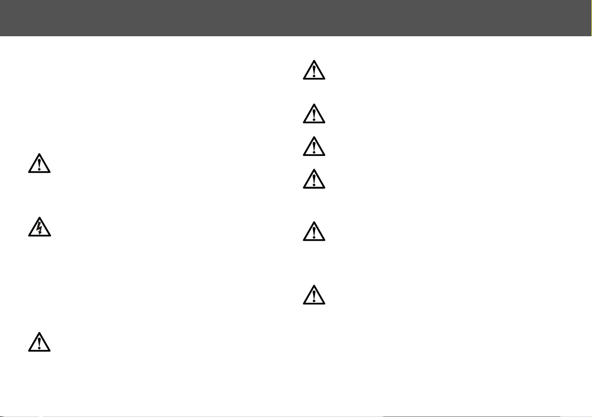
CP4 Front View
1 . . . . . . . . . . . . . . . . . . . . . . . . . . . . . . . . . . . . . . Touchscreen display
2 . . . . . . . . . . . . . . . . . . . . . . . . . . . . . . . . . . . . Power ON/OFF button
3 . . . . . . . . . . . . . . . . . . . . . . . . . . . . . . . . . . . . . . . . . . . . . . . .Joystick
4 . . . . . . . . . . . . . . . . . . . . . . . . . . . . . . . . . . . . . . .Zoom rocker switch
5 . . . . . . . . . . . . . . . . . . . . . . . . . . . . . . . . . . . . . . . . . . . . Focus wheel
CP4 Rear View - Connections
6 . . . . . . . . . . . . . . . . . . . . . . . . . . . . . . . . . . . . . . . . Power Connector
7 . . . . . . . . . . . . . . . . . . . . . . . . . . . . . . . . . . . . . . Ethernet connectors
8 . . . . . . . . . . . . . . . . . . . . . . . . . . . . . . . . . . . . . . . . . USB connectors
4
Components and Connections
9
10
9
9
9
1
2
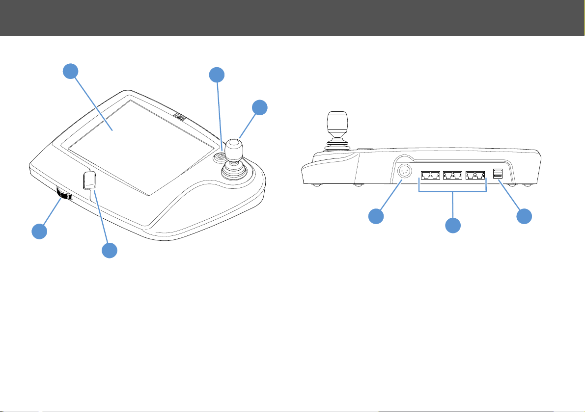
CP4 Base View
Box Contents
9 . . . . . . . . . . . . . . . . . . . . . . . . Rubber feet and panel mounting holes
10 . . . . . . . . . . . . . . . . . . . . . . . . . . . . . . Focus wheel drag adjustment
1 . . . . . . . . . . . . . . . . . . . . . . . . . . . . . . . . . . . . . . . . CP4 control panel
2 . . . . . . . . . . . . . . . . . . . . . . . . . . . . . . . . . . . . . . . . . . . . . AC adaptor
5
Installation
Note
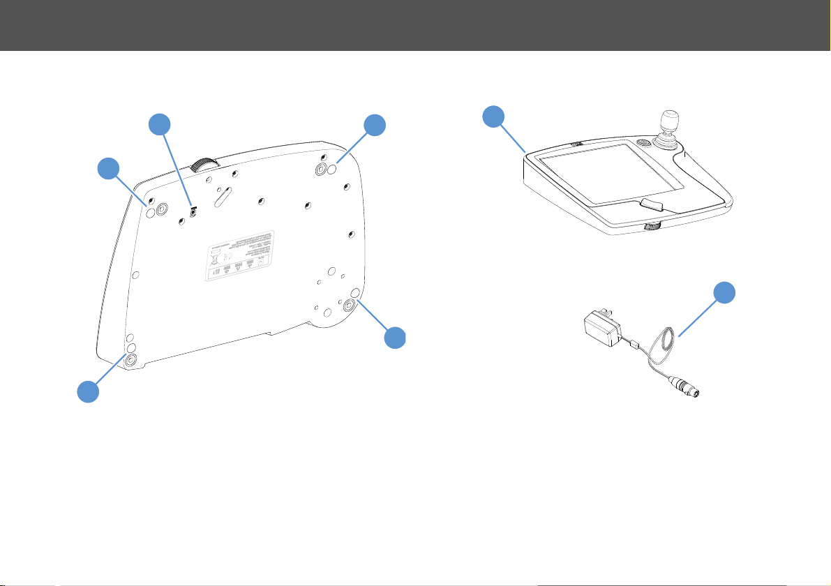
329 mm
240 mm
205 mm
65 mm
Mounting the CP4
The CP4 has four rubber feet fitted to the base so that it can be used
as a free standing unit on any level surface. However, the CP4 can also
be permanently fixed to a desk.
CAUTION! Risk of product damage. Only use M5 screws of
a length that will not screw into the panel mounting holes by
more than 5 mm. Do not overtighten the screws.
The focus wheel drag adjustment is inaccessible when
the CP4 has been permanently fixed to a desk. See
Adjusting the Focus Wheel on page 19.
1. Using a flat blade screwdriver, remove the four rubber feet from
the base of the panel.
2. Using the dimensions shown, accurately measure and mark the
locations of the hole centres onto the desk.
3. Drill 6 mm diameter holes through the work surface in the marked
positions. Fix the panel into position using four M5 screws of a
suitable length from underneath the desk into the panel mounting
holes.
6
Installation
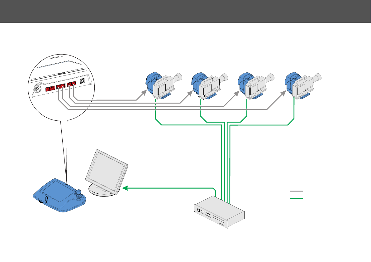
Video switcher unit
Preview
monitor
CP4 control panel
FHR-35 pan and tilt heads with cameras
Ethernet cabling
Video cabling
Key
System Connections
The diagram below shows a typical CP4 system installation with cameras mounted onto Fusion FHR-35 pan and tilt camera heads. A preview monitor
is required to view the video signal from the camera currently selected on the CP4.
7
Installation
OR
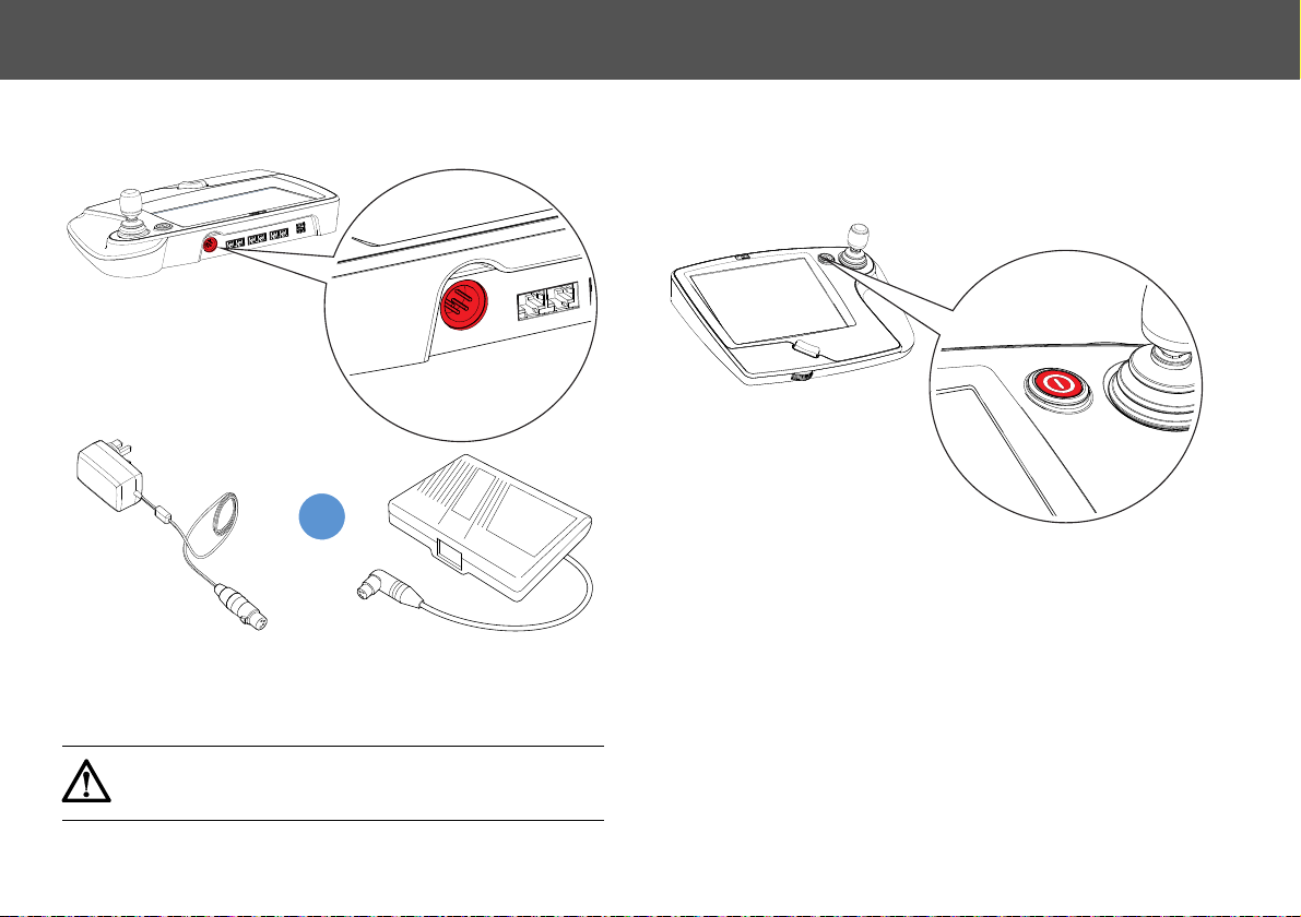
Power Connections
Connect the CP4 to the AC supply using the AC adaptor provided.
The CP4 can also be powered using a compatible 12 volt external
battery pack. The Anton Bauer battery gold mount (product no. V4110-
1002) can be used with the CP4. Using an Anton Bauer battery pack
provides battery life indication on the panel display.
Powering Up
Before powering up, ensure that all external cable connections have
been secured correctly.
To power up, press the on/off power switch.
The power button will illuminate and the boot-up screen appears. From
initial power up, the CP4 takes approximately 20 seconds to become
fully operational.
CAUTION! When powering the CP4 from a battery pack,
always ensure that there is sufficient charge to avoid power
failure during a show or the loss of unsaved data.
8
Touchscreen Interface
1234567890-
qwe r t yu i op
Caps a s d f g h j k l Clear
Shift z x c v b h
m
. ‘ Enter
Clear
Enter
Using the Touchscreen
The CP4 user interface consists of a touchscreen which is used to
configure and operate the panel. The touchscreen is sensitive and only
requires light finger pressure to register a response.
Single tap
Tap and hold
Tap, hold
and drag
Momentarily tapping the screen selects
an item or opens a menu.
Tapping and holding on some items
opens an additional configuration menu.
Use on scroll bars and setting controls in
some screens.
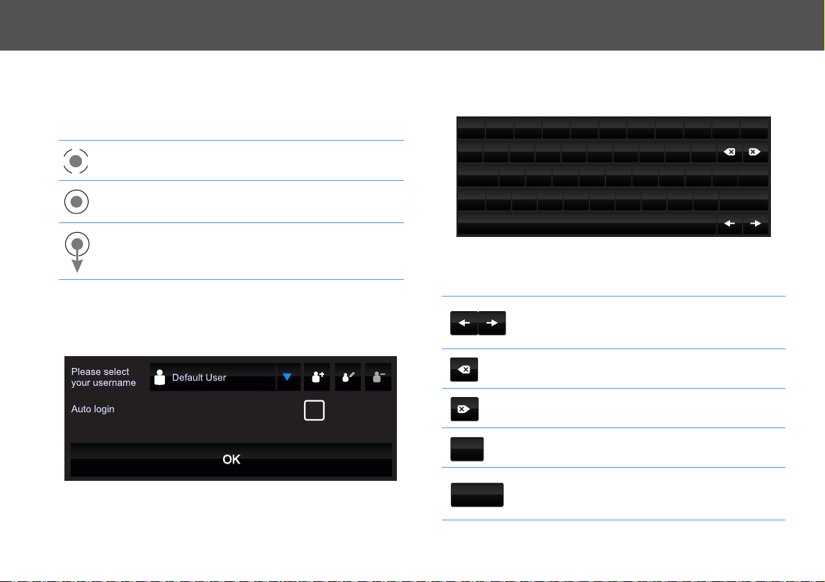
Logging On
When the CP4 is powered up for the first time, the Login to Panel
window appears with Default User selected as the user name.
Tap OK to log into the CP4 Home Screen.
Using the Onscreen Keyboard
The CP4 has an onscreen keyboard utility to input and edit stored
information.
The keyboard uses the Qwerty layout with additional special function
keys:
Use the left and right arrow keys to
Arrow keys
Back delete
key
Forward
delete key
Clear key
Enter key
move the cursor insertion point
within an existing text field.
Use to delete characters to the left of
the cursor insertion point.
Use to delete characters to the right
of the cursor insertion point.
Use to clear all contents in the text
field.
Use to confirm the current contents
of the text field and close the
keyboard.
9
 Loading...