


Ci Box ICE Interface
Installation and Configuration Guide
Ci Box ICE Interface
Installation
EN
Part No. V4115-0001
V4115-0002
www.vintenradamec.com

Copyright © 2013
All rights reserved.
Original Instructions: English
All rights reserved throughout the world. No part of this document may be stored in a retrieval system,
transmitted, copied or reproduced in any way, including, but not limited to, photocopy, photograph,
magnetic or other record without the prior agreement and permission in writing of the Vitec Group plc.
Disclaimer
The information contained in this manual is believed to be correct at the time of printing. Vitec Videocom
Ltd reserves the right to make changes to the information or specifications without obligation to notify any
person of such revision or changes. Changes will be incorporated in new versions of the publication.
We are making every effort to ensure that our manuals are updated on a regular basis to reflect changes
to product specifications and features. Should this manual not contain information on the core functionality
of your product, please let us know. You may be able to access the latest revision of this manual from our
website.
Vitec Videocom Ltd reserves the right to make changes to product design and functionality without
notification.
Trademarks
All product trademarks and registered trademarks are the property of The Vitec Group Plc.
All other trademarks and registered trademarks are the property of their respective companies.
Published by:
Vitec Videocom Ltd
Supports Technical Publications Department
Western Way, Bury St Edmunds
Suffolk IP33 3TB
United Kingdom
Email: technical.publications@vitecgroup.com

Safety. . . . . . . . . . . . . . . . . . . . . . . . . . . . . . . . . . . . . . . . . . . . . . . . . . . . . . . . . . . . . . . . . . . . . . . . . 2
About this Manual . . . . . . . . . . . . . . . . . . . . . . . . . . . . . . . . . . . . . . . . . . . . . . . . . . . . . . . . . . . . . . 3
Compatibility. . . . . . . . . . . . . . . . . . . . . . . . . . . . . . . . . . . . . . . . . . . . . . . . . . . . . . . . . . . . . . . . . 3
Components and Connections . . . . . . . . . . . . . . . . . . . . . . . . . . . . . . . . . . . . . . . . . . . . . . . . . . . . 4
Ci Box Front View . . . . . . . . . . . . . . . . . . . . . . . . . . . . . . . . . . . . . . . . . . . . . . . . . . . . . . . . . . . . 4
Ci Box Rear and Underside View. . . . . . . . . . . . . . . . . . . . . . . . . . . . . . . . . . . . . . . . . . . . . . . . . 4
Box Contents . . . . . . . . . . . . . . . . . . . . . . . . . . . . . . . . . . . . . . . . . . . . . . . . . . . . . . . . . . . . . . . . 5
Installation. . . . . . . . . . . . . . . . . . . . . . . . . . . . . . . . . . . . . . . . . . . . . . . . . . . . . . . . . . . . . . . . . . . . . 6
Mounting the Ci Box. . . . . . . . . . . . . . . . . . . . . . . . . . . . . . . . . . . . . . . . . . . . . . . . . . . . . . . . . . . 6
Fitting the Rubber Feet . . . . . . . . . . . . . . . . . . . . . . . . . . . . . . . . . . . . . . . . . . . . . . . . . . . . . 6
Fixing Kit Mounting . . . . . . . . . . . . . . . . . . . . . . . . . . . . . . . . . . . . . . . . . . . . . . . . . . . . . . . . 7
Rack Shelf Kit Mounting . . . . . . . . . . . . . . . . . . . . . . . . . . . . . . . . . . . . . . . . . . . . . . . . . . . . 8
System Connections . . . . . . . . . . . . . . . . . . . . . . . . . . . . . . . . . . . . . . . . . . . . . . . . . . . . . . . . . 10
Front Panel Data Connections. . . . . . . . . . . . . . . . . . . . . . . . . . . . . . . . . . . . . . . . . . . . . . . 10
Rear Panel Data Connections . . . . . . . . . . . . . . . . . . . . . . . . . . . . . . . . . . . . . . . . . . . . . . . 11
Power Connections . . . . . . . . . . . . . . . . . . . . . . . . . . . . . . . . . . . . . . . . . . . . . . . . . . . . . . . . . . 11
Powering Up. . . . . . . . . . . . . . . . . . . . . . . . . . . . . . . . . . . . . . . . . . . . . . . . . . . . . . . . . . . . . . . . 11
Data Indication . . . . . . . . . . . . . . . . . . . . . . . . . . . . . . . . . . . . . . . . . . . . . . . . . . . . . . . . . . . . . . 12
Configuration . . . . . . . . . . . . . . . . . . . . . . . . . . . . . . . . . . . . . . . . . . . . . . . . . . . . . . . . . . . . . . . . . 12
Adjusting the Modem Signal Level (Ci-1 Only) . . . . . . . . . . . . . . . . . . . . . . . . . . . . . . . . . . . . . 12
Changing the Data Baud Rate (Ci-1 Only). . . . . . . . . . . . . . . . . . . . . . . . . . . . . . . . . . . . . . . . . 13
Maintenance . . . . . . . . . . . . . . . . . . . . . . . . . . . . . . . . . . . . . . . . . . . . . . . . . . . . . . . . . . . . . . . . . . 13
Troubleshooting . . . . . . . . . . . . . . . . . . . . . . . . . . . . . . . . . . . . . . . . . . . . . . . . . . . . . . . . . . . . . . . 14
Technical Specification and General Notices . . . . . . . . . . . . . . . . . . . . . . . . . . . . . . . . . . . . . . . 15
Contents
1
Safety
Important information on the safe installation and operation of
this product. Read this information before operating the product.
For your personal safety, read these instructions. Do not operate
the product if you do not understand how to use it safely. Save
these instructions for future reference.
Warning Symbols Used in these Instructions
Safety cautions are included in these instructions. These safety
instructions must be followed to avoid possible personal injury and
avoid possible damage to the product.
WARNING!
Where there is a risk of personal injury or injury to others,
comments appear supported by the warning triangle symbol.
Where there is a risk of damage to the product, associated
equipment, process or surroundings, comments appear
supported by the word ‘Caution’.
ELECTRIC SHOCK
Where there is a risk of electric shock, comments appear
supported by the hazardous voltage warning triangle.
Intended Use
The Vinten Radamec Ci series of interfaces are intended for use in TV
studios, houses of worship, parliamentary assemblies, conference
facilities or similar environments. They are intended for installation by
competent broadcast professionals to assist with the integration of
third-party equipment with Vinten Radamec control systems.
Electrical Connection
CAUTION! This product must be connected to a power
supply of the same voltage (V) and current (A) as indicated
on the product. Refer to the technical specifications for the
product.
CAUTION! We recommend that you use the power supply
cable supplied with the product.
CAUTION! All connections to other devices must be made
using shielded cables.
CAUTION! Using alternative power sources will invalidate
the system EMC liability.
Mounting and Installation
WARNING! Always ensure that all power and auxiliary
communications cables are routed so that they do not
present any danger to personnel. Take care when routing
cables in areas where robotic equipment is in use.
Water, Moisture and Dust
WARNING! Protect the product from water, moisture and
dust. The presence of electricity near water can be
dangerous.
2
Safety and About this Manual
Operating Environment
CAUTION! The product should not be used outside the
operating temperature limits. Refer to the product technical
specifications for the operating limits for the product.
Cleaning
WARNING! Risk of electric shock. Always disconnect and
isolate the product from the power supply before cleaning.
CAUTION! Do not use solvent or oil-based cleaners,
abrasives or wire brushes. Only use detergent-based
cleaners.
Maintenance
WARNING! The fitting of non-approved parts and
accessories, or the carrying out of non-approved alterations
or servicing can be dangerous and could affect the safety of
the product. It may also invalidate the terms and conditions
of the product warranty.
About this Manual
The range of Vinten Radamec Ci box ICE interfaces have been
designed to assist in the integration of third party compatible broadcast
products/equipment to Vinten Radamec control systems. This manual
covers the installation and configuration of a Ci box, and its connections
with compatible products and studio equipment.
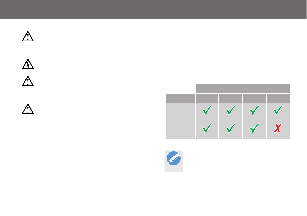
Compatibility
The following table describes the key differences between the Ci boxes
available:
Interfaces
Ci Box Ethernet RS232 RS422 Modem
Ci-1
V4115-0001
Ci-2
V4115-0002
The Ci-1 box is used for illustrative purposes throughout
this manual.
Note
3
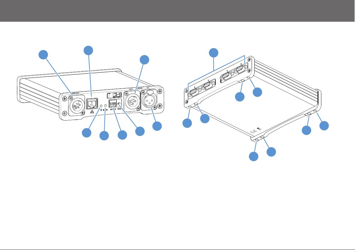
Components and Connections
Ci Box Front View
1
2
3
4
8
1 . . . . . . . . . . . . . . . . . . . . . . . . . . . . . . . . . . . . . . . . . Power connector
2 . . . . . . . . . . . . . . . . . . . . . . . . . . . . . . . . . . . . . . . Ethernet connector
3 . . . . . . . . . . . . . . . . . . . . . . . . . . . . . . . . . . . . . . Modem output port*
4 . . . . . . . . . . . . . . . . . . . . . . . . . . . . . . . . . . . . . . . Modem input port*
5 . . . . . . . . . . . . . . . . . . . . . . . . . . . . . . . . . . . . . . Modem gain control*
6 . . . . . . . . . . . . . . . . . . . . . . . . . . . . . . . Baud rate selection switches*
7 . . . . . . . . . . . . . . . . . . . . . . . . . . . . . . . . . . . . . . . Data indicator LED
8 . . . . . . . . . . . . . . . . . . . . . . . . . . . . . . . . . . . . . . Power indicator LED
7
5
6
Ci Box Rear and Underside View
9
10
11
10
9 . . . . . . . . . . . . . . . . . . . . . . . . . . . . . . . . . . . . . .Serial Connectors x4
10 . . . . . . . . . . . . . . . . . . . . . . . . . . . . . . . . . . . . . . . . . Mounting holes
11 . . . . . . . . . . . . . . . . . . . . . . . . . . . . . . .Rubber feet mounting points
* Ci-1 box only.
11
10
11
11
10
4

Components and Connections
Box Contents Optional Accessories
6
1
2
V4115-1900
x 8
x 6
3
1 . . . . . . . . . . . . . . . . . . . . . . . . . . . . . . . . . . . . . . Ci box ICE interface
5
x 4
x 2
4
x 2
x 4
2 . . . . . . . . . . . . . . . . . . . . . . . . . . . . . . . . . . . . . . . . . . . . . AC adaptor
3 . . . . . . . . . . . . . . . . . . . . . . . . . . . . . . . . . . . . . . . Ethernet cable, 2 m
4 . . . . . . . . . . . . . . . . . . . . . . . . . . . . . . . . . . . . . . . . . . Ci box fixing kit
5 . . . . . . . . . . . . . . . . . . . . . . . . . . . . . . . . . . . . . . . . . . . . . Rubber feet
6 . . . . . . . . . . . . . . . . . . . . . . . . . . . . . . . . . . . . . . . Ci box rack shelf kit
5

Installation
Tools Required
Pozidriv PZ-1
screwdriver.
Potentiometer adjuster
or small flat blade
screwdriver.
OR
Mounting the Ci Box
The Ci box is supplied with four rubber feet which can be fitted to the
base so that it can be placed on any level surface. However, the Ci box
can also be attached to equipment in an installation using one of the
following mounting kits:
Mounting Kit Part No. Use
Ci box fixing
kit
Ci box Rack
shelf kit
V4115-1901
(Included)
V4115-1900
To mount the Ci-box onto studio
equipment such as a tripod leg
To permanently install the Cibox in a 19-inch rack
Fitting the Rubber Feet
The supplied rubber feet should always be fitted to the
base of the Ci box unless it is to be mounted using the rack
Note
1.
shelf kit.
Peel the self adhesive backing
from the rubber foot.
2. Press the rubber foot firmly into place in one of the mounting point
recesses on the base of the Ci box. Fit the other three rubber feet
using the same procedure.
6

Installation
Fixing Kit Mounting
1.
Fit the screws through the holes in the Velcro straps, with washers
either side of the straps.
x2
2. Attach the straps to two of the mounting holes on the Ci box.
3. Wrap the Velcro straps around the equipment the Ci box is being
attached to, such as a tripod leg.
7

Installation
4. Continue to wrap and overlap the whole of the Velcro straps
around the equipment and the Ci box so that the Velcro can
secure it tightly in position.
Rack Shelf Kit Mounting
Two Ci boxes can be mounted to the rack shelf in the following
configurations:
Front
mounted
OR
Rear
mounted
1. Choose the mounting configuration option which best suits the
requirements of the rack installation.
8

Installation
2. Place the Ci box on a level surface with the underside facing
upwards in the required orientation.
3. Place the rack mount shelf over the Ci box as shown below.
Carefully align the four screw holes in the box with the required
mounting position holes in the shelf.
4. Secure the Ci box to the rack mount shelf using four of the M3
countersink screws provided.
5. Turn the rack mount shelf back over and install it into the 19 inch
rack. An additional Ci box can be fitted to the shelf in the spare
position using the same procedure used in steps 1 to 4.
9

Installation
6. Fit the supplied cable clips to the back edge of the rack mount
shelf to secure any connecting cables used in the installation.
System Connections
Front Panel Data Connections
ICE Ethernet
control data
connection
Modem
output data
connection*
Modem
input data
connection*
10
* Ci-1 box only.
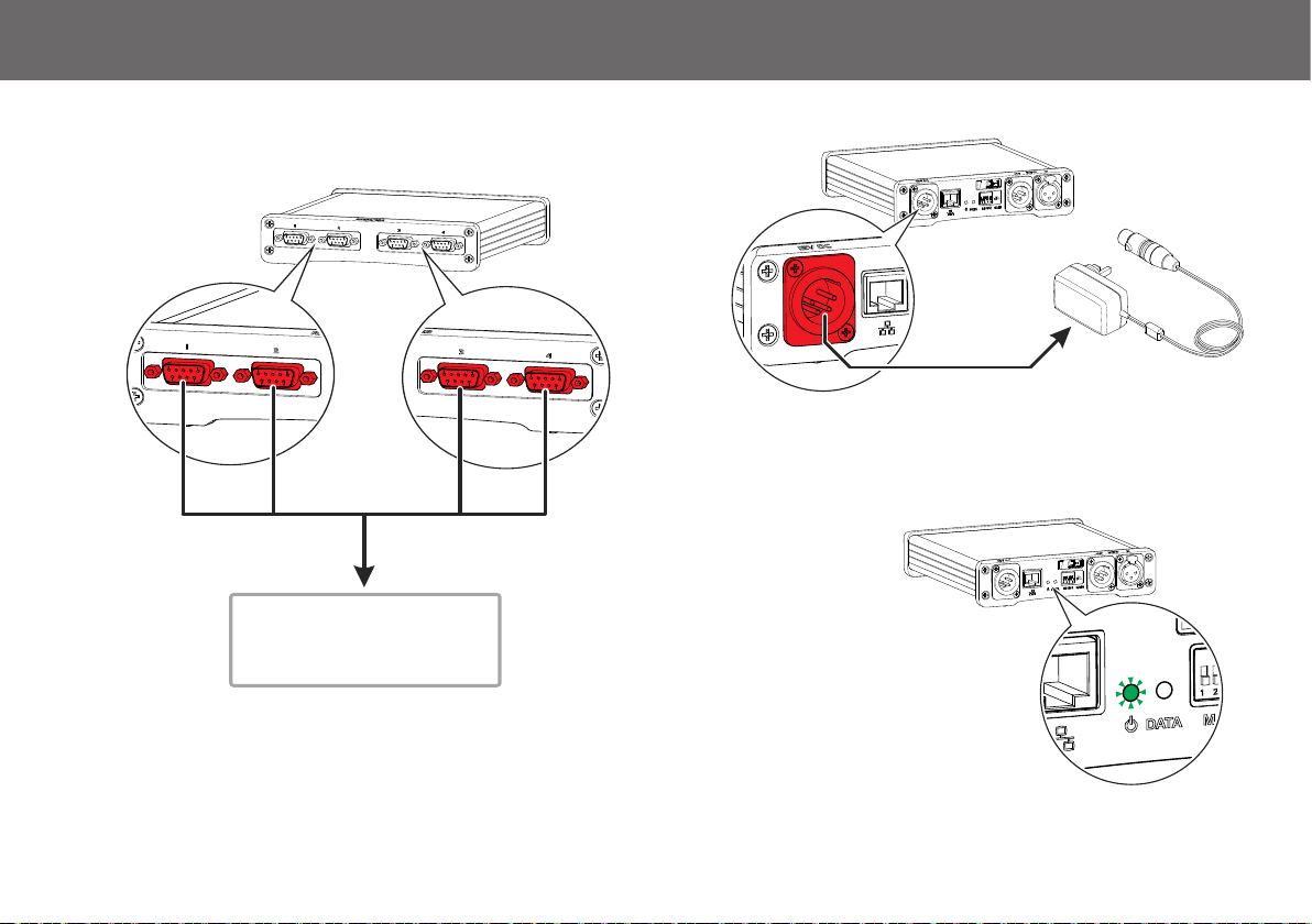
Rear Panel Data Connections Power Connections
Powering Up
Before powering up, ensure that all external cable connections have
been secured correctly.
To power up, connect
the AC adaptor to the
power supply. The
RS232/422 serial data
connections to compatible
robotic heads and camera
control units
power indicator LED
on the Ci box will
illuminate.
Installation
11

Configuration
Data Indication
The data indication LED shows the current system communication
status of the Ci box.
LED Illumination Colour Status
None No data communication present
Flashing
Green
Modem data communication is
present
Adjusting the Modem Signal Level (Ci-1 Only)
In installations where long cable runs are used for the modem data to
control heads, it may be necessary to boost the signal level to
compensate for distance.
1. Using a potentiometer adjuster or a small screw driver, turn the
modem gain control clockwise to increase the output signal level.
2. Check that the connected heads can be reliably controlled. If
necessary, use the modem gain control to increase the output
signal level further.
12
Note
If the Ci-1 is subsequently used in an installation with
very short cable runs, turn the modem dB adjuster
fully anti-clockwise.

Maintenance
Changing the Data Baud Rate (Ci-1 Only)
Depending on the requirements of the installation, the data baud rates
of the modem input and output channels on the Ci-1 can be
independently changed with the mode selection switches. The
following data baud rates are available for selection:
Output
Settings
Baud Use 1 2 3 4
For the most responsive control of
4800
heads, although this rate can be
unreliable over longer cable runs.
2400 For longer cable runs
1200 For phone line or RF transmissions
Set the numbered
switches on the Ci-1
to change the baud
rates.
Input
Settings
Routine Maintenance
The Ci box requires minimal routine maintenance, apart from checking
the connections and overall operation periodically.
Routine checks
During use, check the following:
• Check cables for signs of wear or damage. Replace as necessary.
• Check that all cables are connected properly.
Cleaning
During normal use the only cleaning required should be a regular wipe
over with a dry, lint-free cloth. Dirt accumulated during storage or
periods of disuse may be removed with a vacuum cleaner. Particular
attention should be paid to all connection ports.
13

Troubleshooting
Fault Check Comments
The Ci box is not
powering up.
Intermittent or no
communication
with connected
camera equipment.
Check that the AC adaptor is connected and secured.
If the Ci box is being powered by a battery pack, ensure that the battery
is fully charged.
Check that AC power is being supplied to the AC adaptor.
Check that the camera equipment is receiving power and is switched on.
Check that any data cables between the Ci box and the camera
equipment are correctly connected and secured.
If long modem cable runs are being used, try boosting the signal level
supplied from the Ci-1.
Check that the modem baud rate is set correctly for the current
installation.
See the section Rear Panel Data
Connections on page 11
See the section Fit the supplied cable clips
to the back edge of the rack mount shelf
to secure any connecting cables used in
the installation. on page 10
See the section Data Indication on page 12
See the section Changing the Data Baud
Rate (Ci-1 Only) on page 12
14

Technical Specification and General Notices
Technical Specification
Physical Data
Weight . . . . . . . . . . . . . . . . . . . . . . . . . . . . . . . . . . . . . . . 807 g (1.8 lb)
Height (without feet attached) . . . . . . . . . . . . . . . . . .40.4 mm (1.6 in.)
Length . . . . . . . . . . . . . . . . . . . . . . . . . . . . . . . . . . .181.8 mm (7.2 in.)
Width . . . . . . . . . . . . . . . . . . . . . . . . . . . . . . . . . . . . 168.5 mm (6.6 in.)
Environmental Data
Operating temperature range . . . . . . . . 0°C to +50°C (32°F to +122°F)
Electrical Data
Power input . . . . . . . . . . . . . . . . . . . . . . . . . . . . . . . .10.2 to 14.2V DC
Power consumption . . . . . . . . . . . . . . . . . . . . . . . . . . . . . . . . . . 1.32W
System fuse rating . . . . . . . . . . . . . . . . . . . . . . . . . . . . . . . . . . 500 mA
Electrical interfaces . . . . . . . . . . . . . . . . Serial data, modem, Ethernet
Data Specification
Supported protocols . . . . . . . . . . . . . . . . . . . . . . . . . . . RS232, RS422
Technical specifications are subject to change without notice.
FCC Certification
Ci Box ICE Interface
V4115-0001
V4115-0002
FCC Notice
This product complies with the limits for a Class B digital device,
pursuant to Part 15 of the FCC Rules. These limits are designed to
provide reasonable protection against harmful interference in a
residential installation. This equipment generates, uses and can radiate
radio frequency energy and, if not installed and used in accordance
with the instructions, may cause harmful interference to radio or
television reception, which can be determined by turning the equipment
off and on. The user is encouraged to try to correct the interference by
one or more of the following measures:
• Reorient or relocate the receiving antenna.
• Increase the separation between the equipment and receiver.
• Connect the equipment into an outlet on a circuit different from that
to which the receiver is connected.
• Consult the dealer or an experienced radio/television technician
for assistance.
FCC Warning
Changes or modifications not expressly approved by the party
responsible for compliance could void the user’s authority to operate
the equipment.
15

General Notices
FCC Declaration of Conformity
This product complies with Part 15 of the FCC Rules. Operation is
subject to the following two conditions:
1.This product may not cause harmful interference.
2.This product must accept any interference received, including
interference that may cause undesired operations.
Declaration of Conformity
Vitec Videocom Limited declares that this product has been
manufactured in accordance with BS EN ISO 9001:2008 and is in
compliance with the essential requirements and other relevant
provisions of the Machinery Directive 2006/42/EC. A copy of the
Declaration of Conformity is available upon request.
Environmental considerations
ROHS Compliance Statement
Vitec Videocom Limited is compliant with the European Union Directive
2002/95/EC Restrictions of Hazardous Substances (RoHS) that
restricts the use of hazardous substances in Electrical and Electronic
Equipment.
European Union Waste of Electrical and Electronic
Equipment (WEEE) Directive (2002/96/EC)
This symbol marked on the product or its packaging indicates that this
product must not be disposed of with general household waste. In
some countries or European Community regions separate collection
systems have been set up to handle the recycling of electrical and
electronic waste products. By ensuring this product is disposed of
correctly, you will help prevent potentially negative consequences for
the environment and human health. The recycling of materials helps
conserve natural resources.
Visit our website for information on how to safely dispose of this product
and its packaging.
In countries outside the EU:
Dispose of this product at a collection point for the recycling of electrical
and electronic equipment according to your local government
regulations.
Pollution statement
This equipment is designed for operation in Pollution Degree 2
environments.
16


VAVinten Radamec
itec Group brand
Publication part No. V4115-4980/1
 Loading...