

Viking MVFI7240WRSS, MVRI7240WLSS, VRI7240WRWH, MVFI7180WRSS Installation Manual
Installation
Guide
7 SERIES
Integrated All Refrigerator
VRI7240 / CVRI7240
FRI7240 / CFRI7240
MVRI7240 / CMVRI7240
Integrated All Freezer
VFI7180 / CVFI7180/ VFI7240 / CVFI7240
FFI7180 / CFFI7180 / FFI7240 / CFFI7240
MVFI7180 / CMVFI7180 / MVFI7240 / CMVFI7240

Table of Contents
Warnings and Important Information ________________________________________________________________________________ 3
Cutout Dimensions___________________________________________________________________________________________ 5
Speci cations _______________________________________________________________________________________________ 6
Dimensions ________________________________________________________________________________________________ 8
Tipping Radius ______________________________________________________________________________________________ 9
Anti-Tip Dimensions ________________________________________________________________________________________ 10
General Information
Electrical Requirements ______________________________________________________________________________________ 11
Water Requirements _________________________________________________________________________________________ 12
Unpacking & Moving ________________________________________________________________________________________ 13
Installation
Custom Front Panel Dimensions _______________________________________________________________________________ 14
Custom Front Panel Install ____________________________________________________________________________________ 15
Water Line Installation _______________________________________________________________________________________ 16
Leveling Unit _______________________________________________________________________________________________ 17
Kickplate Installation _______________________________________________________________________________________ 18
Flush Mount Side Trim _______________________________________________________________________________________ 19
Door Panel Adjustments _____________________________________________________________________________________ 19
Door Stop Adjustment _______________________________________________________________________________________ 20
System Speci cations and Data ________________________________________________________________________________ 21
Performance Checklist ___________________________________________________________________________________________ 22
Control Panels __________________________________________________________________________________________________ 22
Service & Registration ___________________________________________________________________________________________ 23
2
IMPORTANT – Please Read and Follow!
• Make sure that incoming voltage is the same as unit rating. An electric
rating plate specifying voltage, frequency, wattage, amperage, and
phase is attached to the product.
• To reduce the risk of re, electrical shock, or injury to persons,
installation work and electrical wiring must be done by a quali ed
technician in accordance with all applicable codes and standards,
including re-rated construction.
• The installer should leave these instructions with the consumer who
should retain them for local inspector’s use and for future reference.
For additional information or installation videos, visit our website at
www.vikingrange.com
Your safety and the safety of others is very
important.
We have provided many important safety
messages in this manual and on your appliance.
ALWAYS read and obey all safety messages.
This is the safety alert symbol. This
symbol alerts you to hazards that
can kill or hurt you and others.
All safety messages will be preceded by the
safety alert symbol and the word “DANGER” or
“WARNING.” These words mean:
DANGER
You will be killed or seriously injured if you
don't follow instructions.
WARNING
You can be killed or seriously injured if you
don't follow instructions.
hazard, tell you how to reduce the chance
of injury, and tell you what can happen if
It is your responsibility to:
• comply with installation speci cations and dimensions.
• properly install unit.
• remove any moldings or decorative panels that prevent the unit from being serviced.
• make sure that you have these materials (not provided with your unit), which are necessary
for proper installation:
• 1/4” (6 mm) copper tubing with shuto valve
• 1– Saddle valve (do not use self-piercing feature of the valve)
• assure that oor will support unit, door panels and contents (approximately
1200 pounds [540 kg]).
• provide a properly grounded electrical outlet.
• assure that location will permit appliance doors to open 90º minimum.
Required tools
• Drill
• Drill bits - 3" Phillips (Ph2), Torx (T15 & T20), 1/4" and 5/16" hex drive
• Rubber mallet
• 3/8" wrench
All safety messages will identify the
the instructions are not followed.
3
IMPORTANT – Please Read and Follow!
A GFI shall be used if required by NFPA-70 (National Electric Code), federal/state/local laws, or local ordinances.
• The required use of a GFI is normally related to the location of a receptacle with respect to any signi cant sources of water or moisture.
• Viking Range, LLC will
requirements below.
If the use of a GFI is required, it should be:
• Of the receptacle type (breaker type or portable type
• Used with permanent wiring only (temporary or portable wiring
• On a dedicated circuit (no other receptacles, switches or loads in the circuit)
• Connected to a standard breaker of appropriate size (GFI breaker of the same size
• Rated for Class A (5 mA +/- 1 mA trip current) as per UL 943 standard)
• In good condition and free from any loose- tting gaskets (if applicable in outdoor situations)
• Protected from moisture (water, steam, high humidity) as much as reasonably possible
NOT warranty any problems resulting from GFI outlets which are not installed properly or do not meet the
NOT recommended)
NOT recommended)
NOT recommended)
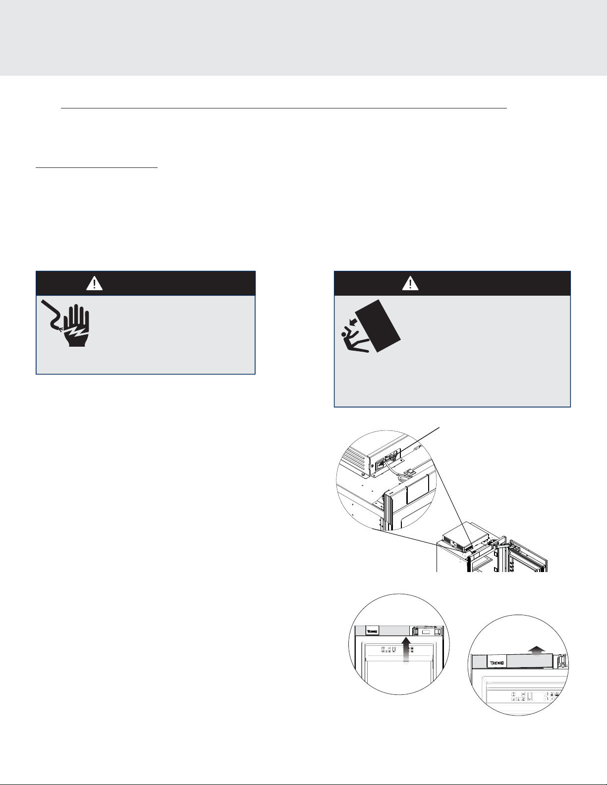
WARNING
ELECTRICAL SHOCK HAZARD
Disconnect power or turn
power disconnect switch to
OFF position before removing top grille.
Failure to do so can result in death or electrical shock.
Power On/O Switch
Your unit is shipped with the power switch on. When rst plugged in, the
display will ash. Push any button to initiate display.
The power on/o switch is located to the left of the center behind the
header panel. It is used to turn the power o when cleaning or servicing the
refrigerator.
To turn the power o , remove the header panel by using a small at head
screwdriver to pry between the breaker frame and the header panel on the
side closest to the hinge (see drawing A). There is a small pocket cut into the
bottom of the header panel at that location for that purpose. Once you have
pulled the header panel away from the unit (drawing B) enough to get your
ngers behind it slowly pull the opposite side away from the unit.
NOTE: There are wires connected to the backside of the header panel for the
Viking light and the WiFi board on the back of the light.
WARNING
TIP OVER HAZARD
Appliance is top heavy and tips easily
when not completely installed. Keep
doors closed until appliance is completely
installed and secured per installation
instructions.
Use two or more people to move and install appliance.
Failure to do so can result in death or serious injury.
power switch
A
B
To turn power on, press power on/o switch to the on position. Replace
header panel. IMPORTANT: Be sure the power on/o switch is in the on
position after cleaning or servicing.
4
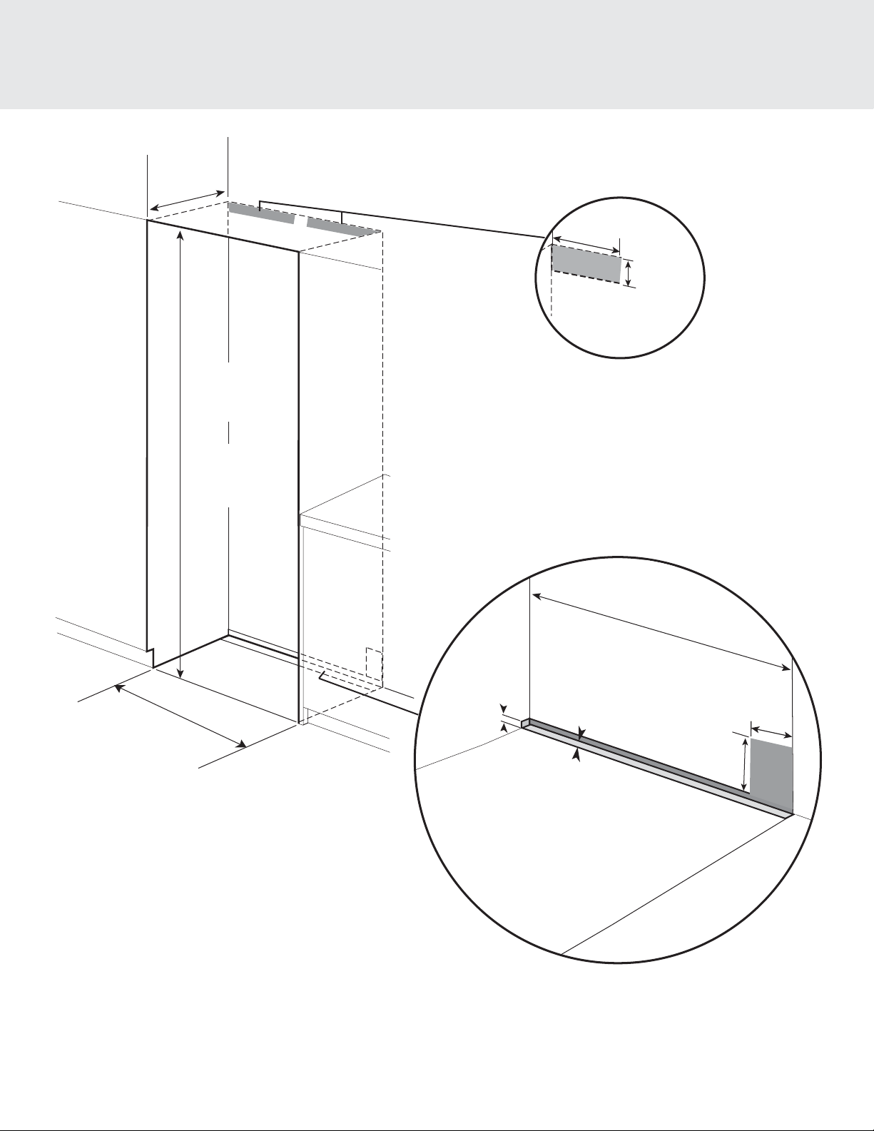
Cutout Dimensions
*
25”
(63.5 cm)
84”
(213.4 cm) min.
opening height
85-3/16”
(216.3cm) max.
opening height
Can be located on either side
Electric Outlet Location
15-1/2”
(39.4 cm)
4-1/4”
(10.8 cm)
+
leveling
dimension
Water Line Entry Area
*Refer to Specfication
chart for
specific Models
*Note: For all models, 3” back from the front of the
cabinet on both sides needs to fi nished like the outside
of the cabinets
5/8”
(1.6 cm)
1/2”
(1.3 cm)
*Cutout
Width
6”
(15.2 cm)
3”
(7.6 cm)
5
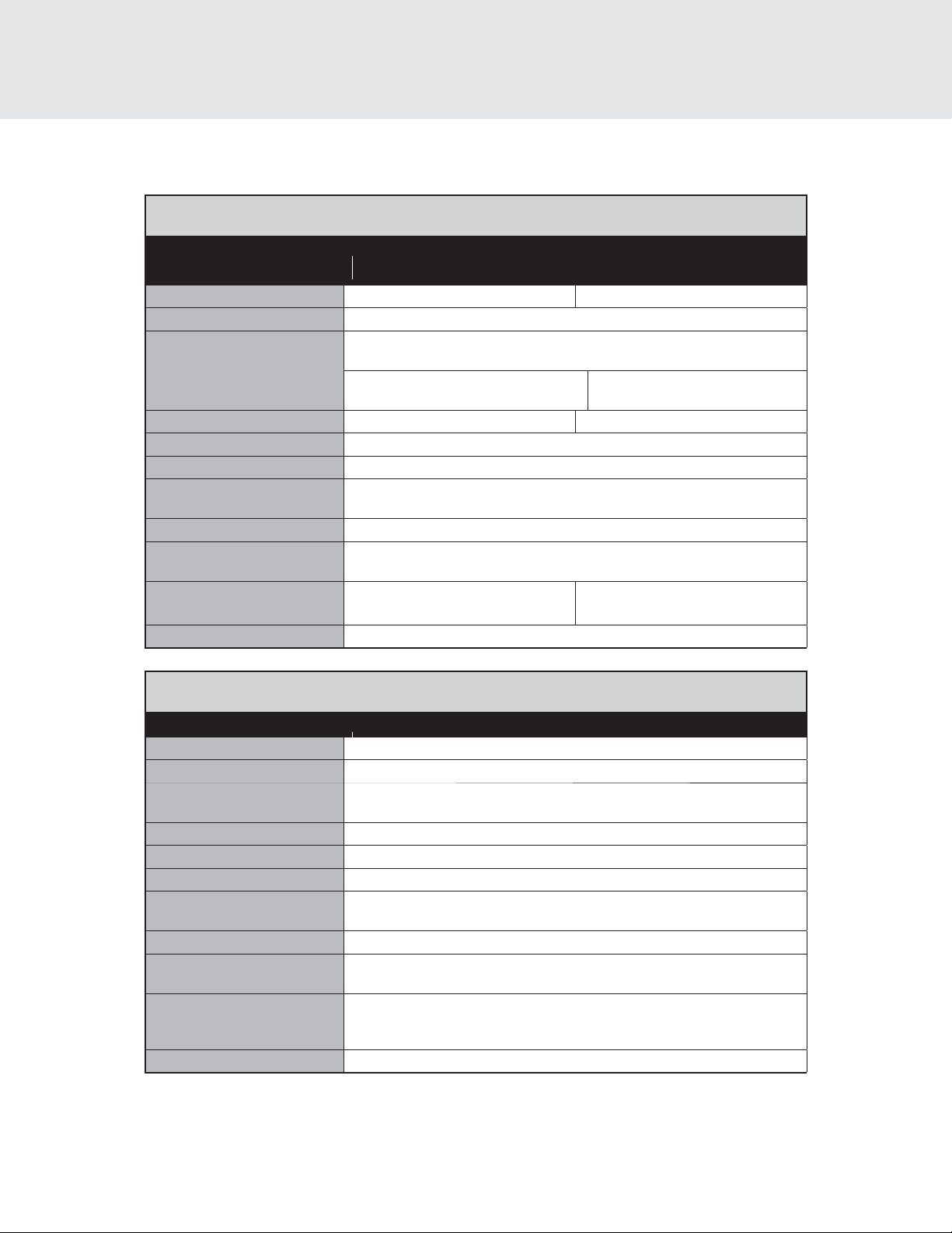
Speci cations (VRI/FRI/MVRI)
Integrated All Refrigerator
Description VRI MVRI
Overall width 24" (61.0 cm) 24" (61.0 cm)
Overall height (from bottom) 83-15/16" (213.2 cm) min to 84-3/4" (215.7 cm) max
Overall depth from rear To front edge kickplate: 22-1/16” (56.0 cm)
Cutout width 24" (61.0 cm) 24" (61.0 cm)
Cutout height 84" (213.4 cm) min to 85-3/16" (216.3 cm) max
Cutout depth 25” (63.5 cm) min.
Electrical requirements 115 volt, 60 Hz, 15 amp dedicated circuit; 3-wire cord with
Maximum amp usage 9.9 amps
Inlet water requirements 1/4” copper tubing inlet waterline; minimum 20 psi;
Overall interior capacity
Refrigerator
24" 24"
To front of door panel: 24-3/4” (62.9 cm)
To front of handle endcap:
27-11/16" (70.3 cm)
grounded 3-prong plug attached to product
maximum 120 psi
12.9 cu. ft.
(366.9 liters)
To front of handle endcap:
27-5/16" (69.4 cm)
12.9 cu. ft.
(366.9 liters)
Approximate shipping weight 450 lbs. (202.5 kg)
Integrated All Refrigerator w/Custom Panel
Description FRI - 24"
Overall width 24" (61.0 cm)
Overall height (from bottom) 83-15/16" (213.2 cm) min to 84-3/4" (215.7 cm) max
Overall depth from rear To front edge kickplate: 22-1/16” (56.0 cm)
To front of door panel: 24” (61.0 cm)
Cutout width 24" (61.0 cm)
Cutout height 84" (213.4 cm) min to 85-3/16" (216.3 cm) max
Cutout depth 25” (63.5 cm) min.
Electrical requirements 115 volt, 60 Hz, 15 amp dedicated circuit; 3-wire cord with
grounded 3-prong plug attached to product
Maximum amp usage 9.9 amps
Inlet water requirements 1/4” copper tubing inlet waterline; minimum 20 psi;
maximum 120 psi
Overall interior capacity
Refrigerator 12.9 cu. ft. (366.9 liters)
Approximate shipping weight 450 lbs. (202.5 kg)
6
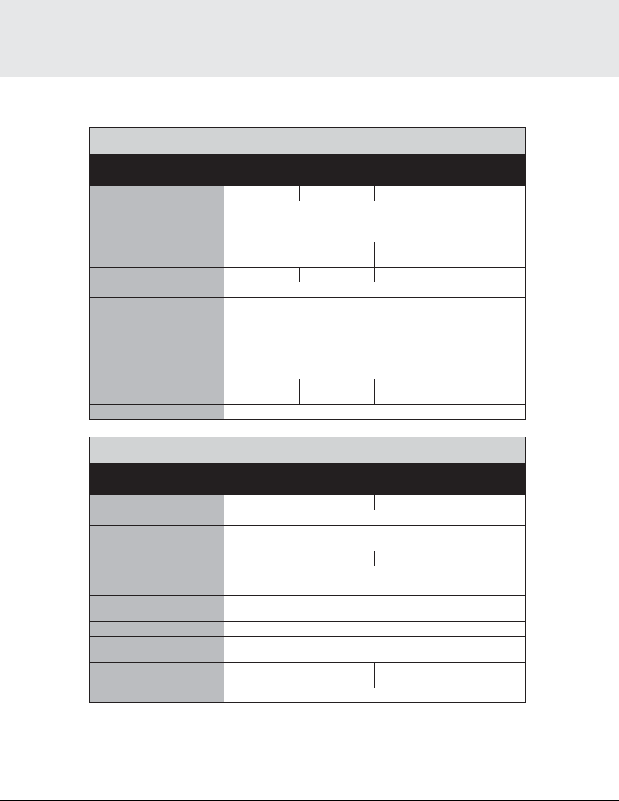
Speci cations ( VFI/FFI/MVFI)
Integrated All Freezer
Description VFI MVFI
Overall width 18" (45.7 cm) 24" (61.0 cm) 18" (45.7 cm) 24" (61.0 cm)
Overall height (from bottom) 83-15/16" (213.2 cm) min to 84-3/4" (215.7 cm) max
Overall depth from rear To front edge kickplate: 22-1/16” (56.0 cm)
Cutout width 18" (45.7 cm) 24" (61.0 cm) 18" (45.7 cm) 24" (61.0 cm)
Cutout height 84" (213.4 cm) min to 85-3/16" (216.3 cm) max
Cutout depth 25” (63.5 cm) min.
Electrical requirements 115 volt, 60 Hz, 15 amp dedicated circuit; 3-wire cord with
Maximum amp usage 9.9 amps
Inlet water requirements 1/4” copper tubing inlet waterline; minimum 20 psi;
Overall interior capacity
Freezer
Approximate shipping weight 450 lbs. (202.5 kg)
(238.9 liters)
18" 24" 18" 24"
To front of door panel: 24” (61.0 cm)
To front of handle endcap:
27-11/16" (70.3 cm)
grounded 3-prong plug attached to product
8.4 cu. ft.
12.2 cu. ft.
(361.2 liters)
maximum 120 psi
To front of handle endcap:
27-5/16" (69.4 cm)
8.4 cu. ft.
(238.9 liters)
(361.2 liters)
12.2 cu. ft.
Integrated All Freezer W/Custom Panel
Description FFI
18" 24"
Overall width 18" (45.7 cm) 24" (61.0 cm)
Overall height (from bottom) 83-15/16" (213.2 cm) min to 84-3/4" (215.7 cm) max
Overall depth from rear To front edge kickplate: 22-1/16” (56.0 cm)
To front of door panel: 24” (61.0 cm)
Cutout width 18" (45.7 cm) 24" (61.0 cm)
Cutout height 84" (213.4 cm) min to 85-3/16" (216.3 cm) max
Cutout depth 25” (63.5 cm) min.
Electrical requirements 115 volt, 60 Hz, 15 amp dedicated circuit; 3-wire cord with
grounded 3-prong plug attached to product
Maximum amp usage 9.9 amps
Inlet water requirements 1/4” copper tubing inlet waterline; minimum 20 psi;
maximum 120 psi
Overall interior dimensions
Freezer
Approximate shipping weight 565 lbs. (254.3 kg)
8.4 cu. ft.
(238.9 liters)
12.2 cu. ft.
(361.2 liters)
7
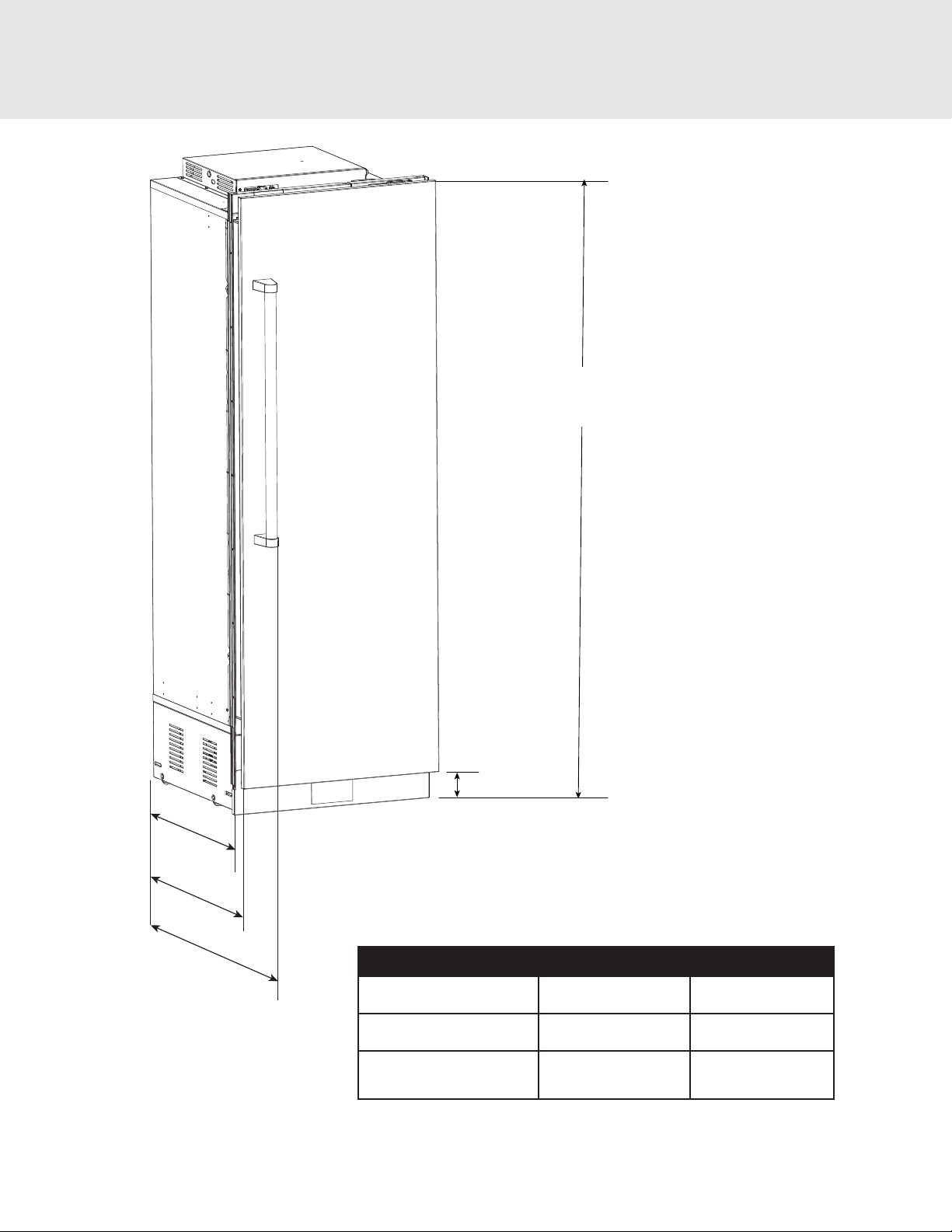
Dimensions (VRI/FRI/MVRI)
83-15/16”
(213.2 cm)
22-1/16”
(56.0 cm)
B
A
Model Dimension A Dimension B*
VRIVFI
FRI/FFI
MVRI/MVFI
4-1/16”
(10.3 cm)
27-11/16" (70.3 cm) 24-3/4" (62.9 cm)
N/A 24" (61.0 cm)
27-5/16" (69.4 cm) 24-3/4" (62.9 cm)
*To outside of door panel
8
 Loading...