

Viking MB 650, MB 655 Repair Instructions

EN
Repair instructions
2008 - 05
www.viking-garden.com
MB 650, MB 655
- Notes on the repair instructions -
Notes on the repair instructions
2. End of modified operations
3. Continuation of further, unmodified
operations
from serial number 9 xx xxx xxx
Marks the further operations which
are required for the completion of this
section.
x.x.x (A)
x.x.x (A)
1. Beginning of one or of several
modified operation(s)
The black bar with the serial number
marks the beginning of one or several
modified operations.
Marks the end of one or of several
modified operation(s).
No further operations must be
performed for the completion of this
section.
Marks the end of one or of several
modified operation(s).
Further unmodified operations are
required for the completion of this
section
(see pt. 3)
General:
For easier use and better
understanding of these repair
instructions, graphic symbols with the
following meanings are used in the
text and illustrations:
In the text:
• = operation to be performed, which
corresponds to the illustration
(above the text field).
- = operation to be performed, but
which is not shown in the
illustration (above the text field).
The item numbers contained in the
text refer exclusively to the illustration
above the relevant text field.
Modifications:
The appliances described in these
repair instructions are subject to
technical improvements and
modifications, which also affect the
individual operations.
Modified operations are documented
as follows:
The beginning and end of one
operation, or of several sequential
operations, are marked by two black
bars.
2 RA_6360_6375_01 - EN

- Contents -
01. Preface 7
02. Handlebar 8
02.01 Replacing cable guide 8
02.01.01 Removing right / left cable guide 8
02.01.02 Installing right / left cable guide 8
02.02 Replacing reinforcement strut 8
02.02.01 Removing reinforcement strut 8
02.02.02 Installing reinforcement strut 8
02.03 Opening housing halves 8
02.03.01 Removing inside right housing half 8
02.03.02 Removing outside right housing half 9
02.03.03 Removing inside left housing half 9
02.03.04 Removing outside left housing half 10
02.04 Closing housing halves 11
02.04.01 Attaching outside right housing half 11
02.04.02 Attaching inside right housing half 11
02.04.03 Attaching outside left housing half 11
02.04.04 Attaching inside left housing half 12
02.05 Replacing housing halves 12
02.05.01 Removing / dismantling inside
right housing half 12
02.05.02 Attaching / assembling inside
right housing half 12
02.05.03 Removing / dismantling inside
left housing half 13
02.05.04 Assembling inside left housing half 13
02.05.05 Dismantling outside left housing half 13
02.05.06 Assembling outside left housing half 13
02.05.07 Dismantling outside right housing half 13
02.05.08 Attaching outside right housing half 13
02.06 Replacing upper handlebar 14
02.06.01 Removing upper handlebar 14
02.06.02 Attaching upper handlebar 14
02.07 Replacing cable anti-kink protection 14
02.07.01 Removing cable anti-kink protection 14
02.07.02 Installing cable anti-kink protection 15
02.08 Replacing starter cable guide 15
02.08.01 Removing starter cable guide 15
02.08.02 Installing starter cable guide 15
02.09 Replacing centre handlebar section 16
02.09.01 Removing left centre handlebar section 16
02.09.02 Installing left centre handlebar section 16
02.09.03 Removing right centre handlebar section 17
02.09.04 Installing right centre handlebar section 17
02.10 Replacing lower handlebar 18
02.10.01 Removing left lower handlebar 18
02.10.02 Installing left lower handlebar 18
02.10.03 Removing right lower handlebar 19
02.10.04 Installing right lower handlebar 20
02.11 Replacing handlebar height adjustment 21
02.11.01 Removing handlebar height adjustment 21
02.11.02 Installing handlebar height adjustment 21
02.12 Replacing charging socket 22
02.12.01 Removing charging socket 22
02.12.02 Installing charging socket 22
02.13 Replacing ignition lock 23
02.13.01 Removing ignition lock 23
02.13.02 Installing ignition lock 23
03. Control bars and levers 24
03.01 Replacing wheel drive control bar 24
03.01.01 Removing wheel drive control bar 24
03.01.02 Installing wheel drive control bar 24
03.02 Replacing motorstop control bar 24
03.02.01 Removing motorstop control bar 24
03.02.02 Installing motorstop control bar 25
03.03 Replacing blade stop /
Quick-Start control bar 25
03.03.01 Removing blade stop /
Quick-Start control bar 25
03.03.02 Installing blade stop /
Quick-Start control bar 26
03.04 Replacing blade clutch /
Quick-Start lever 27
03.04.01 Removing blade clutch /
Quick-Start lever 27
03.04.02 Dismantling blade clutch /
Quick-Start lever 27
03.04.03 Assembling blade clutch /
Quick-Start lever 28
03.04.04 Installing blade clutch / Quick-Start lever 28
03.05 Replacing detent lever 29
03.05.01 Removing detent lever 29
03.05.02 Installing detent lever 29
03.06 Replacing locking lever 29
03.06.01 Removing locking lever 29
03.06.02 Installing locking lever 30
03.07 Replacing Vario /three-speed lever 30
03.07.01 Removing Vario /three-speed lever 30
03.07.02 Installing Vario /three-speed lever 31
03.08 Replacing bracket 32
03.08.01 Removing bracket 32
03.08.02 Installing bracket 33
03.09 Replacing throttle lever 33
03.09.01 Removing throttle lever 33
03.09.02 Installing throttle lever 34
04. Chassis 35
04.01 Replacing front axle 35
04.01.01 Removing front axle 35
04.01.02 Dismantling front axle 36
04.01.03 Assembling front axle 36
04.01.04 Installing front axle 36
04.02 Replacing rear axle 37
04.02.01 Removing rear axle (with gearbox) 37
04.02.02 Dismantling rear axle 39
04.02.03 Assembling rear axle 40
04.02.04 Installing rear axle (with gearbox) 43
04.03 Replacing wheel cap 45
04.03.01 Removing front wheel cap 45
04.03.02 Removing rear wheel cap 45
04.03.03 Installing front wheel cap 46
04.03.04 Installing rear wheel cap 46
04.04 Replacing wheel 46
04.04.01 Removing front wheel 46
04.04.02 Removing rear wheel 47
04.04.03 Installing front wheel 48
04.04.04 Installing rear wheel 48
Contents
3 RA_6360_6375_01 - EN

- Contents -
Contents
04.05 Replacing wheel bearing 49
04.05.01 Removing wheel bearing 49
04.05.02 Installing wheel bearing 50
04.06 Replacing rear wheel cover 50
04.06.01 Removing rear wheel cover 50
04.06.02 Installing rear wheel cover 51
04.07 Replacing drive pinion 51
04.07.01 Removing right drive pinion 51
04.07.02 Removing left drive pinion 51
04.07.03 Installing right drive pinion 52
04.07.04 Installing left drive pinion 52
04.08 Replacing freewheel wedge 52
04.08.01 Removing right freewheel wedge 52
04.08.02 Removing left freewheel wedge 53
04.08.03 Installing right freewheel wedge 53
04.08.04 Installing left freewheel wedge 54
04.09 Replacing drive shaft bearing 54
04.09.01 Removing drive shaft bearing 54
04.09.02 Installing drive shaft bearing 54
04.10 Replacing carrying handle 54
04.10.01 Removing carrying handle 54
04.10.02 Installing carrying handle 54
05. Housing 55
05.01 Replacing housing 55
05.01.01 Removing housing 55
05.01.02 Installing housing 55
05.02 Replacing housing cover assembly 55
05.02.01 Removing housing cover assembly 55
05.02.02 Dismantling housing cover assembly 56
05.02.03 Assembling housing cover assembly 56
05.02.04 Attaching housing cover assembly 56
05.03 Replacing height adjustment handle 57
05.03.01 Removing height adjustment handle 57
05.03.02 Installing height adjustment handle 58
05.04 Replacing spring 58
05.04.01 Removing spring 58
05.04.02 Installing spring 58
05.05 Replacing flap 59
05.05.01 Removing flap 59
05.05.02 Dismantling flap 59
05.05.03 Assembling flap 59
05.05.04 Installing flap 59
05.06 Replacing handle shell 60
05.06.01 Removing handle shell 60
05.06.02 Installing handle shell 60
05.07 Replacing translatory lever cover 60
05.07.01 Removing translatory lever cover 60
05.07.02 Dismantling translatory lever cover 61
05.07.03 Assembling translatory lever cover 61
05.07.04 Installing translatory lever cover 61
05.08 Replacing sight glass 61
05.08.01 Removing sight glass 61
05.08.02 Installing sight glass 62
05.09 Replacing V-belt cover 62
05.09.01 Removing V-belt cover 62
05.09.02 Installing V-belt cover 62
05.10 Replacing left/right protection bumpers 63
05.10.01 Removing left/right protection bumpers 63
05.10.02 Installing left/right protection bumpers 63
05.11 Replacing guiding plate 63
05.11.01 Removing guiding plate 63
05.11.02 Installing guiding plate 64
05.12 Replacing lower cover 64
05.12.01 Removing lower cover 64
05.12.02 Attaching lower cover 64
06. Gearbox 65
06.01 Replacing gearbox 65
06.01.01 Removing gearbox 65
06.01.02 Installing gearbox 65
06.02 Replacing V-belt pulley 65
06.02.01 Removing single-speed V-belt pulley 65
06.02.02 Installing single-speed V-belt pulley 66
06.02.03 Removing Vario V-belt pulley and adjusting
element 66
06.02.04 Installing Vario V-belt pulley and adjusting
element 67
06.02.05 Removing three-speed V-belt pulley 68
06.02.06 Installing three-speed V-belt pulley 68
06.03 Replacing Vario V-belt pulley ball bearing 69
06.03.01 Removing Vario V-belt pulley ball bearing 69
06.03.02 Installing Vario V-belt pulley ball bearing 69
06.04 Replacing gearbox support 70
06.04.01 Removing single-speed / Vario gearbox
support 70
06.04.02 Installing single-speed / Vario gearbox
support 70
06.04.03 Removing three-speed gearbox support 70
06.04.04 Installing three-speed gearbox support 70
06.05 Replacing wheel drive lever return spring 71
06.05.01 Removing Vario gearbox return spring 71
06.05.02 Installing Vario gearbox return spring 71
06.05.03 Removing three-speed gearbox
return spring 71
06.05.04 Installing three-speed gearbox
return spring 71
06.06 Replacing cable support 72
06.06.01 Removing cable support 72
06.06.02 Installing cable support 72
07. Height adjustment 73
07.01 Replacing height adjustment spring 73
07.01.01 Removing height adjustment spring 73
07.01.02 Installing height adjustment spring 73
07.02 Replacing detent segment tension spring 74
07.02.01 Removing detent segment tension spring 74
07.02.02 Installing detent segment tension spring 74
4 RA_6360_6375_01 - EN

- Contents -
5
Contents
07.03 Replacing translatory lever 74
07.03.01 Removing translatory lever 74
07.03.02 Installing translatory lever 75
07.04 Replacing detent segment 77
07.04.01 Removing detent segment 77
07.04.02 Dismantling detent segment 77
07.04.03 Assembling detent segment 77
07.04.04 Installing detent segment 78
07.05 Replacing height adjustment indicator 78
07.05.01 Removing height adjustment indicator 78
07.05.02 Installing height adjustment indicator 78
08. Console 79
08.01 Replacing strut 79
08.01.01 Removing strut 79
08.01.02 Installing strut 79
08.02 Replacing left / right cover 79
08.02.01 Removing left / right cover 79
08.02.02 Installing left / right cover 80
08.03 Replacing console 80
08.03.01 Removing left console 80
08.03.02 Installing left console 80
08.03.03 Removing right console 81
08.03.04 Installing right console 81
09. Mowing blade 82
09.01 Replacing mowing blade 82
09.01.01 Removing mowing blade 82
09.01.02 Installing mowing blade 83
10. Blade bushing 84
10.01 Replacing blade bushing 84
10.01.01 Removing blade bushing 84
10.01.02 Installing blade bushing 84
11. Blade clutch 86
11.01 Replacing blade mounting 86
11.01.01 Removing blade mounting 86
11.01.02 Dismantling blade mounting 86
11.01.03 Assembling blade mounting 86
11.01.04 Installing blade mounting 86
11.02 Replacing clutch linings 87
11.02.01 Removing clutch linings 87
11.02.02 Installing clutch linings 87
11.03 Replacing stop plate 87
11.03.01 Removing stop plate 87
11.03.02 Installing stop plate 88
11.04 Replacing thrust springs 88
11.04.01 Removing thrust springs 88
11.04.02 Installing thrust springs 88
11.05 Replacing clutch shoes 89
11.05.01 Removing clutch shoes 89
11.05.02 Installing clutch shoes 89
11.06 Replacing blade mounting ball bearing 89
11.06.01 Removing blade mounting ball bearing 89
11.06.02 Installing blade mounting ball bearing 90
11.07 Replacing clutch drum 90
11.07.01 Removing clutch drum 90
11.07.02 Installing clutch drum 91
11.08 Replacing brake band lever 92
11.08.01 Removing brake band lever 92
11.08.02 Installing brake band lever 93
11.09 Replacing brake band 94
11.09.01 Removing brake band 94
11.09.02 Installing brake band 94
11.10 Replacing clutch flange 94
11.10.01 Removing clutch flange 94
11.10.02 Dismantling clutch flange 95
11.10.03 Assembling clutch flange 95
11.10.04 Installing clutch flange 96
12. Engine 98
12.01 Deactivating Quick-Start 98
12.02 Replacing engine cover 98
12.02.01 Removing engine cover 98
12.02.02 Attaching engine cover 99
12.03 Replacing V-belt pulley 99
12.03.01 Removing V-belt pulley 99
12.03.02 Installing V-belt pulley 99
12.04 Replacing V-belt 100
12.04.01 Removing V-belt 100
12.04.02 Installing V-belt 101
12.05 Replacing engine 102
12.05.01 Removing engine 102
12.05.02 Installing engine 104
12.06 Replacing vibration damper 107
12.06.01 Removing vibration damper 107
12.06.02 Installing vibration damper 107
13. Starter battery 108
13.01 Removing starter battery 108
13.01.01 Disconnecting starter battery 108
13.01.02 Removing starter battery 108
13.02 Installing starter battery 108
13.02.01 Mounting starter battery 108
13.02.02 Connecting starter battery 109
14. Cables, wiring harness 110
14.01 Replacing motorstop cable 110
14.01.01 Detaching motorstop cable 110
14.01.02 Attaching motorstop cable 110
14.02 Replacing blade clutch /
Quick-Start cable 110
14.02.01 Detaching blade clutch /
Quick-Start cable 110
14.02.02 Attaching blade clutch /
Quick-Start cable 110
14.03 Replacing wheel drive cable 110
14.03.01 Detaching wheel drive cable 110
14.03.02 Attaching wheel drive cable 110
14.03.03 Adjusting wheel drive cable 111
RA_6360_6375_01 - EN

RA_6360_6375_01 - EN 6
14.04 Replacing Vario / three-speed drive speed
control cable 111
14.04.01 Detaching Vario / three-speed drive speed
control cable 111
14.04.02 Attaching Vario / three-speed drive speed
control cable 111
14.05 Replacing throttle cable 111
14.05.01 Detaching throttle cable 111
14.05.02 Attaching throttle cable 111
14.06 Replacing wiring harness 112
14.06.01 Disconnecting wiring harness 112
14.06.02 Connecting wiring harness 112
14.07 Cable, wiring harness guide 112
14.07.01 MB 650.0 T 113
14.07.02 MB 650.0 V/VM, MB 655.0 V/VM 113
14.07.03 MB 650.0 VS 114
14.07.04 MB 650.0 VE 114
14.07.05 MB 655.0 G/GM 115
14.07.06 MB 655.0 GS 115
14.07.07 MB 650.0 VQ 116
14.07.08 MB 655.0 GQ 116
14.07.09 MB 650.0 TK 117
14.07.10 MB 650.0 KS 117
14.07.11 MB 655.0 KS 118
14.07.12 MB 655.0 GK 118
14.07.13 MB 650.0 OS, MB 655.0 OS,
MB 655.1 VS 119
14.07.14 MB 655.1 V/ VM 119
14.07.15 MB 655.1 G 120
14.07.16 MB 655.1 GS 120
15. General 121
15.01 Troubleshooting 121
15.02 Maintenance table 123
15.03 Torque values 124
- Contents -
Contents

RA_6360_6375_01 - EN7
- Preface -
These repair instructions contain a
comprehensive description of all the
typical repair operations for this lawn
mower series.
The design of the
MB 650.0 T/ TK/ V/ VM/ VQ/ VS/ KS,
MB 655.0 V/ VM/ G/ GK/ GM/ GQ/
GS/ KS, MB 655.1 V/ VM/ G/ GS/ VS
lawn mowers is largely identical,
however, they represent different
equipment versions. For the
illustrations, a model version with
Vario drive and blade clutch has been
selected. The descriptions of the
repair operations generally relate to all
the mowers.
Model-specific parts and repair
operations are identified as such and
are treated separately.
Please also use the illustrated spare
parts lists when performing repair
work. These show the installation
position and assembly sequence of
the various assemblies.
To determine the part numbers of the
spare parts required, please use the
latest edition of the relevant spare
parts list (DVD-ROM).
A fault to the appliance may have
several causes. The faults known to us
with regard to this lawn mower series
are outlined in the section
“Troubleshooting” in these repair
instructions.
Refer to the “Technical Information”
(DVD-ROM), this provides information
on technical modifications which have
been implemented since these repair
instructions were written. The
Technical Information is valid until the
new edition as a supplement to the
spare parts list.
The Repair Instructions and Technical
Information should be available at the
place where the repair work is being
carried out. Distribution to third parties
is prohibited.
Only use high-quality tools,
accessories and spare parts.
Otherwise, there may be a risk of
accidents resulting in personal injury
or damage to the appliance.
VIKING recommends the use of
original VIKING tools, accessories
and spare parts. Their properties are
optimally adapted to the appliance
and the user’s requirements.
When replacing the cutting tool,
ensure that the correct type of cutting
tool is installed.
Safety instructions:
Always detach the spark plug socket
before performing any work on the
appliance;
also remove the ignition key from the
appliance (for MB 650.0 VE);
additionally deactivate the QuickStart, turn the safety key to the locked
position and remove
(for MB 650.0 VQ, MB 655.0 GQ).
Following all repair or maintenance
operations on the machine and prior
to return of the customer appliance by
the specialist dealer, it is imperative
that safety checks be performed.
If the lawn mower is operated during
repair or maintenance, the relevant
national legislation and the safety
instructions in the instruction manual
must be observed.
Petrol is highly inflammable and is
explosive under certain conditions.
Improper handling may result in burns
or other severe injuries.
Warning! Always keep heat sources
sparks and naked flames away.
All work with fuel must only be
performed out-of-doors.
Wipe up spilt fuel immediately.
Always wash hands thoroughly
following contact with used oil.
Do not allow used oil to enter into the
sewage system or penetrate into the
ground.
Collect used oil and dispose of it in an
environmentally friendly manner.
01. Preface

RA_6360_6375_01 - EN 8
- Handlebar -
02.01 Replacing cable guide
02.01.01 Removing right / left cable guide
02.01.02 Installing right / left cable guide
02.02.02 Installing reinforcement strut
02.02 Replacing reinforcement strut
02.03 Opening housing halves
02.02.01 Removing reinforcement strut
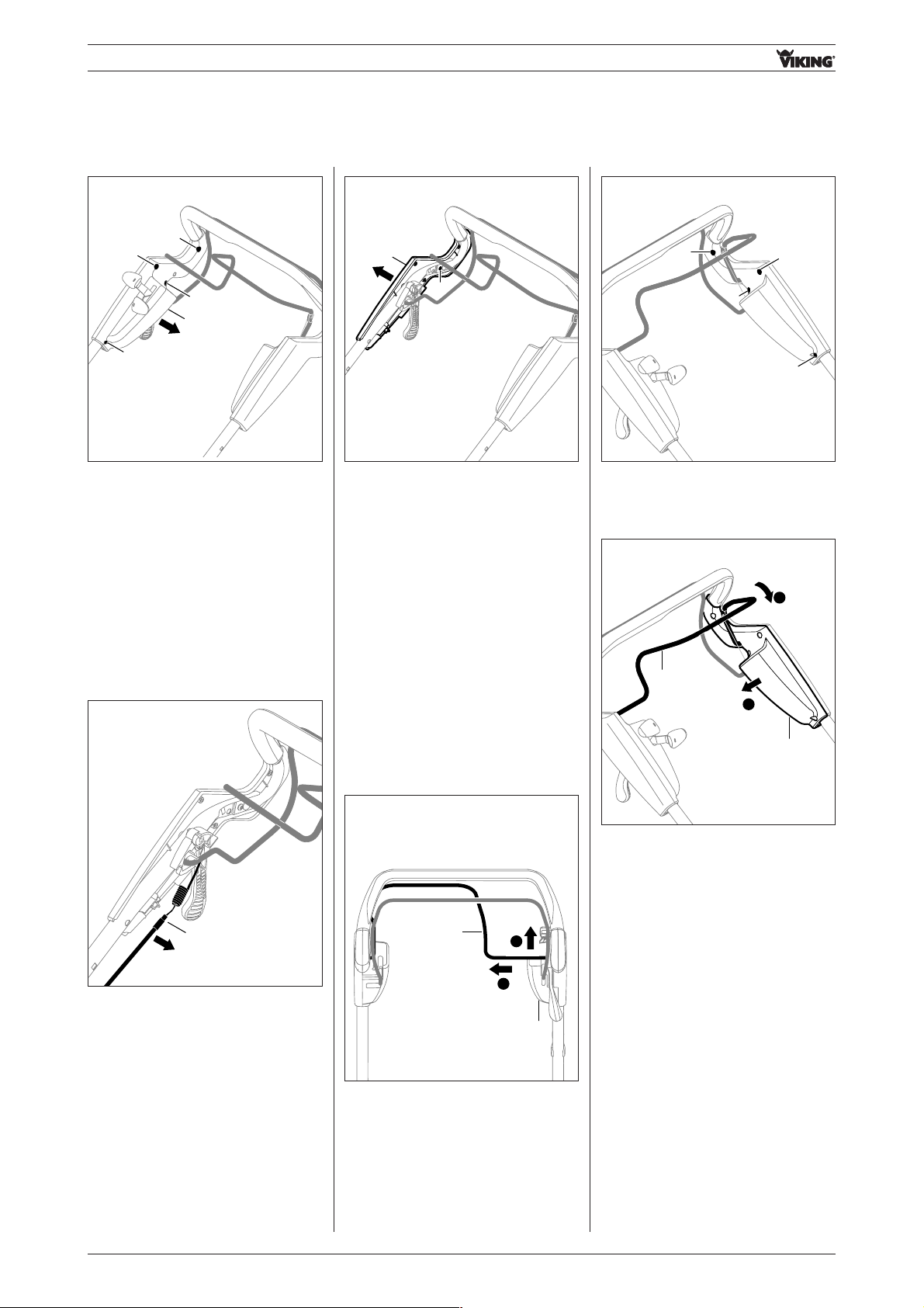
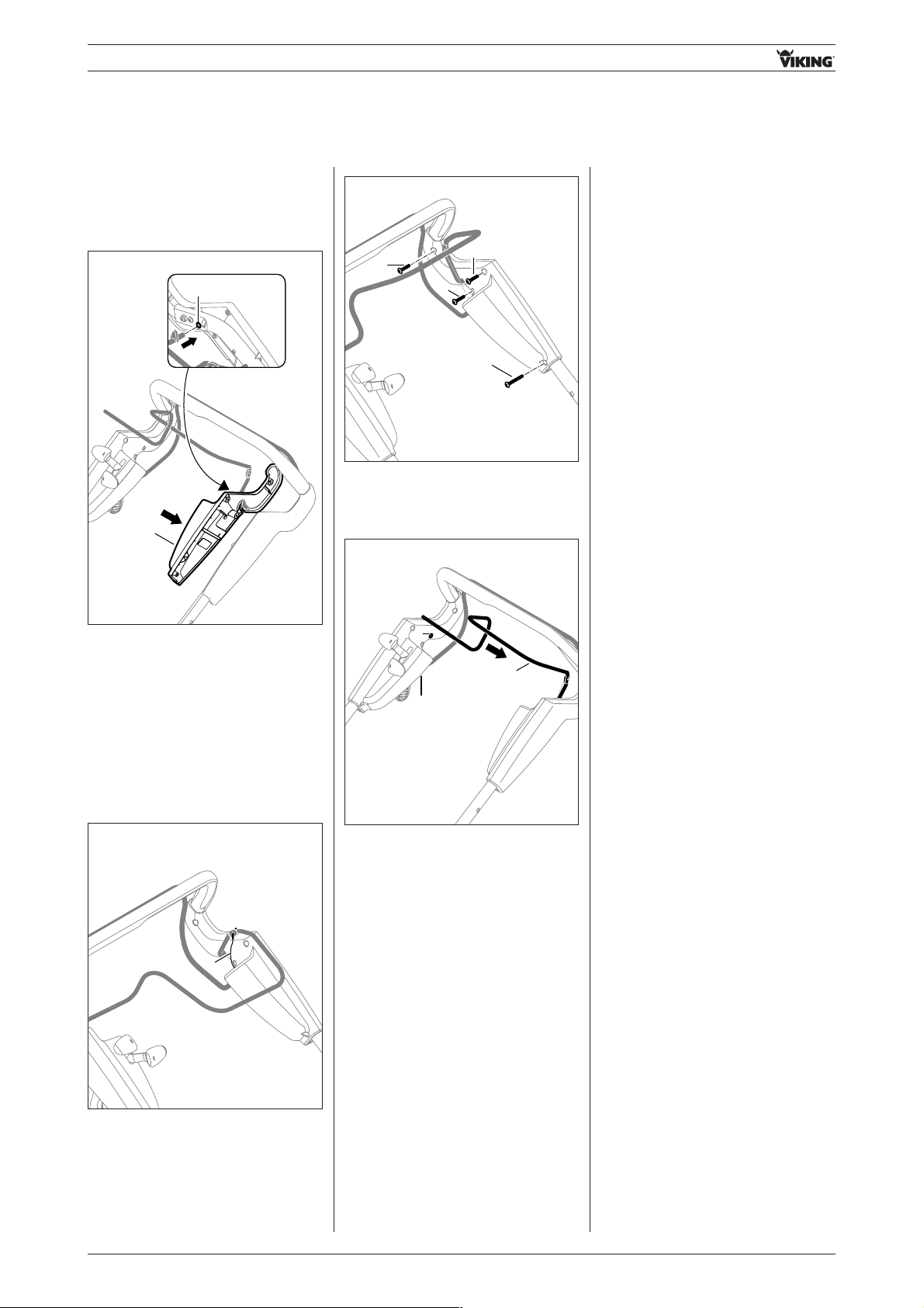
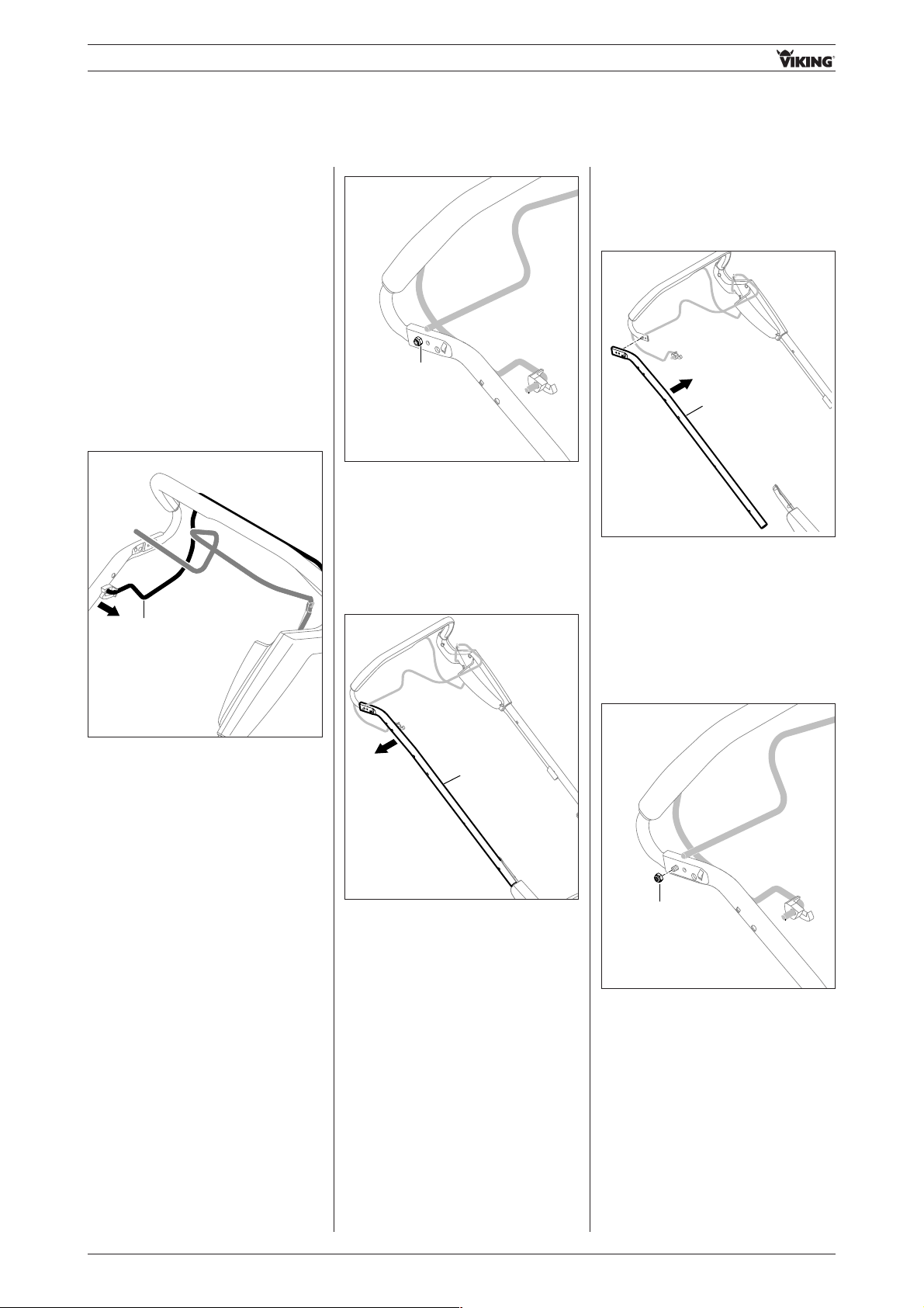
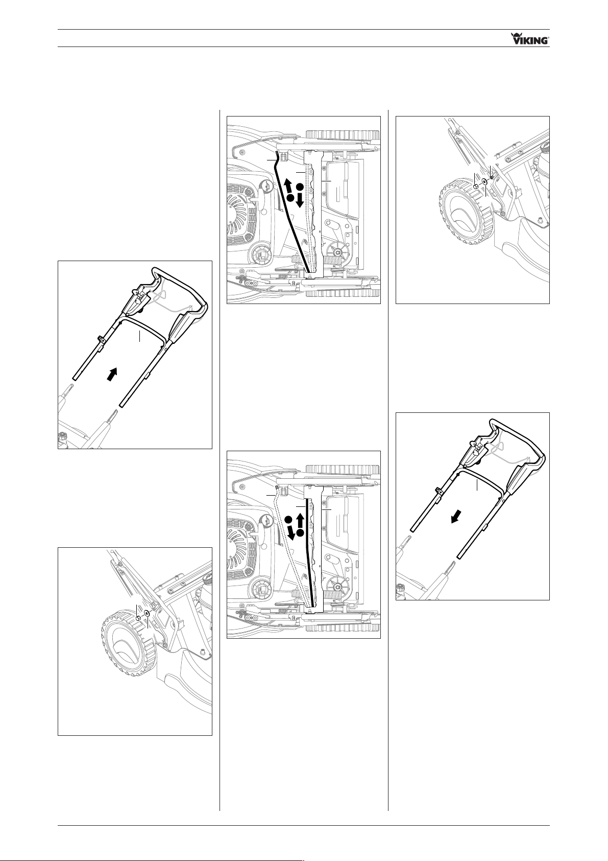
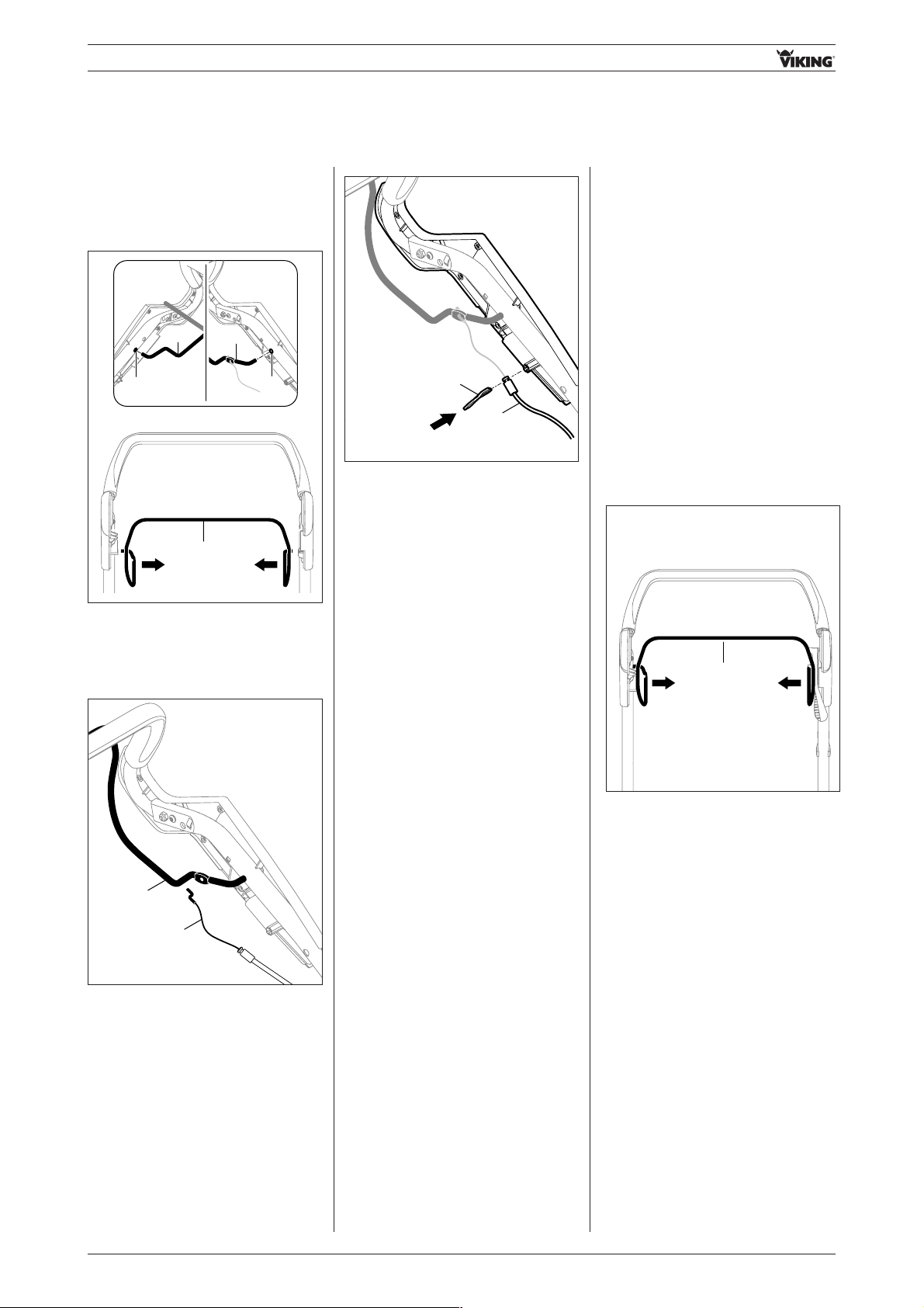
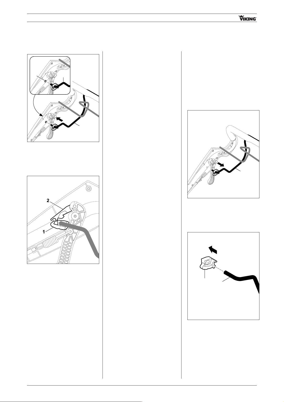
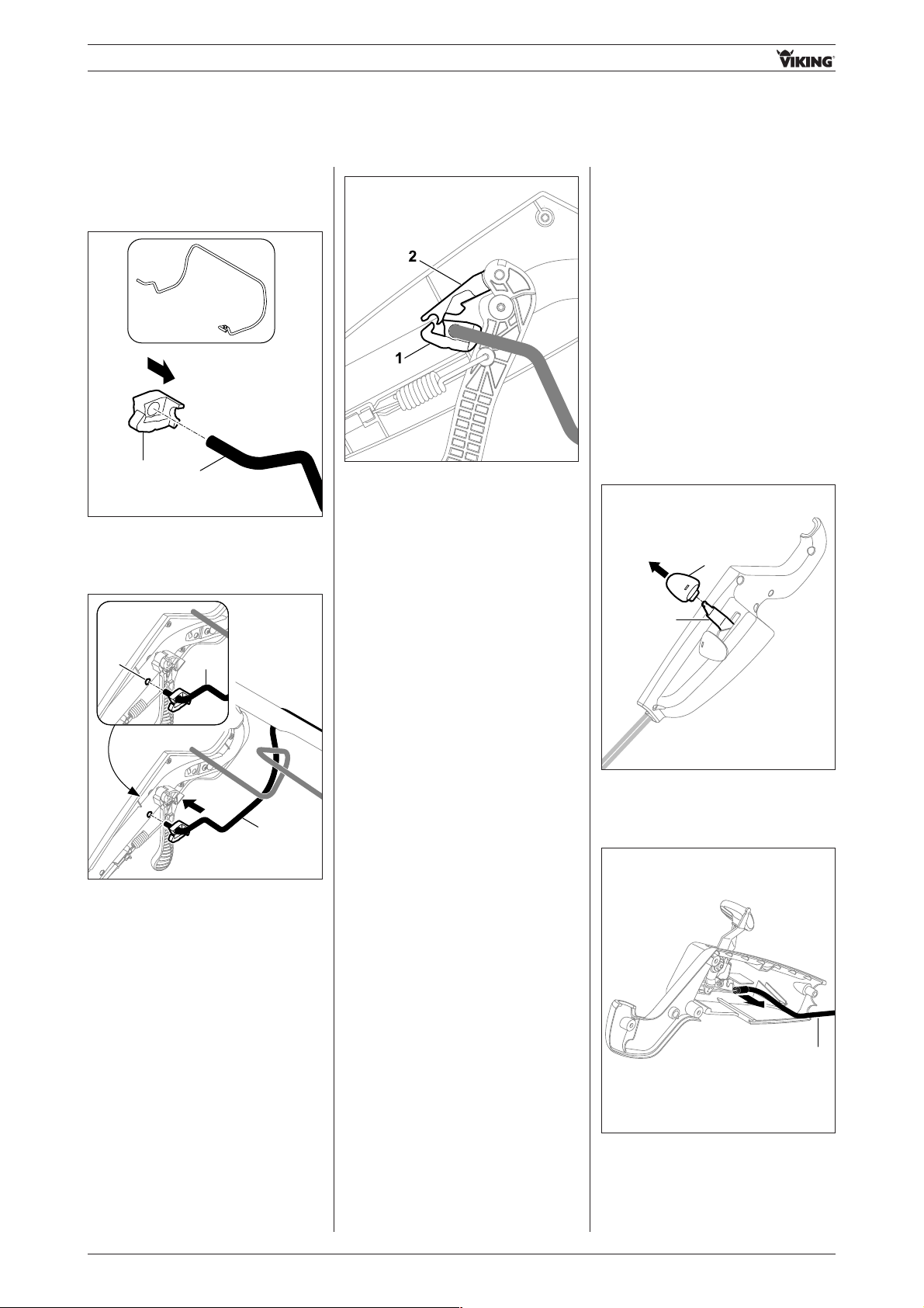
• Lever off cable guide(s) 1 from
handlebar using a screwdriver 2.
• Push cable guide(s) 1 into housing 2
and clip onto handlebar.
02. Handlebar
1
2
2
1
2
1
• Remove cap nuts 1 and remove
washers 2.
• Pull out bolts 3 from handlebar and
remove strut 4.
1
2
3
4
3
2
1
•Fit strut 1 and insert bolts 2 through
handlebar.
• Install cap nuts 4 with washers 3
and tighten (8-10 Nm).
4
3
2
1
2
3
4
02.03.01 Removing inside right housing half
- Remove right / left cable guide
(see section 02.01.01)
• Push wheel drive control bar 1 to the
left and detach from inside right
housing half 2.
• Pull wheel drive control bar 1
upwards and rest on right housing
halves.
1
2
2
1
RA_6360_6375_01 - EN9
- Handlebar -
02.03.02 Removing outside right housing half
- Remove inside right housing half
(see section 02.03.01).
Models with blade clutch / with
Quick-Start
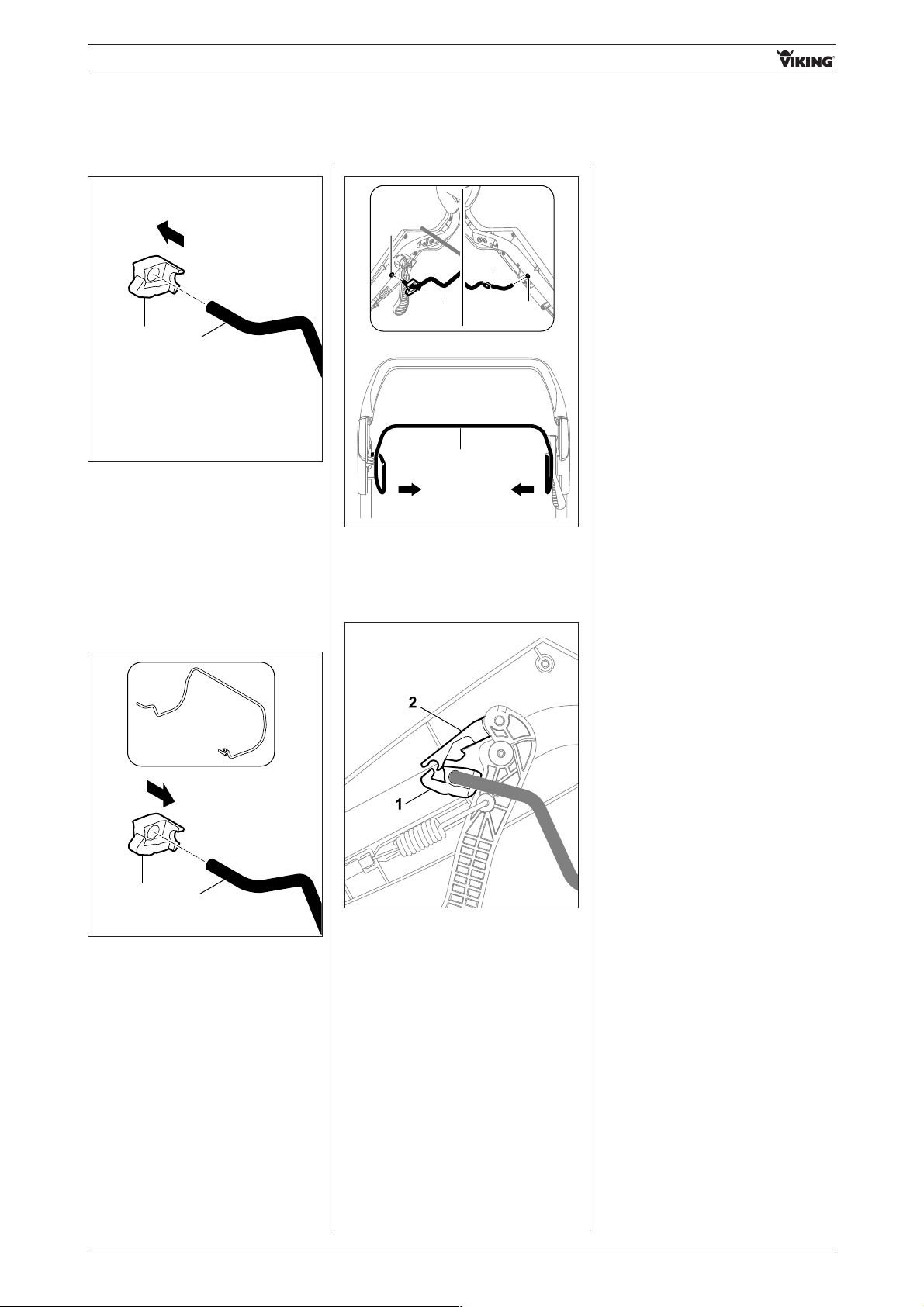
• Detach blade clutch cable 1 from
guide.
• Remove screw 1.
• Remove outside right housing
half 2.
1
2
02.03.03 Removing inside left
housing half
- Remove right / left cable guide
(see section 02.01.01)
- Remove reinforcement strut
(see section 02.02.01)
• Push wheel drive control bar 1 to the
left and detach from inside right
housing half 2.
• Pull wheel drive control bar 1
upwards and rest on right housing
halves.
1
2
2
• Remove screws 1, 2.
1
2
1
1
• Lift inside left housing half 1 slightly
and push wheel drive lever 2
forwards.
1
2
2
1
• Remove screws 1, 2 and remove
inside right housing half 3.
1
3
1
1
2
1
1
RA_6360_6375_01 - EN 10
- Handlebar -
• Detach wheel drive cable 1.
1
• Remove inside left housing half 1
together with wheel drive control
bar 2.
1
2
• Remove screw 1.
1
Models without blade clutch /
without Quick-Start
• Remove cable support 1.
1
• Remove outside left housing half 1.
1
02.03.04 Removing outside left housing half
- Remove inside left housing half
(see section 02.03.03)
RA_6360_6375_01 - EN11
- Handlebar -
02.04 Closing housing halves
02.04.02 Attaching inside right housing half
- Install reinforcement strut
(see section 02.02.02)
- Install right/left cable guide
(see section 02.01.02)
- Attach inside left housing half
(see section 02.04.02)
• Fit inside right housing half 1 onto
handlebar.
• Tighten screws 2, 3 (1-2 Nm).
1
3
2
2
2
02.04.01 Attaching outside right housing half
• Fit housing half 1 and tighten
screw 2 (1-2 Nm).
1
2
02.04.03 Attaching outside left housing half
• Fit outside left housing half 1
onto handlebar and tighten
screw 2 (1-2 Nm).
1
2
Models without blade clutch /
without Quick-Start
• Insert cable support and attach
motorstop cable.
2
1
Models with blade clutch /
with Quick-Start
• Attach blade clutch cable 1.
• Push wheel drive control bar 1 to the
left and then attach in bore A.
A
1
- Attach inside left housing half
(see section 02.04.03)
1
RA_6360_6375_01 - EN 12
- Handlebar -
02.05 Replacing housing
halves
02.05.01 Removing /
dismantling inside
right housing half
02.04.04 Attaching inside left housing half
• Attach control bar together with left
housing half 1 in bore A on
handlebar.
Note:
Ensure that control lever is
positioned on both housing halves
on the right side.
1
A
• Attach wheel drive cable 1 in wheel
drive control bar.
1
• Tighten screws 1, 2 (1-2 Nm).
2
1
1
1
• Press wheel drive control bar 1
together to the left and insert in
bore A on the right.
22
A
1
- Install right/left cable guide
(see section 02.01.02)
Models without blade clutch /
without Quick-Start
- Remove bracket
(see section 03.08.01)
Models with blade clutch
- Remove throttle lever
(see section 03.09.01)
MB 650.0 TK, MB 655.0 GK
- Remove throttle lever
(see section 03.09.01)
MB 650.0 T
- Remove inside right housing half
(see section 02.03.01)
MB 650.0 T
- Attach inside right housing half
(see section 02.04.02)
02.05.02 Attaching / assembling
inside right housing
half
Models without blade clutch /
without Quick-Start
- Install bracket
(see section 03.08.02)
Models with blade clutch
- Install throttle lever
(see section 03.09.02)
MB 650.0 TK, MB 655.0 GK
- Install throttle lever
(see section 03.09.02)
RA_6360_6375_01 - EN13
- Handlebar -
02.05.03 Removing /
dismantling inside left
housing half
MB 650.0 VE
- Remove charging socket
(see section 02.12.01)
MB 650.0 VE
- Remove ignition lock
(see section 02.13.01)
- Remove inside left housing half
(see section 02.03.03)
02.05.05 Dismantling outside left housing half
• Remove screw 1.
• Remove wheel drive cable adjusting
element 2 from outside left housing
half.
- Remove outside left housing half
(see section 02.03.04)
- Attach outside left housing half
(see section 02.04.04)
02.05.06 Assembling outside left housing half
• Insert wheel drive cable adjusting
element 1.
• Tighten screw 2 (1-2 Nm).
02.05.04 Assembling inside left housing half
- Attach inside left housing half
(see section 02.04.03)
MB 650.0 VE
- Install ignition lock
(see section 02.13.02)
MB 650.0 VE
- Install charging socket
(see section 02.12.02)
1
2
2
1
02.05.07 Dismantling outside right housing half
- Remove outside right housing half
(see section 02.03.02)
02.05.08 Attaching outside right housing half
- Attach outside right housing half
(see section 02.04.01)

RA_6360_6375_01 - EN 14
- Handlebar -
1
2
3
3
2
02.06 Replacing upper handlebar
02.06.01 Removing upper handlebar
- Remove outside left housing half
(see section 02.03.04)
• Remove nuts 1 and pull out bolts 2.
• Remove handlebar 3.
- Remove outside right housing half
(see section 02.03.02)
2
1
1
2
3
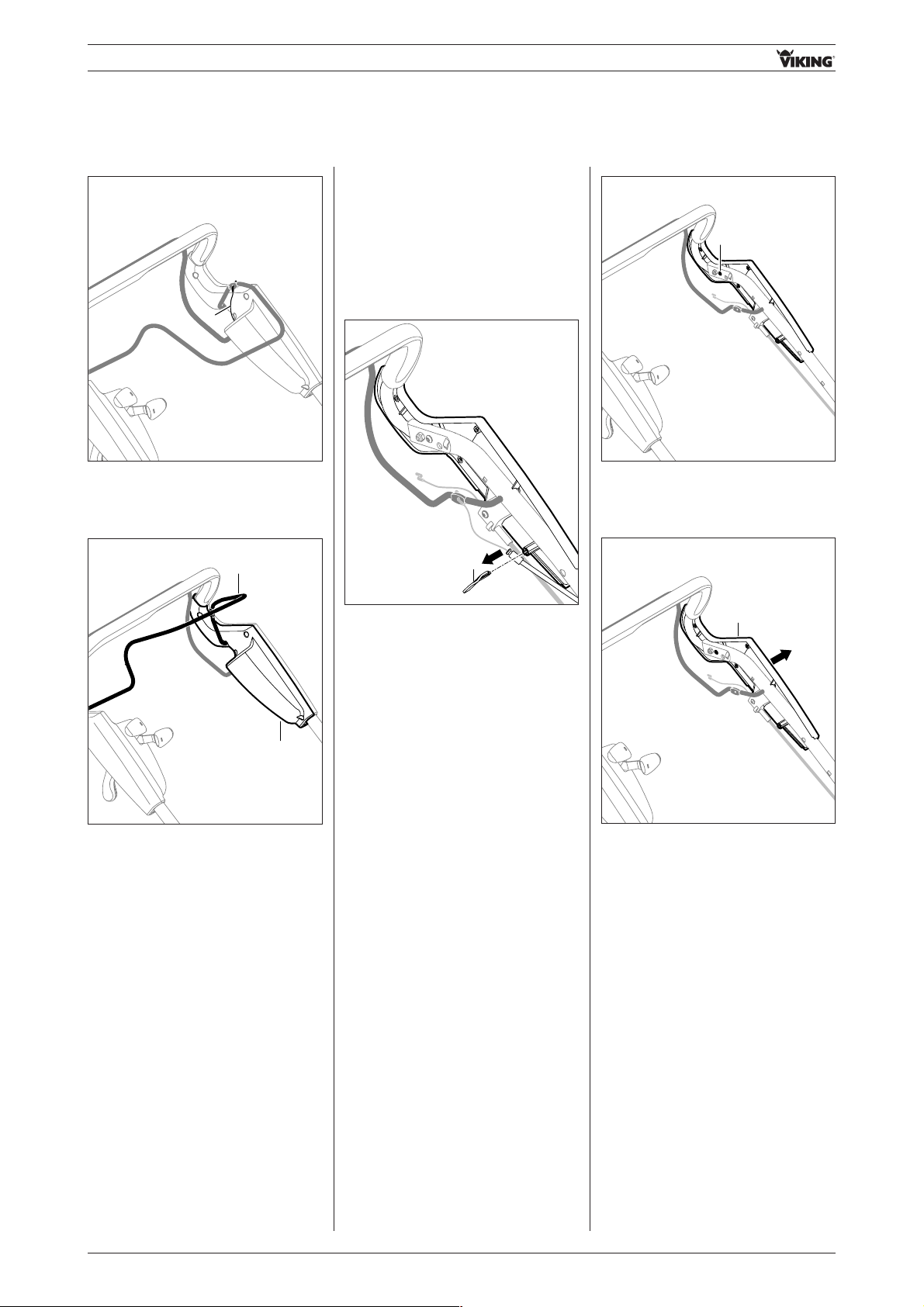
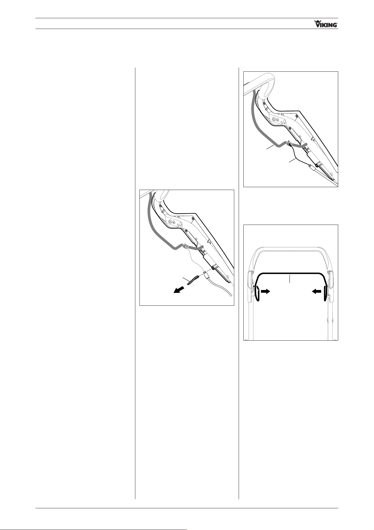
02.07 Replacing cable anti-kink protection
02.07.01 Removing cable anti-kink protection
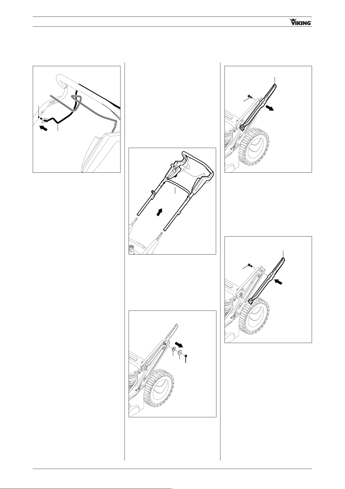
• Detach cables 1.
1
• Remove rotary handles 1.
• Remove cable anti kink protection 2/
bolt 3 from centre handlebar
section.
Note:
Only one cable anti-kink protection
2 is required on the MB 650.0 T.
A bolt 3 is installed in place of the
second cable guide.
1
1
2
2
3
02.06.02 Attaching upper handlebar
- Attach outside right housing half
(see section 02.04.01)
• Attach handlebar 1.
• Insert bolts 2 through handlebar
tube and tighten nuts 3 (8-10 Nm).
- Attach outside left housing half
(see section 02.04.04)
RA_6360_6375_01 - EN15
- Handlebar -
02.07.02 Installing cable anti-kink protection
2
2
1
1
3
1
1
1
1
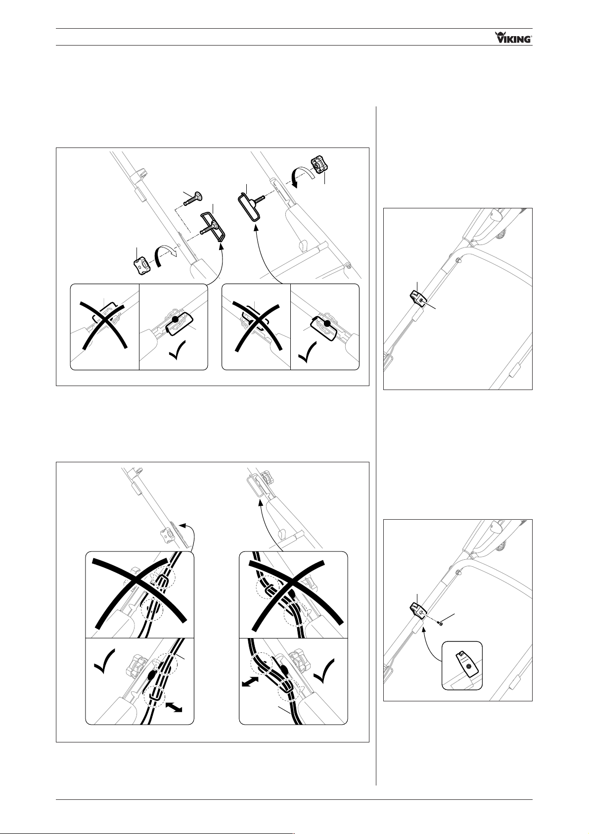
O.K.
O.K.
1
1
O.K.
O.K.
• Insert cable anti-kink protection 1/ bolt 3 in centre handlebar section
(ensure correct installation position of cable anti kink protection, see Fig.).
• Tighten rotary handles 2.
• Attach cables 1
(ensure correct installation position of cables, see Fig.).
02.08 Replacing starter cable guide
02.08.01 Removing starter cable guide
- Detach starter cable.
• Remove screw 1.
• Remove starter cable guide 2.
1
2
02.08.02 Installing starter cable guide
• Attach starter cable guide 1 to
handlebar.
• Tighten screw 2 (5-7 Nm).
- Insert starter cable.
2
1
RA_6360_6375_01 - EN 16
- Handlebar -
02.09 Replacing centre handlebar section
02.09.01 Removing left centre handlebar section
02.09.02 Installing left centre handlebar section
• Detach motorstop control bar 1 /
blade stop control bar 1 on left of
centre handlebar section.
1
• Remove left centre handlebar
section 1.
1
• Tighten nut 1 (8-10 Nm).
1
• Attach motorstop control bar 1 /
blade stop control bar 1 on left in
bore A on centre handlebar section.
1
A
1
1
• Remove nut 1.
• Attach left centre handlebar
section 1.
- Remove outside left housing half
(see section 02.03.04)
- Remove cable anti-kink protection
(see section 02.07.01)
- Install cable anti-kink protection
(see section 02.07.02)
- Attach outside left housing half
(see section 02.04.04)
RA_6360_6375_01 - EN17
- Handlebar -
02.09.03 Removing right centre handlebar section
• Detach motorstop control bar 1 /
blade stop control bar 1 on right of
centre handlebar section.
Models with blade clutch / with
Quick-Start
- Remove blade clutch / Quick-Start
lever
(see section 03.04.01)
1
• Remove nut 1.
1
• Remove right centre handlebar
section 1.
1
- Remove outside right housing half
(see section 02.03.02)
- Remove starter cable guide
(see section 02.08.01)
- Remove cable anti-kink protection
(see section 02.07.01)
- Install cable anti-kink protection
(see section 02.07.02)
02.09.04 Installing right centre
handlebar section
• Attach right centre handlebar
section 1.
1
1
• Tighten nut 1 (8-10 Nm).
RA_6360_6375_01 - EN 18
- Handlebar -
• Attach motorstop control bar 1 /
blade stop control bar 1 on right in
bore (A) on centre handlebar
section.
Models with blade clutch /
with Quick-Start
- Install blade clutch lever /
without Quick-Start
(see section 03.04.04)
1
A
- Install starter cable guide
(see section 02.08.02)
- Attach outside right housing half
(see section 02.04.01)
02.10 Replacing lower handlebar
02.10.01 Removing left lower handlebar
• Remove handlebar 1.
1
1
2
3
• Remove nut 1.
• Remove collared washer 2 and
spring washer 3.
2
1
• Pull out bolt 1 and remove left lower
handlebar 2.
- Remove cable anti-kink protection
(see section 02.07.01)
- Remove housing cover assembly
(see section 05.02.01)
02.10.02 Installing left lower handlebar
• Insert lower handlebar 1 in guide
and insert bolt 2.
1
2
RA_6360_6375_01 - EN19
- Handlebar -
- Attach housing cover assembly
(see section 05.02.04)
• Attach handlebar 1.
1
- Install cable anti-kink protection
(see section 02.07.02)
02.10.03 Removing right lower
handlebar
• Remove handlebar 1.
1
- Remove cable anti-kink protection
(see section 02.07.01)
- Remove housing cover assembly
(see section 05.02.01)
2
1
• Remove cap nut 1 and remove
washer 2.
1
2
3
• Remove nut 1.
• Remove collared washer 2 and
spring washer 3.
• Fit spring washer and collared
washer onto bolt.
Note:
Ensure correct installation position
of spring washer 1 (see Fig.).
1
2
1
2
• Tighten nut 1 (12-18 Nm).
1
RA_6360_6375_01 - EN 20
- Handlebar -
• Tighten nut 1 (12-18 Nm).
1
• Fit washer 1 onto rod 2 and tighten
cap nut 3 (12-18 Nm).
3
1
2
• Attach handlebar 1.
1
- Install cable anti-kink protection
(see section 02.07.02)
2
1
• Pull out bolt 1 and remove right
lower handlebar 2.
02.10.04 Installing right lower
handlebar
• Fit left lower handlebar 1 and insert
bolt 2.
2
1
• Fit spring washer and collared
washer onto bolt.
Note:
Ensure correct installation position
of spring washer 1 (see Fig.).
2
1
1
2
- Attach housing cover assembly
(see section 05.02.04)
RA_6360_6375_01 - EN21
- Handlebar -
02.11 Replacing handlebar
height adjustment
02.11.01 Removing handlebar
height adjustment
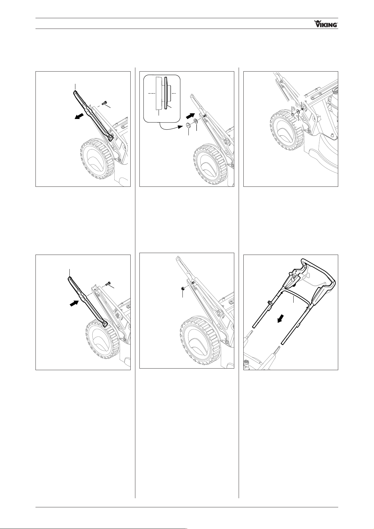
• Remove handlebar 1.
1
- Remove cable anti-kink protection
(see section 02.07.01)
02.11.02 Installing handlebar
height adjustment
- Remove housing cover assembly
(see section 05.02.01)
- Attach housing cover assembly
(see section 05.02.04)
2
1
• Remove cap nut 1 and remove
washer 2.
1
1
2
2
• Pull height adjustment rod 1 to the
left and remove from console 2 on
the right-hand side.
• Pull out height adjustment rod 1 to
the right.
1
2
1
2
• Insert height adjustment rod 1 from
inside into console 2 on left.
• Insert height adjustment rod 1 in
console 2 on right.
• Fit washer 1 onto rod 2 and tighten
cap nut 3 (12-18 Nm).
3
1
2
• Attach handlebar 1.
1
- Install cable anti-kink protection
(see section 02.07.02)
1
1
RA_6360_6375_01 - EN 22
- Handlebar -
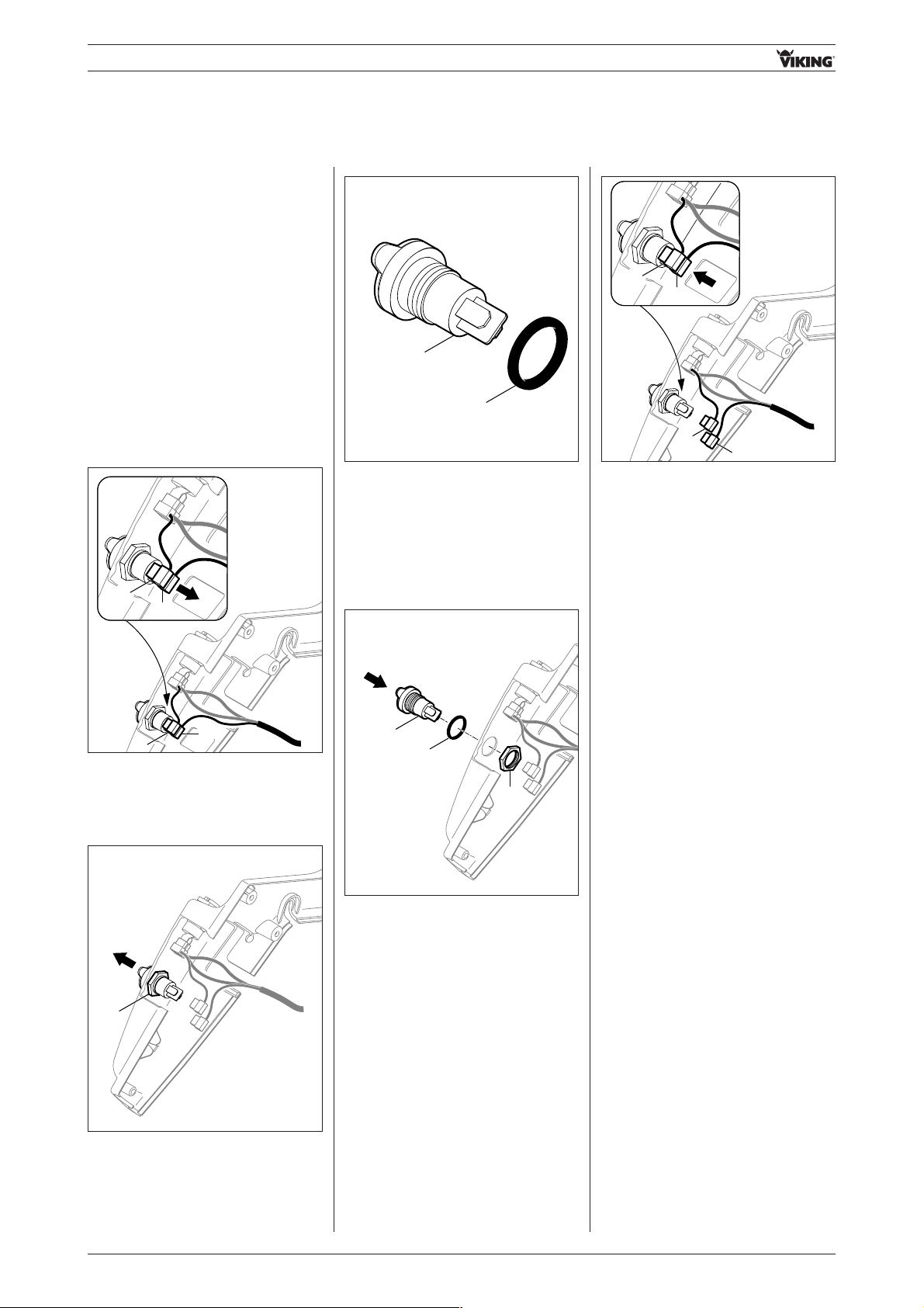
02.12 Replacing charging socket
02.12.01 Removing charging socket
02.12.02 Installing charging socket
• Detach connection cables 1 (red), 2
(black).
1
2
2
1
- Remove inside left housing half
(see section 02.03.03)
- Attach inside left housing half
(see section 02.04.03)
- Disconnect battery
(see section 13.01.01)
- Connect battery
(see section 13.02.02)
1
• Remove nut 1 and remove charging
socket from housing half.
1
2
• Remove sealing ring 1 from
charging socket 2.
2
1
2
1
• Attach connection cables 1 (red),
2 (black) (polarity is indifferent).
1
2
3
• Fit sealing ring 1 onto charging
socket 2.
• Insert charging socket 2 from
outside through opening in housing
half.
• Tighten nut 3 (hand-tight, 1-2 Nm).
RA_6360_6375_01 - EN23
- Handlebar -
1
3
2
• Remove nut 1 and remove ignition
lock 2 together with toothed disk 3
from housing half.
• Detach connection cables 1, 2.
1 2
1
2
02.13.02 Installing ignition lock
1
2
3
• Insert ignition lock 1 together with
toothed disk 2 from inside through
opening in housing half.
• Tighten nut 3 (with convex side
facing outwards) (hand-tight,
1-2 Nm).
- Attach inside left housing
half (see section 02.04.03)
- Connect battery
(see section 13.01.02)
1
2
1
2
• Attach connection cables 1, 2
(polarity is indifferent).
02.13 Replacing ignition lock
02.13.01 Removing ignition lock
- Disconnect battery
(see section 13.01.01)
- Remove inside left housing half
(see section 02.03.03)
RA_6360_6375_01 - EN 24
- Control bars and levers -
03.01 Replacing wheel drive
control bar
03.01.01 Removing wheel drive
control bar
- Remove inside left housing half
(see section 02.03.03)
03.02 Replacing motorstop control bar
03.02.01 Removing motorstop control bar
- Remove inside right housing half
(see section 02.03.01)
• Remove cable support 1.
- Remove inside left housing half
(see section 02.03.03)
03.01.02 Installing wheel drive control bar
- Attach inside left housing half
(see section 02.04.04)
03. Control bars and levers
1
• Detach motorstop cable 1 from
control bar 2.
1
2
• Press motorstop control bar 1
together at both sides and detach
from handlebar.
1
RA_6360_6375_01 - EN25
- Control bars and levers -
03.02.02 Installing motorstop control bar
• Press control bar 1 together and
insert in recesses A in handlebar.
- Attach inside right housing half
(see section 02.04.02)
- Attach inside left housing half
(see section 02.04.03)
1
A
1
A
1
• Attach motorstop cable 1 to control
bar 2.
1
2
• Fit motorstop cable 1 in cable
support 2 and insert cable support
into outside left housing half.
2
1
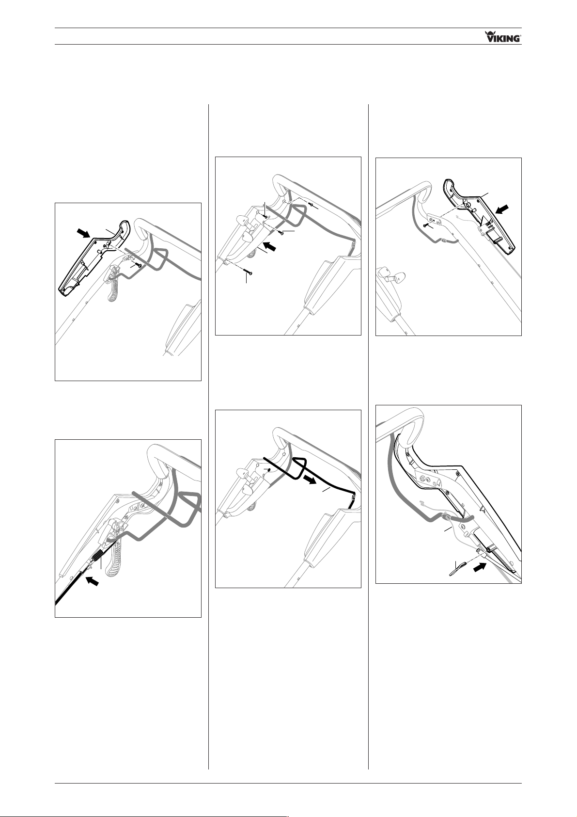
03.03 Replacing blade
stop / Quick-Start
control bar
03.03.01 Removing blade
stop / Quick-Start
control bar
- Remove inside right housing half
(see section 02.03.01)
• Press motorstop / Quick-Start
control bar 1 together at both sides
and detach from handlebar.
- Remove inside left housing half
(see section 02.03.03)
1
RA_6360_6375_01 - EN 26
- Control bars and levers -
- Attach inside left housing half
(see section 02.04.03)
- Attach inside right housing half
(see section 02.04.02)
• Remove locking lever 1 from control
bar 2.
12
03.03.02 Installing blade
stop / Quick-Start
control bar
• Fit detent lever 1 onto control bar 2.
12
• Press control bar 1 together and
insert in guides A.
• Engage locking lever 1 in detent
lever 2.
A
1
A
1
1
RA_6360_6375_01 - EN27
- Control bars and levers -
03.04 Replacing blade
clutch / Quick-Start
lever
03.04.01 Removing blade
clutch / Quick-Start
lever
• Detach motorstop / Quick-Start
control bar 1 from handlebar on
right.
- Remove outside right housing half
(see section 02.03.02)
1
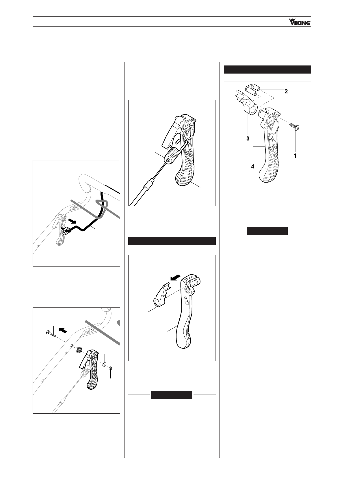
• Remove nut 1 and pull out bolt 2.
Remove blade clutch / Quick-Start
lever 3 with washer 4 and bushing 5.
1
4
2
3
5
03.04.02 Dismantling blade
clutch / Quick-Start
lever
• Detach cable 1 from blade
clutch / Quick-Start lever 2.
1
2
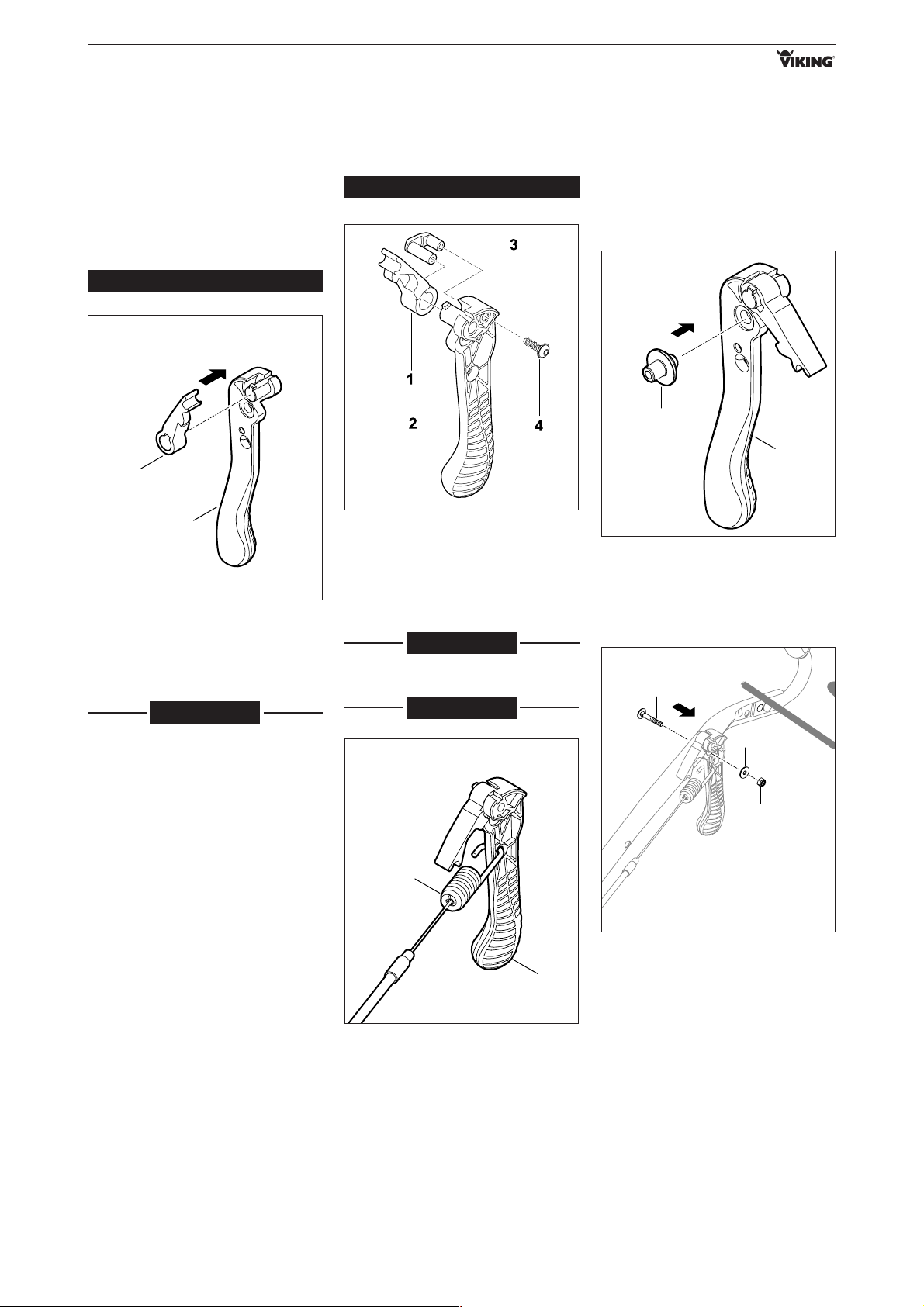
• Detach detent lever 1 from blade
clutch / Quick-Start lever 2.
• Remove 1 screw,
re move reinforcement 2.
Detach detent lever 3 from blade
clutch / Quick-Start lever 4.
1
2
from serial number 4 31 076 057
up to serial number 4 31 076 056
RA_6360_6375_01 - EN 28
- Control bars and levers -
• Fit detent lever 1 onto blade clutch /
Quick-Start lever 2
(ensure correct installation position,
see Fig.). Insert reinforcement 3,
install screw 4 (1-2 Nm).
03.04.03 Assembling blade
clutch / Quick-Start
lever
• Fit detent lever 1 onto blade clutch /
Quick-Start lever 2
(ensure correct installation position,
see Fig.)
1
2
• Attach cable 1 to blade clutch /
Quick-Start lever 2.
1
2
03.04.04 Installing blade clutch /
Quick-Start lever
• Push bushing 1 into blade clutch /
Quick-Start lever 2 and attach to
handlebar.
1
2
• Insert bolt 1 from outside through
handlebar. Fit washer 2 and tighten
nut 3 (1-2 Nm).
3
2
1
03.04.03 (A)
03.04.03 (A)
03.04.03 (A)
from serial number 4 31 076 057
up to serial number 4 31 076 056
RA_6360_6375_01 - EN29
- Control bars and levers -
03.06 Replacing locking lever
03.06.01 Removing locking lever
• Detach motorstop / Quick-Start
control bar 1 from handlebar on
right.
- Remove inside right housing half
(see section 02.03.01)
1
• Remove detent lever 1 from control
bar 2.
12
03.05 Replacing detent lever
03.05.01 Removing detent lever
- Dismantle blade clutch / Quick-Start
lever
(see section 03.04.02)
- Remove blade clutch / Quick-Start
lever
(see section 03.04.01)
03.05.02 Installing detent lever
- Assemble blade clutch / Quick-Start
lever
(see section 03.04.03)
- Install blade clutch / Quick-Start
lever
(see section 03.04.04)
- Attach outside right housing half
(see section 02.04.01)
1
1
A
• Insert motorstop / Quick-Start
control bar 1 into guide A on
handlebar on right.
• Engage locking lever 1 in detent
lever 2.
RA_6360_6375_01 - EN 30
- Control bars and levers -
- Attach inside right housing half
(see section 02.04.02)
03.06.02 Installing locking lever
• Fit detent lever 1 onto control bar 2.
12
1
1
A
• Insert motorstop / Quick-Start
control bar 1 into guide A on
handlebar on right.
• Engage locking lever 1 in detent
lever 2.
03.07 Replacing Vario / three-speed lever
03.07.01 Removing Vario / three-speed lever
• Detach handle 1 from lever 2.
- Remove inside right housing half
(see section 02.03.01)
1
2
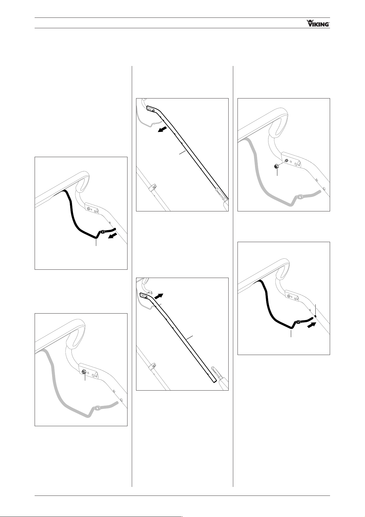
• Detach cable 1 from bracket.
1
Illustrations show version with
blade clutch - (additional
throttle lever)
 Loading...