

Viking FF75 Series User Manual
PnoToFACT* FolJ"*
a
o
.I
L
o
ta
9t
4N
:-tL
l:E
5-
-Et
o
o
=
ffi
! l::
$i
MODEL
g
VIKING
FF75 Series
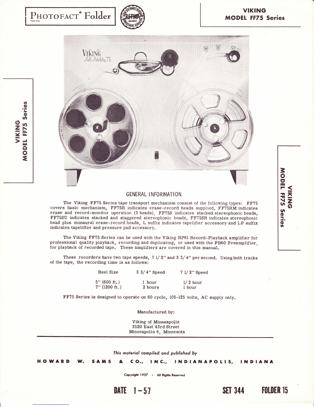
The Viking FF75
covers
erase
FF?5SU indicates
head
indicates
professional
for
of
basic mechanism,
and record-monitor
plus
monaural
tapelifter and
The Viking FF?5
playback
These recorders
the
tape, the
FF?5 Series
quality
recorded
of
recording
Series
I'F?5R indicates
operation
stacked
and
erase-record
pressure pad
Series
playback,
tape.
have
time is as follows:
Reel Size
(600
5"
?"
is
designed
ft.
(1200
GENERAL
tape transport
(3
staggered
can be
recording and
These
two tape speeds,
)
ft"
)
to
operate on 60
heads),
heads, L
stereophonic heads,
accessory.
used
with
amplifiers
3 3/ 4"
I
hour
2 hours
Manufactured
Viking
3520
East 43rd
Minneapolis
I NFORMAT ION
mechanism consist
erase-record heads
FF?5S indicates stacked
suffix indicates
the Viking RPOI Record-Playback
duplicating,
are covered in
7 L/2"
or used with
andS
Speed
of the foiiowing
supplied,
FF?5SR indicates
tapelifter accessory
the
this manual"
persecond"
3/
4"
7
L/ 2"
Speed
2
1/
hour
I hour
cycle, 105-125 volts, AC
by:
of
Minneapolis
Street
6,
Minnesota
supply
types: FF?5
FF?5RM
stereophonic
PB60
Usingboth tracks
indicates
stereophonic
and LP
amplifier
Preamplifier,
only"
heads,
suffix
for
=
o
t'
Itt
r(
tr*
rll-
xz
"o
la
o
:.
o
UI
HOWAnD
W.
SAmS
fhis
moteriol
&
Copytight 1957
lllTt
CO.,
I
-
compiled
ond
published
by
lNC., tNDtANApOItS,
.
All
Righh Rcscrved
57
stt 344
tNDIANA
totDER
l5
T:ff*S
-. @
*
w
Power
Tape
by
Not
higher
_Frequency
Ips
Signal-To-Noise
acteristic
transformer
within
Flutter:
Weight:
Record
Requirement:
Speed: 7-L/
changing
recommended
belt to smaller
than 7500
Response:
Tape speed.
can
or
12
inches
per
0.3
pounds.
11
Head
Characteristics
Track
Gap width
D-C resistance
Inductance
Erase
Head
(if
Track
Gap width
DC
Inductance
Impedance
SPECIFICATIONS
110-volts,
(3
2 ips.
for
cps.)
Ratio:
adversely
be
other
of the
cent or less.
width
used):
width
resistance
3/ 4" ipsspeed
reproduction
50
to
45 db
sources
playback
AC,
groove
15,000
or
better.
affected
strong
of
head
:
60 watts.
is
on motor
of frequencies
plus
cps
(This
location
by
magnetic fields
heads.
or
0.009 in.
0.0015
300
290
0. 125
0.
125
30 mh
10K at
39K at 100kc
008
ohms
mh
ohms
30kc
in.
at
I kc
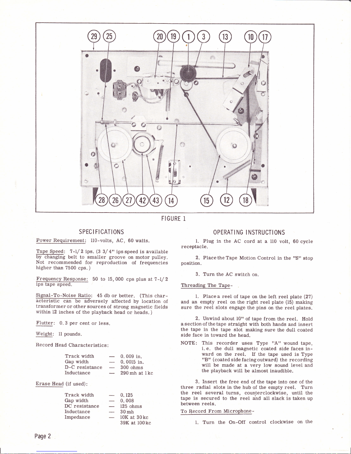
FIGURE
available
pulley.
al7-I/ 2
char-
)
I
receptacle.
position.
Threading The
of
and an empty
sure the
asectionof
the tape in
side face
NOTE: This
three
the reel several
tape
between
To
OPERATI NG
1. Plug in
2. PlacetheTape
3.
Turn
the AC switch
Tape-
1.
Place a
reel
reel
slots engage
2.
Unwind about
thetape straight
the tape
in
toward
recorder
i. e.
the dul1 magnetic
ward
on
(coated
"8"
will
be
playback
the
Insert
3.
radial sl.ots
is secured
reels.
Record
From
Turn the On-Off
l.
NSTRUCTI
I
the AC
reel
cord at a 110
Motion
on.
of tape on
on
the right reel
the
10"
of
tape frorn
with
slot making
the head.
uses Type
reel. If
the
side facingoutward)
made
at
a very
will
be almost inaudible.
the free end
in
the
turns,
of the tape into one of the
hub
counterclockwise,
to the reel
Microphone-
control
ON5
volt, 60
Control
left
the
plate (15)
pins
on the reel
both hands
sure
I'Atr
coated
the
tape used
low
sound
the empty reel. Turn
of
I'Sil
in
the
piate
reel
the reel. Hold
and insert
the dull
wound tape,
side faces in-
is Type
recording
the
level
until the
and
all slack is taken up
clockwise
cycle
stop
(27)
making
plates.
coated
and
the
on
Page 2

amplifier
tubes to warm up.
jack.
used, and
2. Insert
rnicrophone
the
3. Place the Play-Record
position.
4.
(forward)
your
the
cator
peaks
will.
consequent
when
way
To
of
Move the Tape Motion Control to
position.
5. Hold
mouth and
"Volume"
respond.
to
do not
avoid
saturation or overloading of the tape with
microphone about six inches
the
speak
control
Check to be sure that the
cause the eye to close entirely. This
distortion.
the electronic eye indicator
on recording
Record From Radio-
Recordings
three ways:
1.
Place the
peaks.
from a radio may
microphone about
allow about thirty
in a normal voice.
causes the
recording is obtained
Good
seconds
piug
into
the
switch in the
electronic eye i.ndi-
Adjusting
maximum
closes
less
made by one
be
l2!t in front
to
6rr
of the radio speaker. Turn the radio volume
a normal level.
to
tortion. Turn
treble.
cording
Set the
as described under
phone".
as
other sounds may
which as a result will
the
recording
Thistype of recordingmaynot be
Setting
radio
it
high will cause
to
control to
tone
level and
'tTo
picked
be
recorded on the tape.
be
proceed
Record
up by
maxirnum
From
.satisfactory
the microphone
for
I'Miket'
record
rtFt'
the
from
half
than
control
dis-
with re-
Micro-
FI
the
2
GU RE
2. Have a shielded
conductor
on
the
phone plug
other end.
the
voice coil terminals on the
insert the cord
and Volume and Tone controls as
radio
above. Set the
cribed
phone
across the
plug
proceed
Record
volume and tone controls
and
To Record Frory_.Phonograph-
pin
"Radio-Phono"
ceedwiththe
To
ingas
by
under
"To
3. Have
plug
a
on one
radio
into
the
"input
with the recording as described under
From
Microphone". The
may
be
set
1. If the
plug
type
on the
recordingas described
From
Microphone".
Record
"To
Fast
moving the control
From
1.
Use one of the three
Record From Radio"
described under
Forward And Rewind-
High-speed
?:ffi
cable made
on
one end
Connect the
plug
into the
recording level and
Record From
shielded
end
volume control.
jack".
anywhere.
phonograph
pickup
jack.
Set the
Television-
ilTo
forward
knob
and two alligator clips
alligator clips
ilinput
Microphone.'r
with a two conductor
cable
and the other end connected
Set the recording
has
no effect on this
being used
leads,
recording level and
methods described
andproceedwithtHe
Reoord
reverse can be
or
(6)
toward
up with
radio speaker
jackil.
proceed
Insert
position
has a
a
two
across
and
Set the
described
as
des-
phone
the
leveL
and
of the radio
"To
set up
standard
insert it into the
pro-
under
From Microphoneil.
"To
the
Record
under
record-
obtained
head
for
o
=
E
rtt
r(
rri
tt-
de
tn
o
=.o
n
Page
3
from
rewindand all the
Movement
of this
sired reel at a high
position,
this
way
control
speed as
This control
catingadesiredportionof
To Play A Recory!!4g-
l.
the Tape".
fier
Thread tape
2.
Turn control
playback.
to
3, Adjust tlte
desired listening
To Edi.t And Splice
NOTE:
Since
it is
track without
as described
knob
t'Volumet'and
level.
Tape-
impossible to edit
affecting the other,
which are to be
one trdck only.
l. Thetapemaybeeditedby
portions,
Announcements may be inserted between
etc.
Unused
joining
or by
sections of tape can be
selections into another
head for
the
will wind the
long as
primarily
is
arecordingin
under
I'Forward'!
(6)
to
t'Tonetr
edited
should
cutting out
tape on
the
a few
and splice one
be
spliced together
for re-use.
2. Forbestresults, cuttape at
join
ends
and trim off any excessive
Erasing
together
Recorded
Units
matically when unit
desired
to
on the tape follow the
leave
but
counterclockwise
with splicing tape on the
Material-
having erase head the tape
is
in the
erase a recording without
normal recording
tJre
"Volume"
position.
width.
control set at
a slight diagonal,
record
position,
is erased
putting
fast forward.
the de-
control
controls
is in
in 1o-
used
seconds.
rtThreading
and ampli-
for
recordings
limited to
unwanted
sequence.
selections,
glossy
side
auto-
ff it is
anything
procedure,
its extreme
forced away lrom the bracket
be
inchwhenthe Tape
Rewind Drive Adjustment-
Motion
Control
Set rewind drive adjustment
(26)
spring
Tape
adjustment
reel brake
Takeup
No adjustment is
could oceur only because
ure
damage to
Adjustments-
IIead
Head
(A
thinner
cause
adjusted
special
and
justment
retaining
turn
tape,
mum volume oscilloscope,
(Adjust
andadjust.thetwo
indication.
necessary for
is
ing nut and check to
does not bear
Motion Control
must not
adjustment.
Reel Brake-
(18).
pad
on bearing
is in
be changed
)
provided
height is determined by
a very
provided
width.
high frequency
spacer is
of added track
using
indicators. Do
unnecessarily.
To adjust
head face
nut slightly and,
(22)
head
azimuth before completely
To adjust
to obtain
azimuth
use
set-screws alternately
A high
frequency tape
precise
adjustment.
see that
"Stop"
)
not attempt azimuth
parallel
using constant
position
a suitable allen
results. Use of an oscilloscope
essential.
heads
adjustment.
to tape.
The
is indentical. An erase
Merely
procedure
position
for adjustment of binaural
head requires no
the
approximately
is in
"Stop"
(25)
nut
bracket
position.
after setting
necessary.
or
excessive
of
fixed
erase head
for
Each head is
alignment tape
to tape,
providing
meter
or
re-tightening
L/ 64
position.
so that
when
(This
supply
Fail-
wear or
spacers.
(21)
be-
factory
ad-
loosen
frequency
maxi-
indication.
nut.
wrench
for maximum
(at
ieast 7500 cps)
Tighten
no reduction in output
or output
head so face is
retain-
meter
azimuth
paralLel
)
is
ADJUSTMENTS
Removal Of Main Escutcheon-
panel,
To remove front
pensator",
ing screws at
from
place
panel
off
Takeup Drive
loosen
andmovebracketto right, increasing belt
NOTE:
tapelifter
top
tape motion
tape motion control
(24).
Belt-
If
takeup reel
the
the idler bracket
Tootighta belt will cause undesirable
on tape
right as to cause the
to
(if
and
control
during
intothe takeup reel
placed
is
Supply
Control
Reel Brake-
Place Tape Motion
sition, loosen
Blightly
clear of supply
this adjustment
and so
brake
adjust bracket that
reel hub
properly
remove
used), the
bottom
edges
(6).
With motor turned
in forward
(20)
does not drive
mounting screw
play.
Do not move arm
hub when the Tape
in the rewind
Control
bracket
mounting
(2?).
Tighten
made the brake
"tape
four
and remove
position
lower corner
(6)
in
pad
feed com-
panel
retain-
and lift
properly,
(46)
slightly
(13)
tension.
tension
position.
Motion
"Rewind"
screws
(28)
is
screw.
spring will
knob
off,
so far
to dig
po-
(4?)
just
With
Adjustment Of
Assemblies-
NOTE: Pressure
Tapelifter
pad
binaurai or erase
(two
heads). Thetapetifter
is
ever,
Adjust
barelyin
is in
stalled
mounting
necessary to
of
bracket
contact
forward
after front
screw. Bend
and approximately
head
(20)
position,
pad
assembly
pad
holder spring
in
very
path.
noticeableasthepressure
I'Forward"
the
lightly
No appreciable
position.
panel
is in
the
"StopI
Adjustment
The
to
absorb
and average out
adaptable to
(53)
cam
with lifter
position.
panel
bring tapelifter
when Tape
installing
When
(5?)
it may be
(59).
position,
the face of
on
The mounting
place
only
t'Rewind"
or
Tape Feed
Of
purpose
of the
And
Pressure
assemblies can be
record head assemblies
mechanism,
single head unit.
shift rod
on
when Tape
See that
is in
tapelifter
l,/16
Motion Control
(14)
Motion
lifter assembly
place)
is bottomed
support
fingers
parallel
inch above top
(6)
or readjusting
necessary to
With the
flexing
pads
screw is
if the tape
position,
Compensator-
"tape
the slight
tape
pad
heads and
of
the
rest squarely
springs
the
the
are raised to
accessible
motion
feed compensatorl
variations
Pad
used
so that
on
only
how-
it is
Control
(in-
slightly
on
face
to
head
of
rtstop'
is in
pressure
a
motion control
on the
bend
should
lifted
the
the
and
tape
after the
control
is
in tape
if
be
in
is
Page 4
 Loading...