

Viking FDWB301 Installation Manual
Viking Range, LLC
111 Front Street
Greenwood, Mississippi 38930 USA
(662) 455-1200
For product information,
call 1-888-(845-4641)
or visit the Viking Web site at
vikingrange.com
Viking Installation Guide
Professional/Custom Panel
Built-In Full Height Wine Cellar
F20904B EN
(043013))
U
L
U
L
C

2
Table of Contents
Warnings & Important Infor mation_ _ _ _ _ _ _ _ _ _ _ _ _ _ _ _ _ _ _ _ _ _ _ _ _ _ _ _ _ _ _ _ _ _ _ _ _ _ _ _ _ _ _ _ _ _ _ _ _ _ _ _ _ 3
D i m e n s i o n s _ _ _ _ _ _ _ _ _ _ _ _ _ _ _ _ _ _ _ _ _ _ _ _ _ _ _ _ _ _ _ _ _ _ _ _ _ _ _ _ _ _ _ _ _ _ _ _ _ _ _ _ _ _ _ _ _ _ _ _ _ _ _ _ _ _ _ _ _ _ _ _ _ 6
S p e c i f i c a t i o n s _ _ _ _ _ _ _ _ _ _ _ _ _ _ _ _ _ _ _ _ _ _ _ _ _ _ _ _ _ _ _ _ _ _ _ _ _ _ _ _ _ _ _ _ _ _ _ _ _ _ _ _ _ _ _ _ _ _ _ _ _ _ _ _ _ _ _ _ _ _ _ 7
Cutout Dimensions (Professional/Custom) _ _ _ _ _ _ _ _ _ _ _ _ _ _ _ _ _ _ _ _ _ _ _ _ _ _ _ _ _ _ _ _ _ _ _ _ _ _ _ _ _ _ _ _ _ _ 8
Cabinet Information (Professional) _ _ _ _ _ _ _ _ _ _ _ _ _ _ _ _ _ _ _ _ _ _ _ _ _ _ _ _ _ _ _ _ _ _ _ _ _ _ _ _ _ _ _ _ _ _ _ _ _ _ _ _ _ 9
Cabinet Information (Professional w/flush mount trim)_ _ _ _ _ _ _ _ _ _ _ _ _ _ _ _ _ _ _ _ _ _ _ _ _ _ _ _ _ _ _ _ _ _ _ 12
Cabinet Information (Custom Panel) _ _ _ _ _ _ _ _ _ _ _ _ _ _ _ _ _ _ _ _ _ _ _ _ _ _ _ _ _ _ _ _ _ _ _ _ _ _ _ _ _ _ _ _ _ _ _ _ _ _ 1 5
Custom Side Panel Dimensions (Professional/Standard Mount) _ _ _ _ _ _ _ _ _ _ _ _ _ _ _ _ _ _ _ _ _ _ _ _ _ _ _ 18
Custom Side Panel Dimensions (Custom Panel/Professional w/flush mount trim) _ _ _ _ _ _ _ _ _ _ _ 19
C u s t o m D o o r P a n e l D i m e n s i o n s _ _ _ _ _ _ _ _ _ _ _ _ _ _ _ _ _ _ _ _ _ _ _ _ _ _ _ _ _ _ _ _ _ _ _ _ _ _ _ _ _ _ _ _ _ _ _ _ _ _ _ _ 2 0
Door Panel Installation (Custom Panel) _ _ _ _ _ _ _ _ _ _ _ _ _ _ _ _ _ _ _ _ _ _ _ _ _ _ _ _ _ _ _ _ _ _ _ _ _ _ _ _ _ _ _ _ _ _ _ _ 2 1
Custom Wood Facing Dimensions _ _ _ _ _ _ _ _ _ _ _ _ _ _ _ _ _ _ _ _ _ _ _ _ _ _ _ _ _ _ _ _ _ _ _ _ _ _ _ _ _ _ _ _ _ _ _ _ _ _ _ _ 2 2
General Information _ _ _ _ _ _ _ _ _ _ _ _ _ _ _ _ _ _ _ _ _ _ _ _ _ _ _ _ _ _ _ _ _ _ _ _ _ _ _ _ _ _ _ _ _ _ _ _ _ _ _ _ _ _ _ _ _ _ _ _ _ _ _ _ 2 4
Unpacking & Moving _ _ _ _ _ _ _ _ _ _ _ _ _ _ _ _ _ _ _ _ _ _ _ _ _ _ _ _ _ _ _ _ _ _ _ _ _ _ _ _ _ _ _ _ _ _ _ _ _ _ _ _ _ _ _ _ _ _ _ _ _ _ 2 5
Home Security System Connection _ _ _ _ _ _ _ _ _ _ _ _ _ _ _ _ _ _ _ _ _ _ _ _ _ _ _ _ _ _ _ _ _ _ _ _ _ _ _ _ _ _ _ _ _ _ _ _ _ 2 6
Securing Your Wine Cellar _ _ _ _ _ _ _ _ _ _ _ _ _ _ _ _ _ _ _ _ _ _ _ _ _ _ _ _ _ _ _ _ _ _ _ _ _ _ _ _ _ _ _ _ _ _ _ _ _ _ _ _ _ _ _ _ _ _ _ 2 7
K i c k p l a t e I n s t a l l a t i o n _ _ _ _ _ _ _ _ _ _ _ _ _ _ _ _ _ _ _ _ _ _ _ _ _ _ _ _ _ _ _ _ _ _ _ _ _ _ _ _ _ _ _ _ _ _ _ _ _ _ _ _ _ _ _ _ _ _ _ _ _ _ _ _ 2 9
Door Stop/Hinge Adjustment _ _ _ _ _ _ _ _ _ _ _ _ _ _ _ _ _ _ _ _ _ _ _ _ _ _ _ _ _ _ _ _ _ _ _ _ _ _ _ _ _ _ _ _ _ _ _ _ _ _ _ _ _ _ _ _ 3 0
Performance Checklist _ _ _ _ _ _ _ _ _ _ _ _ _ _ _ _ _ _ _ _ _ _ _ _ _ _ _ _ _ _ _ _ _ _ _ _ _ _ _ _ _ _ _ _ _ _ _ _ _ _ _ _ _ _ _ _ _ _ _ _ _ _ 3 1
Service & Registration_ _ _ _ _ _ _ _ _ _ _ _ _ _ _ _ _ _ _ _ _ _ _ _ _ _ _ _ _ _ _ _ _ _ _ _ _ _ _ _ _ _ _ _ _ _ _ _ _ _ _ _ _ _ _ _ _ _ _ _ _ _ _ 3 2
3
IMPORTANT–Please Read and Follow!
• Make sure that incoming voltage is the same
as unit rating. An electric rating plate
specifying voltage, frequency, wattage,
amperage, and phase is attached to the
product.
• To reduce the risk of fire, electric shock, or
injury to persons, installation work and
electrical wiring must be done by qualified
people in accordance with all applicable
codes and standards, including fire-rated
construction.
• The installer should leave these instructions
with the consumer who should retain them
for local inspector’s use and for future
reference.
It is your responsibility to:
• Comply with installation specifications and
dimensions
• Properly install unit
• Remove any moldings or decorative panels
that prevent the unit from being serviced
• Assure that floor will support unit, door
panels and contents (approximately 1200
lbs/540 kg)
• Provide a properly grounded electrical outlet
• Assure that location will permit appliance
doors to open 90° minimum
Your safety and the safety of others is
very important.
We have provided many important safety
messages in this manual and on your
appliance. Always read and obey all
safety messages.
This is the safety alert symbol. This
symbol alerts you to hazards that
can kill or hurt you and others.
All safety messages will be preceded by the
safety alert symbol and the word“DANGER”
or “WARNING.” These words mean:
DANGER
Hazards or unsafe practices which
WILL result in severe personalinjury
or death.
WARNING
Hazards or unsafe practices which
COULD result in minor personal injury
or property damage.
All safety messages will identify the
hazard, tell you how to reduce the chance
of injury, and tell you what can happen if
the instructions are not followed.
CAUTION
Hazards or unsafe practices
which COULD result in severe
personal injury or death.
4
IMPORTANT–Please Read and Follow!
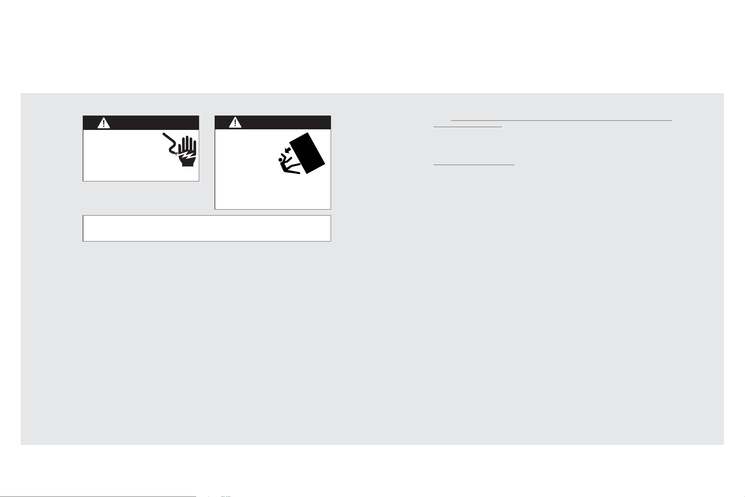
WARNING
TIP OVER HAZARD
Appliance is top heavy
and tips easily when
not completely
installed. Keep doors
closed until appliance
is completely installed
and secured per installation instructions.
Use two or more people to move and
install appliance. Failure to do so can
result in death or serious injury.
WARNING
ELECTRICAL SHOCK
HAZARD
Disconnect power or turn
power disconnect switch to
OFF position before removing
top grille. Failure to do so can
result in death or electrical shock.
Most of the unit’s weight is at the top. Extra care is needed when moving the unit to prevent
tipping. Use cardboard shipping material or plywood under unit until it is installed in the
operating position to protect floor surface.
5
IMPORTANT–Please Read and Follow!
A GFI
shall be used if required by NFPA-70 (National Electric Code), federal/state/local
laws, or local ordinances.
• The required use of a GFI is normally related to the location of a receptacle with respect to
any significant sources of water or moisture.
• Viking Range Corporation will NOT warranty any problems resulting from GFI outlets which
are not installed properly or do not meet the requirements below.
If the use of a GFI is required
, it should be:
• Of the receptacle type (breaker type or portable type NOT recommended)
• Used with permanent wiring only (temporary or portable wiring NOT recommended)
• On a dedicated circuit (no other receptacles, switches or loads in the circuit)
• Connected to a standard breaker of appropriate size (GFI breaker of the same size NOT
recommended)
• Rated for Class A (5 mA +/- 1 mA trip current) as per UL 943 standard
• In good condition and free from any loose-fitting gaskets (if applicable in outdoor situations)
• Protected from moisture (water, steam, high humidity) as much as reasonably possible
6
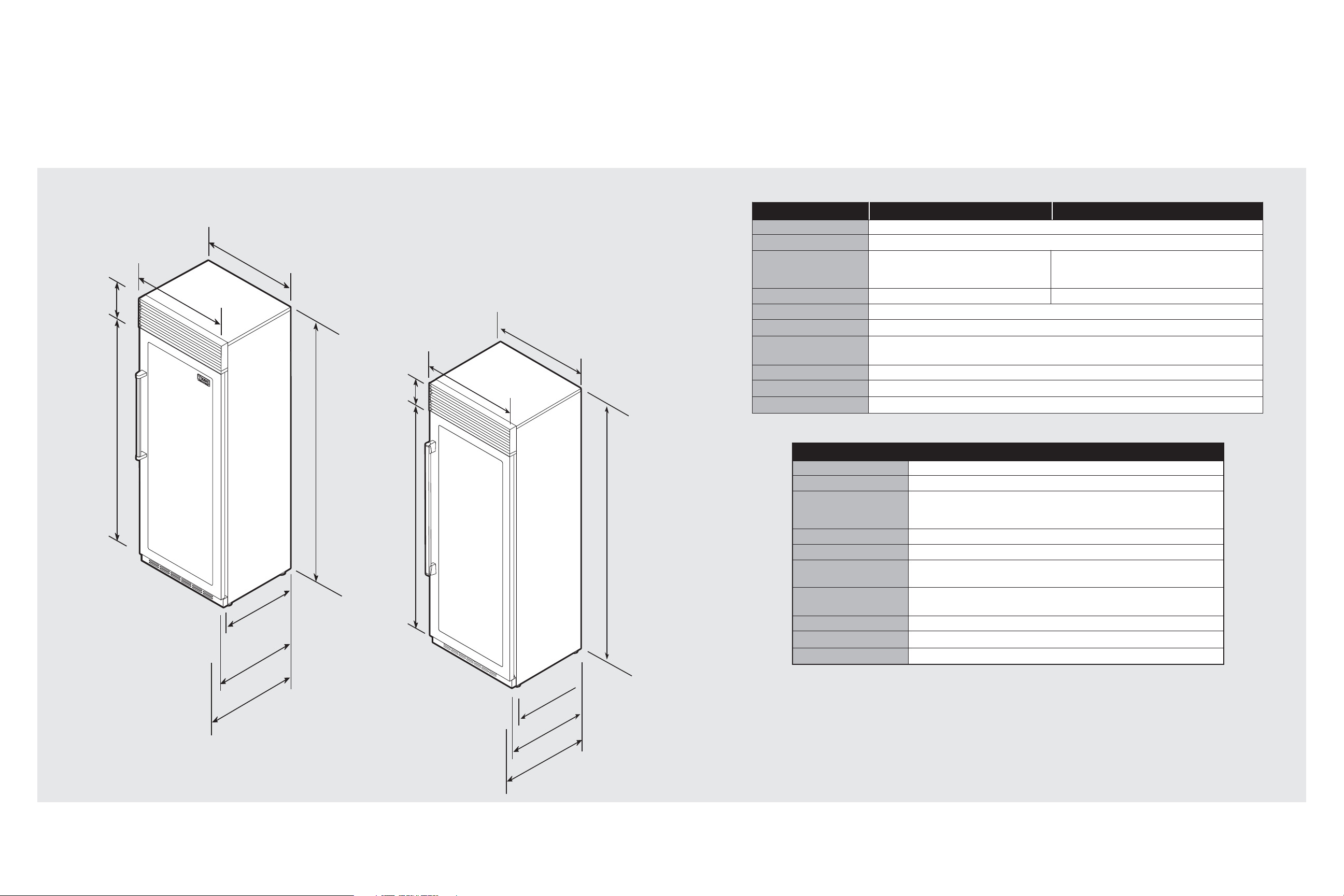
Dimensions
30” Professional
30” Custom
7
Specifications
Description VCWB301/Standard Mount VCWB301/Flush Mount
Overall width 30” (76.2 cm)
Overall height from bottom 82-3/4” (210.2 cm) min. to 84-1/16” (213.5 cm) max.
Overall depth from rear To rear edge of side trim: 22-3/16” (56.4 cm)
To front of door: 24-1/32” (61.0 cm)
To end of handle bracket: 27” (68.6 cm)
23-13/16” (60.5 cm)
To front of door: 24-1/32” (61.0 cm)
To end of handle bracket: 27” (68.6 cm)
Cutout width 29-5/8” (75.2 cm) 30” (76.2 cm)
Cutout height 82-7/8” (210.5 cm) min. to 84-1/16” (213.5 cm) max.
Cutout depth 24” (61.0 cm) min.
Electrical requirements 115 volt, 60 Hz, 15 amp dedicated circuit; 3-wire cord with
grounded 3-prong plug attached to product
Maximum amp usage 2.3 amps
Overall capacity 150 bottles
Approximate shipping w eight 560 lbs. (252 kg)
NOTE: Flush Mount Trim (PBIRFTKSS) purchased
separately.
Description FDWB301
Overall width 30” (76.2 cm)
Overall height from bottom 82-3/4” (210.2 cm) min. to 84-1/16” (213.5 cm) max.
Overall depth from rear To front edge of side trim: 23-13/16” (60.5 cm)
To front edge of cabinet side trim: 24-3/4” (62.9 cm)
To front edge of door handle: Varies
Cutout width 30” (76.2 cm)
Cutout height 82-7/8” (210.5 cm) min. to 84-1/16” (213.5 cm) max.
Cutout depth 25” (63.5 cm) - can be installed in 24” (61.0) cm deep openings; door faces
and top grille will protrude 3/4” (1.9 cm) into room.
Electrical requirements 115 volt, 60 Hz, 15 amp dedicated circuit; 3-wire cord with
grounded 3-prong plug attached to product
Maximum amp usage 2.3 amps
Overall capacity 150 bottles
Approximate shipping w eight 560 lbs. (252 kg)
9-5/16”
(23.6 cm)
70”
(177.5 cm)
30”
(76.2 cm)
22-3/16” (56.4 cm)
23-13/16”
29”
(73.7cm)
Standard Mount/
(60.5 cm)
Flush Mount
24-1/32”
(61.0 cm)
27”
(68.6 cm)
82-7/8”
(210.5 cm)
min.
to
84-1/16”
(213.5 cm)
max.
9-5/8”
(24.4 cm)
70”
(177.5 cm)
30”
(76.2 cm)
29”
(73.7 cm)
23-13/16”
(60.5 cm)
24-3/4”
(62.9 cm)
82-7/8”
(210.5 cm)
min.
to
84-1/16”
(213.5 cm)
max.
VARIES
8
Cutout Dimensions (Professional/Custom)
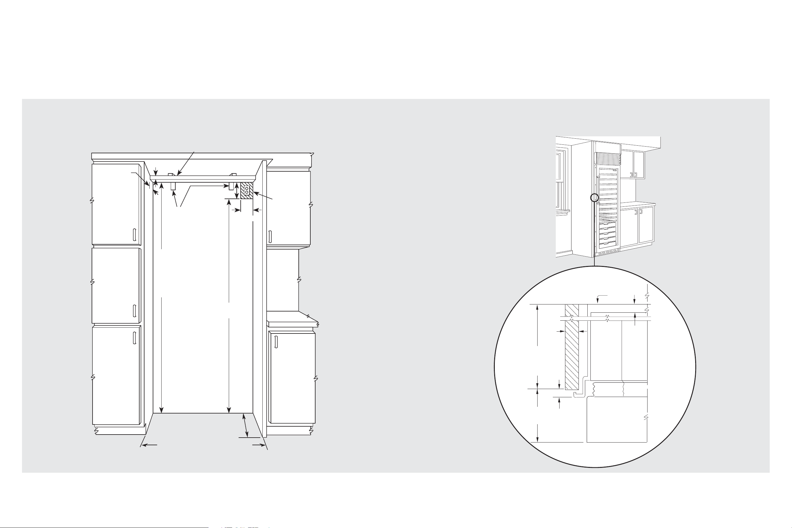
9
1-1/2”
(3.8 cm)
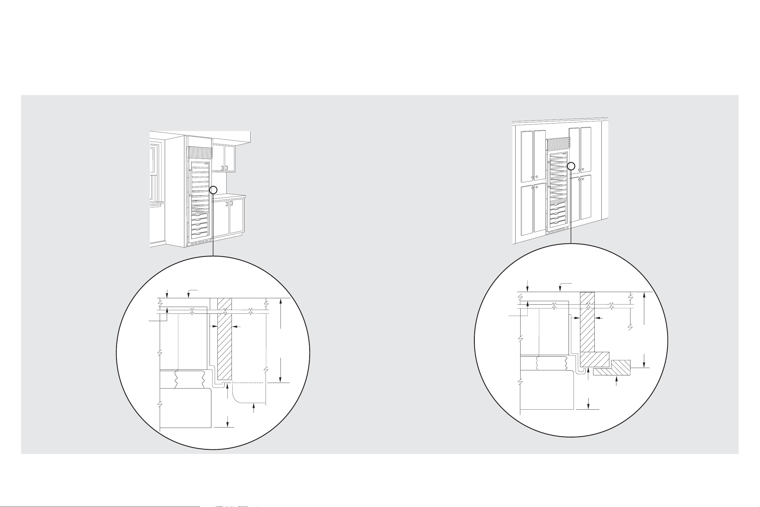
Cabinet Information (Professional)
Professional models fit “semi-flush” in standard 24” (61.0 cm) deep cabinet openings. The door
face protrudes 2-1/16” (5.2 cm) from the cabinet face. The handle protrudes an additional 2-1/2”
(6.4 cm) into the room.
TOP VIEW
2” x 4” Mounting Board [1-1/2” (3.8 cm) x 3-1/2” (8.9 cm)]
Attached to anti-tip mounting bracket
Note: If unit is installed deeper than 24” (61.0 cm), then
shim behind anti-tip bracket thickness by the same amount
1-1/2”
1-1/2”
(3.8 cm)
(3.8 cm)
3-1/2”
(8.9 cm)
8-1/4”
(20.9 cm)
Anti-tip mounting
brackets attached
to wall studs
84-1/16” (213.5 cm) max.
anti-tip board and opening
height
to
82-7/8” (210.5 cm) min.
anti-tip board and opening
height
4”
(10.2 cm)
Electrical
outlet
location
Wall
73-3/4”
(187.3 cm)
24” (61.0 cm) Professional
25” (63.5 cm) Custom Panel*
29-5/8” (75.2 cm) Standard Mount
30” (76.2 cm) Flush Mount Only
*Custom Panel models fit flush in 25”
(63.5 cm) deep cabinet openings.
They can be installed in standard 24”
(61.0 cm) deep openings. The door
faces and top grille will protrude 3/4”
(1.9 cm) into the room.
24”
(61.0 cm)
standard
cabinet
depth
2-1/16”
(5.2 cm)
offset
3/4”
(1.9 cm)
full end
panel
5/16”
(0.8 cm)
1-13/16”
(4.6 cm)
Door
10
Cabinet Information (Professional)
Professional models fit “semi-flush” in standard 24” (61.0 cm) deep cabinet openings. The door
face protrudes 2-1/16” (5.2 cm) from the cabinet face. The handle protrudes an additional 2-1/2”
(6.4 cm) into the room.
TOP VIEW
Cabinet Information (Professional)
TOP VIEW
111213
Wall
Wall
1-13/16”
(4.6 cm)
space if 24”
(61.0 cm)
standard cabinet
depth is used
Door
2-1/16”
(5.2 cm)
offset
3/4”
(1.9 cm)
full end
panel
Countertop
overhang
24”
(61.0 cm)
standard
cabinet
depth
1-13/16”
(4.6 cm)
space if 24”
(61.0 cm)
standard cabinet
depth is used
Door
2-1/16”
(5.2 cm)
offset
3/4”
(1.9 cm)
full end
panel
Partial overlay
cabinet door
24”
(61.0 cm)
standard
cabinet
depth
 Loading...