

Page 1
Technical Data Manual
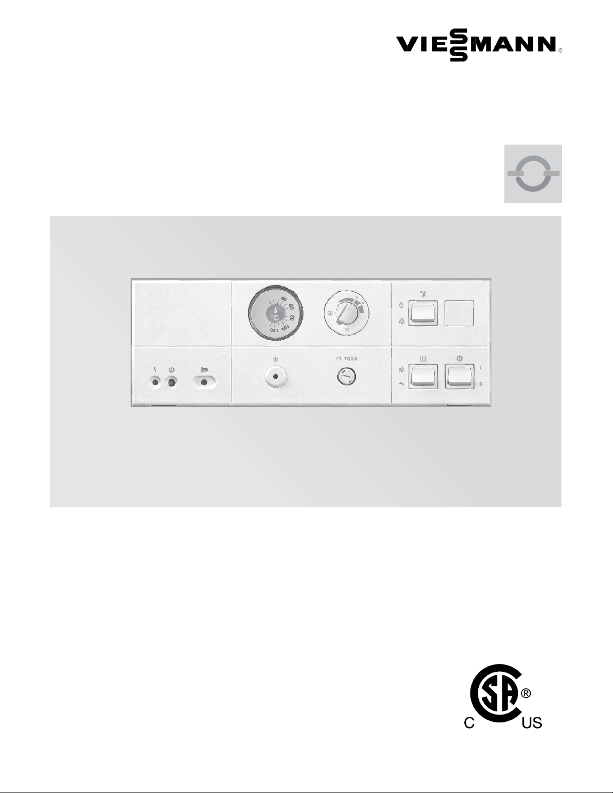
VITOTRONIC 100
Digital boiler control unit
for modulating temperature heating systems
Vitotronic 100
Model KW10B, Part No. 7834 238
Digital boiler control
With outdoor reset control
For heating systems with one modulating temperature
heating circuit (without mixing valve)
With analog boiler water temperature display
Integrated pump connections
Viessmann quick-connect plug-in system
OpenTherm functionality
5604 122 v1.0 07/2011
Certified as a component
part for Viessmann boilers
Page 2
Product Information
Vitotronic 100, KW10B Technical Data
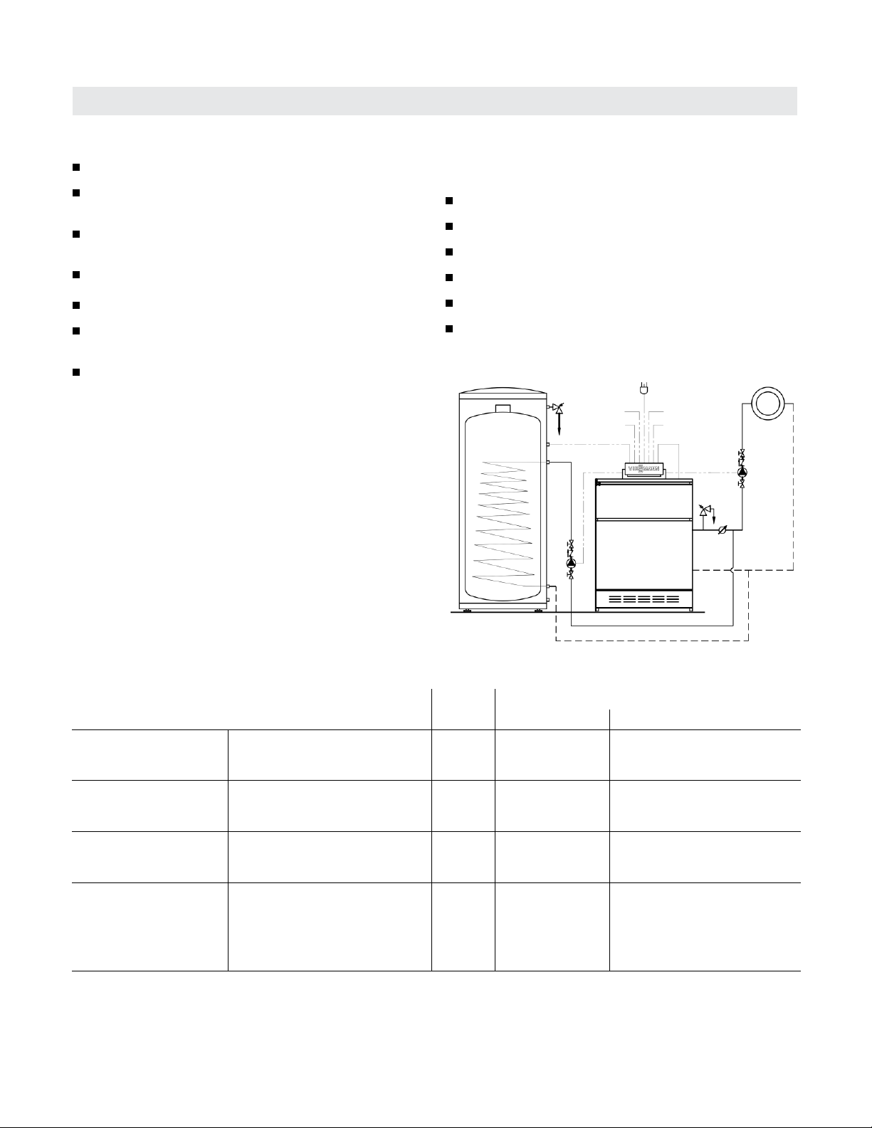
The benefits at a glance:
digital boiler control
space heating circuit controlled by room thermostat
and outdoor reset logic
single-stage or two-stage boiler control
(depending on burner)
integrated diagnostic system
built-in boiler low temperature protection
short assembly time and start-up due to diagnostic
and wire terminals
digital boiler control:
- for single-boiler systems
- outdoor reset control
- for heating circuits without mixing valves
- for single-stage or two-stage burner
- with analog temperature display
- with integrated diagnostic system
Standard equipment:
Vitotronic 100, Model KW10B with;
adjustable fixed high limit
power supply cord
outdoor temperature sensor
boiler temperature sensor
DHW temperature sensor
120VAC boiler pump and DHW pump outputs
Application
In conjunction with the following Viessmann boiler
Boiler Model and Series
Oil-fired hot water
heating boiler with
power burner
Oil-/Gas-fired hot water
heating boiler with
power burner
Atmospheric gas-/
propane-fired hot water
heating boiler
Atmospheric gas-fired
hot water heating boiler
2
Vitorond 100 Oil 104º F (40º C)
Vitola 200 Oil/Gas
Vitogas 050, RS Series (single-/
two-stage)
Vitogas 100, GS1 Series,
up to 240 MBH/70 kW
Vitogas 100, GS10 Series,
up to 380 MBH/111 kW
Fuel Minimum boiler water temperature
without low limit with low limit (average temp.)
x
Gas 120º F (49º C)
Gas
Gas
104º F (40º C)
120º F (49º C)
5604 122 v1.0
Page 3

Vitotronic 100, KW10B Technical Data
Structure and Operation
Functionality Overview
- outdoor reset functionality with the ability to connect
to room thermostat demand type connection
- reset curve adjustments with rotary dial settings as
well as WWSD adjustments
- integrated DHW control and pump output adjustable
set point with rotary dial settings
- operational DHW settings with DIP switch settings;
- DHW priority
- DHW post purge time
- relay test functionality
pumps: DHW and boiler
burner: 1st and 2nd stage
alarm output
- LON addressing with rotary dial settings
- multi-boiler operation when used in conjunction with
Vitocontrol-S MW1 cascade control
- minimum boiler protection
- two stage burner operation
- compiled fault output (dry contact) and LED indicators
- 0-10VDC BMS set point control
Options
With optional OT thermostat via digital two wire
communication, providing local or remote user interface
- DHW set point adjustment and time scheduling
- outdoor reset adjustment and time scheduling
- slope, daytime/night time settings
- boiler status and temperature displayed on thermostat
- can be installed within living space or adjacent to boiler
Modular structure
The control unit consists of:
System ON/OFF switch, analog temperature display and
override switch.
- adjustable high limit (type RAK 51.1/3382, Mfg. Etheco
or type TR 97.55180.251, Mfg. EGO)
- fixed high limit (type RAK 75.4/3412, Mfg. Etheco
or type STW 56.10525.400, Mfg. EGO)
- electronic circuit board with power supply and
integrated outdoor reset function
- integrated diagnostic system (power, burner call and
fault indicators)
Boiler-specific functions
The Vitotronic 100 control unit controls the boiler
temperature according to heat demand input (room
thermostat connections) or the calculated outdoor reset
set point.
Boiler water temperature is limited through the adjustable
aquastat. Minimum boiler water temperature protection is
achieved with the built-in pump aquastat and the outdoor
reset control.
Electronic boiler control
- single boiler systems
- heating circuits without mixing valves
- single and two stage burners
- anolog temperature display
With optional LON communication module
- communications to Vitotronic 050, HK1M mixing valve
controls
- communications to Vitocontrol-S, MW1 cascade control
- enables connection with extension output module
- BACnet communications utilizing Versatronik 505,
BACIP
5604 122 v1.0
3
Page 4

Structure and Operation (continued)
Heating curve
BOILER TEMPERATURE
Vitotronic 100, KW10B Technical Data
OUTDOOR TEMPERATUIRE
Technical data
Power: 120 VAC, 1 Phase, 60 Hz, 15A pre-fuse
Burner switching capacity: 120 VAC, 2.5A (full load)
Room thermostat: 24 VAC
Anticipator setting: 0.1 A
Fixed high limit: 230° F (110° C) max. (fixed)
Adjustable high limit: 167° F to 239° F max.
(75° C to 115° C) max. (adjustable)
Boiler & DHW Pump output: 120 VAC, 1 Phase, 60 Hz,
3A (full load)
Outdoor temperature sensor: 5k Ohms at 77° F (25° C)
max. wire length up to
95 ft. (35 m)
Boiler temperature sensor: 10K
DHW temperature sensor: 10K
Main fuse: 6.3A
Main pump output fuse: 6.25A
Certification: CSA certified in conjunction with Viessmann
boilers
4
5604 122 v1.0
Page 5

Vitotronic 100, KW10B Technical Data
Features
Function Description KW10B KK10 KW10 KK10LON
120VAC Power connection Control Power
Boiler Pump 120V output for boiler pump
DHW Pump 120V output for DHW pump
Burner connection Harness connection for burner
Low Water Cut-off Powers LWCO device
Outdoor Temperature Sensor 5K ohm sensor
Boiler Temperature Sensor 10K ohm sensor
DHW Temperature Sensor 10K ohm sensor
TT Stage 1 Call for heat first stage
TT Stage 2 Call for heat second stage
OpenTherm Communication OT connection for OT enabled room
thermostat/device
Fault Output Compiled Fault Indication Dry Contact
0-10VDC Input/Ext Demand Coded function either 0-10VDC or
external demand
Lon Communications Daisy-chained LON connection when
optional LON board installed
Override Switch Mounted on face of control
Diagnostic LED Sensor Flash Flash based on sensor issue
Power Switch
Pump Aquastat min. temp. control
Electronic minimum temperature control
External pump module
Integrated pump boiler and DHW pump
connection
Relay Test
Selectable boiler pump operation based
on TT demand or continuous operation
Electronic DHW set point control
DHW Priority Override Timer With TT demands only
Front Panel mounted AHL and FHL
Front panel mounted analog
temperature gauge
All relays with sockets with locking tabs
Field replaceable motherboard no hardwired PCB connections
Second Stage Second stage burner demand*
5604 122 v1.0
5
Page 6

Vitotronic 100, KW10B Technical Data
Connections
Function Connection Description
120VAC power connection 40 control power
Boiler pump 20 120VAC output for boiler pump
DHW pump 21 120VAC output for DHW pump
Burner connection 41 harness connection for burner
Second stage 191 second stage burner demand
Low water cut-off LWCO powers LWCO device
Outdoor temperature sensor 1 5K ohm sensor
Boiler temperature sensor 3 10K ohm sensor
DHW temperature sensor 5 10K ohm sensor
TT stage 1 call for heat first stage
TT stage 2 call for heat second stage
OpenTherm communication OT OT connection for OT enabled room thermostat/device
Fault output AL Compiled fault indication
0-10VDC input/ext demand A1 coded function either 0-10VDC or external demand
LON communications C1/C2 Daisy-chained LON connection when optional LON board installed
Terminal connections
- screw-type connection
- RAST-5 quick connects
- Low voltage sensor and communication screw type
connections
6
5604 122 v1.0
Page 7

Vitotronic 100, KW10B Technical Data
Accessories
Boiler water / DHW temperature sensor
Cable length: 5.2 ft. (1.6 m), ready to plug in.
Maximum ambient temperature
- at operation: (in rooms and installation sites with
normal ambient conditions) 32 to 104 ºF (0 to 40 ºC)
- when storing or transporting:
-4 to +149 ºF (-20 to +65 ºC)
Minimum boiler temperature protection and freeze-up
- controlled by electronic boiler temperature sensor
- DIP switch enabled/disabled
Outdoor temperature sensor
Installation site: North or northwest side of building
6.6 to 8.2 ft. (2 to 2.5 m) above ground,
for multi-storey buildings mount sensor
on upper half of second storey.
Connection: 2-wire cable, cable length 1000 ft. (300 m)
with a wire size of min. AWG 16 copper.
The cable to the outdoor sensor must not be laid near line
voltage wiring (120/240 V).
Maximum ambient temperature at operation, when storing
or transporting:- 40 to +158 ºF (- 40 to +70 ºC)
5604 122 v1.0
7
Page 8

Vitotronic 100, KW10B Technical Data
Quick Reference
°C °F
-40 -40
-35 -31
-25 -13
-20 -4
-18 0
-16 +3
-14 +7
-12 +10
-10 +14
-9 +16
-8 +18
-7 +19
-6 +21
-5 +23
-4 +25
-3 +27
-2 +28
-1 +30
0 +32
+1 +34
+2 +36
+3 +37
+4 +39
+5 +41
+6 +43
+7 +45
+8 +46
+9 +48
+10 +50
+12 +54
+14 +57
+16 +61
+18 +64
+20 +68
+25 +77
+30 +86
+35 +95
+40 +104
+50 +122
+60 +140
+70 +158
+80 +176
+90 +194
+100 +212
+110 +230
Printed on environmentally friendly
(recycled and recyclable) paper.
Technical information subject to change without notice.
Viessmann Manufacturing Company (U.S.) Inc.
45 Access Road
Warwick, Rhode Island · 02886 · USA
1-800-288-0667 · Fax (401) 732-0590
www.viessmann-us.com · info@viessmann-us.com
Viessmann Manufacturing Company Inc.
750 McMurray Road
Waterloo, Ontario · N2V 2G5 · Canada
1-800-387-7373 · Fax (519) 885-0887
www.viessmann.ca · info@viessmann.ca
5604 122 v1.0
 Loading...