


 Loading...
Operator’s Manual
AVEA
Ventilator Systems
L2786 Rev. D

ii
AVEA Ventilator Systems
This page intentionally left blank.
L2786

Operator’s Manual iii
Revision History
|
Date |
Revision |
Pages |
Changes |
|
September 2005 |
A |
All |
Release |
|
May 2006 |
B |
1-1, 1-4, 2-7, 2-10 |
Removed references to the Plus model |
|
|
|
2-12 |
Removed “non-operational” from figure 2-19 |
|
|
|
3-16, 3-18, 3-21, 3-33, |
Added a note regarding the setting of Peak |
|
|
|
3-34, 3-35, |
Inspiratory Pressure |
|
|
|
5-3 |
Added Ppeak to the list of alert messages |
|
December 2006 |
C |
2-31 |
Updated the Primary Controls table |
|
|
|
2-36 |
Added NCPAP to the troubleshooting table |
|
|
|
3-33 |
Updated the Rate specification |
|
|
|
5-1 to 5-7 |
Added the chapter “Infant NCPAP” |
|
February 2007 |
D |
4-7 |
Updated the figure and added a description of the |
|
|
|
|
balloon size and type selection |
|
|
|
4-25 |
Added a note regarding the date and time |
|
|
|
|
|
|
|
|
|
|
|
|
|
|
|
|
|
|
|
|
|
|
|
|
|
|
|
|
|
|
|
|
|
|
|
|
|
|
|
|
|
|
|
|
|
|
|
|
|
|
|
|
|
|
|
|
|
|
|
|
|
|
|
|
|
|
|
|
|
|
|
|
|
|
|
|
|
|
|
|
|
|
|
|
|
|
|
|
|
|
|
|
|
|
|
|
|
|
|
|
L2786

iv
AVEA Ventilator Systems
Warranty
THE AVEA® ventilator systems are warranted to be free from defects in material and workmanship and to meet the published specifications for Two (2) years or 16,000 hours, whichever occurs first.
The liability of VIASYS Respiratory Care Inc. (referred to as the Company) under this warranty is limited to replacing, repairing or issuing credit, at the discretion of the Company, for parts that become defective or fail to meet published specifications during the warranty period; the Company will not be liable under this warranty unless (A) the Company is promptly notified in writing by Buyer upon discovery of defects or failure to meet published specifications; (B) the defective unit or part is returned to the Company, transportation charges prepaid by Buyer; (C) the defective unit or part is received by the Company for adjustment no later than four weeks following the last day of the warranty period; and (D) the Company’s examination of such unit or part shall disclose, to its satisfaction, that such defects or failures have not been caused by misuse, neglect, improper installation, unauthorized repair, alteration or accident.
Any authorization of the Company for repair or alteration by the Buyer must be in writing to prevent voiding the warranty. In no event shall the Company be liable to the Buyer for loss of profits, loss of use, consequential damage or damages of any kind based upon a claim for breach of warranty, other than the purchase price of any defective product covered hereunder.
The Company warranties as herein and above set forth shall not be enlarged, diminished or affected by, and no obligation or liability shall arise or grow out of the rendering of technical advice or service by the Company or its agents in connection with the Buyer's order of the products furnished hereunder.
Limitation of Liabilities
This warranty does not cover normal maintenance such as cleaning, adjustment or lubrication and updating of equipment parts. This warranty shall be void and shall not apply if the equipment is used with accessories or parts not manufactured by the Company or authorized for use in writing by the Company or if the equipment is not maintained in accordance with the prescribed schedule of maintenance.
The warranty stated above shall extend for a period of TWO (2) years from date of shipment or 16,000 hours of use, whichever occurs first, with the following exceptions:
1.Components for monitoring of physical variables such as temperature, pressure, or flow are warranted for ninety (90) days from date of receipt.
2.Elastomeric components and other parts or components subject to deterioration, over which the Company has no control, are warranted for sixty (60) days from date of receipt.
3.Internal batteries are warranted for ninety (90) days from the date of receipt.
The foregoing is in lieu of any warranty, expressed or implied, including, without limitation, any warranty of merchantability, except as to title, and can be amended only in writing by a duly authorized representative of the Company.
L2786

Operator’s Manual v
Contents
Revision History........................................................................................................ |
iii |
|
Warranty .................................................................................................................... |
|
iv |
Notices ...................................................................................................................... |
|
vii |
Safety Information .................................................................................................... |
ix |
|
Equipment Symbols ................................................................................................. |
xi |
|
Chapter 1 |
Introduction......................................................................................... |
1-1 |
Some AVEA Features .................................................................................................................. |
1-2 |
|
Chapter 2 Unpacking & Setup............................................................................. |
2-1 |
|
Ventilator Assembly & Physical Setup....................................................................................... |
2-1 |
|
Setting Up the Front of the Ventilator ........................................................................................ |
2-3 |
|
Front Panel Connections............................................................................................................. |
2-7 |
|
Setting Up the Rear of the Ventilator........................................................................................ |
2-14 |
|
User Verification Test ................................................................................................................ |
2-26 |
|
AVEA User Verification Test Checklist .................................................................................... |
2-33 |
|
AVEA Troubleshooting.............................................................................................................. |
2-34 |
|
Chapter 3 |
Ventilator Operation ........................................................................... |
3-1 |
Membrane Buttons and LEDs ..................................................................................................... |
3-1 |
|
Patient Setup ................................................................................................................................ |
3-9 |
|
Ventilation Setup........................................................................................................................ |
3-10 |
|
Setting the Ventilation Breath Type and Mode........................................................................ |
3-14 |
|
Primary Breath Controls............................................................................................................ |
3-31 |
|
Advanced Settings..................................................................................................................... |
3-37 |
|
Independent Lung Ventilation (ILV).......................................................................................... |
3-44 |
|
Chapter 4 Monitors, Displays and Maneuvers .................................................. |
4-1 |
|
Graphic Displays.......................................................................................................................... |
4-1 |
|
Digital Displays .......................................................................................................................... |
4-20 |
|
Main Screen Displays ................................................................................................................ |
4-26 |
|
Chapter 5 |
Infant NCPAP ...................................................................................... |
5-1 |
Overview ....................................................................................................................................... |
5-1 |
|
Circuit Compatibility .................................................................................................................... |
5-1 |
|
General Specifications ................................................................................................................ |
5-1 |
|
Initiating Nasal CPAP................................................................................................................... |
5-3 |
|
Monitors ........................................................................................................................................ |
5-5 |
|
Graphics........................................................................................................................................ |
5-6 |
|
L2786

vi
AVEA Ventilator Systems
Chapter 6 Alarms and Indicators........................................................................ |
6-1 |
Status Indicators.......................................................................................................................... |
6-1 |
Messages...................................................................................................................................... |
6-3 |
Alarms........................................................................................................................................... |
6-4 |
Alarm Controls............................................................................................................................. |
6-5 |
Alarm Types ................................................................................................................................. |
6-6 |
Chapter 7 Maintenance and Cleaning................................................................ |
7-1 |
Cleaning & Sterilization............................................................................................................... |
7-1 |
Disposable Parts.......................................................................................................................... |
7-2 |
Other Accessories ....................................................................................................................... |
7-2 |
Recommended Periodic Maintenance ....................................................................................... |
7-3 |
Battery Care ................................................................................................................................. |
7-4 |
Fuses ............................................................................................................................................ |
7-6 |
Appendix A Contact & Ordering Information................................................... |
A-1 |
|
How to Call for Service................................................................................................................ |
A-1 |
|
Ordering Parts.............................................................................................................................. |
A-2 |
|
Appendix B |
Specifications................................................................................. |
B-1 |
Pneumatic Supply........................................................................................................................ |
B-1 |
|
Electrical Supply.......................................................................................................................... |
B-1 |
|
Data Input / Output ...................................................................................................................... |
B-2 |
|
Atmospheric & Environmental Specifications .......................................................................... |
B-5 |
|
Physical Dimensions................................................................................................................... |
B-5 |
|
Accessories.................................................................................................................................. |
B-6 |
|
Appendix C |
Pneumatic Diagram ....................................................................... |
C-1 |
Gas Delivery Engine .................................................................................................................... |
C-1 |
|
Appendix D Monitor Ranges and Accuracies .................................................. |
D-1 |
|
Appendix E Sensor Specifications & Circuit Resistance ............................... |
E-1 |
|
VarFlex® Sensor Specifications................................................................................................. |
E-1 |
|
Hot Wire Flow Sensor Specifications ........................................................................................ |
E-2 |
|
Circuit Resistance (per EN794 –1).............................................................................................. |
E-2 |
|
Appendix F AVEA Message Bar Text................................................................. |
F-1 |
|
Appendix G Adjusting Barometric Pressure for Altitude ............................... |
G-1 |
|
Appendix H Advanced Pulmonary Mechanics Monitored Parameters.......... |
H-1 |
|
Appendix I |
Glossary ............................................................................................. |
I-1 |
Index ........................................................................................................................... |
|
3 |
L2786

Operator’s Manual vii
Notices
Copyright Notice
Copyright© 2005 VIASYS Respiratory Care Inc, California.
This work is protected under Title 17 of the U.S. Code and is the sole property of the Company. No part of this document may be copied or otherwise reproduced, or stored in any electronic information retrieval system, except as specifically permitted under U.S. Copyright law, without the prior written consent of the Company. For more information, contact:
USA |
|
European Authorized Representative |
||
VIASYS Respiratory Care Inc. |
VIASYS Healthcare GmbH |
|||
22745 Savi Ranch Parkway |
Leibnizstrasse 7 |
|
|
|
Yorba Linda, California 92887-4645 |
97204 Hoechberg |
|
|
|
Telephone: |
+1 800 231-2466 |
Germany |
|
|
|
+1 714 283-2228 |
Telephone: |
+49 |
931 4972-0 |
Fax: |
+1 714 283-8471 |
Fax: |
+49 |
931 4972-423 |
www.viasyshealthcare.com
Trademark Notices
AVEA® is a registered trademark of VIASYS Respiratory Care Inc. in the U.S. and some other countries. All other brand names and product names mentioned in this manual are trademarks, registered trademarks, or trade names of their respective holders.
EMC Notice
This equipment generates, uses, and can radiate radio frequency energy. If not installed and used in accordance with the instructions in this manual, electromagnetic interference may result. The equipment has been tested and found to comply with the limits set forth in EN60601-1-2 for Medical Products. These limits provide reasonable protection against electromagnetic interference when operated in the intended use environments (e.g. hospitals) described in this manual.
This ventilator is also designed and manufactured to comply with the following standards EN 60601-1, IEC 601-2-12, EN 60601-1-2, EN 794-1, CAN/CSA-C22.2 No. 601.1-M90, and UL 2601-1.
MRI Notice
This equipment contains electromagnetic components whose operation can be affected by intense electromagnetic fields.
Do not operate the ventilator in a MRI environment or in the vicinity of high-frequency surgical diathermy equipment, defibrillators, or short-wave therapy equipment. Electromagnetic interference could disrupt the operation of the ventilator.
Intended Use Notice
The AVEA ventilator systems are designed to provide ventilator support for the critical care management of infant, pediatric or adult patients with compromised lung function. They are intended to provide continuous respiratory support in an institutional health care environment (e.g. a hospital). They should only be operated by properly trained clinical personnel, under the direction of a physician.
L2786

viii
AVEA Ventilator Systems
Regulatory Notice
Federal law restricts the sale of this device except by or on order of a physician.
Classification
Type of Equipment: Medical Equipment, Class 1 type B
Adult/Pediatric/Infant Lung Ventilator
Declaration of Conformity Notice
This medical equipment complies with the Medical Device Directive, 93/42/EEC, and the following Technical Standards, to which Conformity is declared:
EN 794-1 EN 60601-1
EN 60601-1-2 ISO 13485
EU Notified Body:
BSI (Reg. No. 0086)
Trade names:
AVEA ventilator systems
Manufactured by:
VIASYS Respiratory Care Inc.
1100 Bird Center Drive
Palm Springs, CA 92262-8099
U.S.A.
If you have a question regarding the Declaration of Conformity for this product, please contact VIASYS Respiratory Care Inc. at one of the numbers given in Appendix A.
L2786
Operator’s Manual |
ix |
Safety Information
Please review the following safety information prior to operating the ventilator. Attempting to operate the ventilator without fully understanding its features and functions may result in unsafe operating conditions.
Warnings and Cautions, which are general to the use of the ventilator under all circumstances, are included in this section. Some Warnings and Cautions are also inserted within the manual where they are most meaningful.
Notes are also located throughout the manual to provide additional information related to specific features.
If you have a question regarding the installation, set up, operation, or maintenance of the ventilator, contact VIASYS Respiratory Care Inc., Customer Care, as shown in Appendix A Contact & Ordering Information.
Terms
WARNINGS |
identify conditions or practices that could result in serious adverse reactions or potential safety |
|
hazards. |
CAUTIONS |
identify conditions or practices that could result in damage to the ventilator or other equipment. |
NOTES |
identify supplemental information to help you better understand how the ventilator works. |
Warnings
Warnings and Cautions appear throughout this manual where they are relevant. The Warnings and Cautions listed here apply generally any time you operate the ventilator.
The AVEA Ventilator is intended for use by a trained practitioner, under the direction of a qualified physician.
When the ventilator is connected to a patient, a trained health care professional should be in attendance at all times to react to an alarm or other indications of a problem.
Alarm loudness must be set above ambient sound in order to be heard.
Always have an alternate means of ventilation available whenever the ventilator is in use.
The operator should not touch the electrical connectors of the ventilator or accessories, and the patient simultaneously.
Due to possible explosion hazard, the ventilator should not be used in the presence of flammable anesthetics. An audible alarm indicates an anomalous condition and should never go unheeded.
Anti-static or electrically conductive hoses or tubing should not be used within the patient circuit.
If a mechanical or electrical problem is recognized while operating the ventilator, the ventilator must be removed from use and referred to qualified personnel for servicing. Using an inoperative ventilator may result in patient injury.
When a low gas supply alarm occurs, the oxygen concentration delivered to the patient will differ from that set on the O2 control setting.
A source gas failure will change the FIO2 and may result in patient injury.
The functioning of this equipment may be adversely affected by the operation of other equipment nearby, such as high frequency surgical (diathermy) equipment, defibrillators, short-wave therapy equipment, “walkie-talkies,” or cellular phones.
Water in the air supply can cause malfunction of this equipment.
L2786

x
AVEA Ventilator Systems
Do not block or restrict the Oxygen bleed port located on the instrument back panel. Equipment malfunction may result.
Electric shock hazard - Do not remove any of the ventilator covers or panels. Refer all servicing to an authorized VIASYS Respiratory Care service technician.
A protective ground connection by way of the grounding conductor in the power cord is essential for safe operation. Upon loss of protective ground, all conductive parts including knobs and controls that may appear to be insulated can render an electric shock. To avoid electrical shock, plug the power cord into a properly wired receptacle, use only the power cord supplied with the ventilator, and make sure the power cord is in good condition.
The AVEA is designed to ensure that the user and patient are not exposed to excessive leakage current per applicable standards (UL2601 and IEC60601-1). However, this cannot be guaranteed when external devices are attached to the ventilator. In order to prevent the risk of excessive enclosure leakage current from external equipment attached to the RS-232, printer and video ports, isolation of the protective earth paths must be provided to ensure proper connection. This isolation should ensure that the cable shields are isolated at the peripheral end of the cable.
Cautions
The following cautions apply any time you work with the ventilator.
Ensure that the voltage selection and installed fuses are set to match the voltage of the wall outlet, or damage may result.
A battery that is fully drained (i.e. void of any charge) may cause damage to the ventilator and should be replaced. All accessory equipment that is connected to the ventilator should comply with CSA/IEC601/UL2601.
To avoid damage to the equipment, clean the air filter regularly.
The following cautions apply when cleaning the ventilator or when sterilizing ventilator accessories. Do not sterilize the ventilator. The internal components are not compatible with sterilization techniques.
Do not gas sterilize or steam autoclave tubing adapters or connectors in place. The tubing will, over time, take the shape of the adapter, causing poor connection and possible leaks.
DO NOT submerge the ventilator or pour cleaning liquids over or into the ventilator.
L2786
Operator’s Manual |
xi |
Equipment Symbols
The following symbols may be referenced on the ventilator or in accompanying documentation
|
Symbol |
Source/Compliance |
Meaning |
|||||
|
|
|
|
|
|
|
Symbol #03-02 IEC 60878 |
Indicates ATTENTION, consult ACCOMPANYING DOCUMENTS |
|
|
|
|
|
|
|
|
|
|
|
|
|
|
|
|
Symbol #5016 IEC 60417 |
This symbol indicates a FUSE. |
|
|
|
|
|
|
|
Symbol #5034 IEC 60417 |
This symbol indicates INPUT. |
|
|
|
|
|
|
|
Symbol #01-36 IEC 60878 |
|
|
|
|
|
|
|
|
|
|
|
|
|
|
|
|
|
Symbol #5035 IEC 60417 |
This symbol indicates OUTPUT |
|
|
|
|
|
|
|
Symbol #01-37 IEC 60878 |
|
|
|
|
|
|
|
|
|
|
|
|
|
|
|
|
|
Symbol #5031 IEC 60417 |
This symbol indicates DIRECT CURRENT (DC) |
|
|
|
|
|
|
|
||
|
|
|
|
|
|
|
||
|
|
|
|
|
|
|
|
|
|
|
|
|
|
|
|
Symbol #5019 IEC 60417 |
This symbol indicates protective EARTH (ground). |
|
|
|
|
|
|
|
Symbol #01-20 IEC 60878 |
|
|
|
|
|
|
|
|
|
|
|
|
|
|
|
|
|
Symbol #5021 IEC 60417 |
This symbol indicates the EQUIPOTENTIAL connection used to |
|
|
|
|
|
|
|
connect various parts of the equipment or of a system to the same |
|
|
|
|
|
|
|
|
Symbol # 01-24 IEC 60878 |
potential, not necessarily being the earth (ground) potential (e.g., for |
|
|
|
|
|
|
|
|
local bonding). |
|
|
|
|
|
|
|
Symbol # 5333 IEC 60417 |
This symbol indicates TYPE B equipment, which indicates equipment |
|
|
|
|
|
|
|
that provides a particular degree of protection against electric shock, |
|
|
|
|
|
|
|
|
Symbol #02-03 IEC 60878 |
particularly with regards to allowable leakage current and reliability of |
|
|
|
|
|
|
|
|
the protective earth connection. |
|
|
|
|
|
|
|
Symbol #5032 IEC 60417 |
This symbol is located on the rating plate. It indicates the equipment is |
|
|
|
|
|
|
|
Symbol #01-14 IEC 30878 |
suitable for alternating current. |
|
|
|
|
|
|
|
Symbol #5007 IEC 60417 |
Indicates ON (Power) |
|
|
|
|
|
|
|
Symbol #01-01 IEC 60878 |
|
|
|
|
|
|
|
|
|
|
|
|
|
|
|
|
|
|
|
|
|
|
|
|
|
|
Symbol #5008 IEC 60417 |
Indicates OFF (Power) |
|
|
|
|
|
|
|
Symbol #01-02 IEC 60878 |
|
|
|
|
|
|
|
|
|
|
|
|
|
|
|
|
|
|
|
|
|
|
|
|
|
|
Symbol #0651 ISO 7000 |
Horizontal return with line feed. Indicates ACCEPT entered values for |
|
ACCEPT |
a specific field. |
||||||
|
|
|||||||
|
|
|
||||||
|
|
|
|
|
|
|
VIASYS Respiratory Care |
Indicates PATIENT EFFORT |
|
|
|
|
|
|
|
Symbol |
|
|
|
|
|
|
|
|
|
|
|
|
|
|
|
|
|
|
|
|
|
|
|
|
|
|
VIASYS Respiratory Care |
Indicates MANUAL BREATH |
|
|
|
|
|
|
|
symbol |
|
|
|
|
|
|
|
|
|
|
|
|
|
|
|
|
|
|
|
L2786

xii
AVEA Ventilator Systems
|
VIASYS Respiratory Care |
MAIN SCREEN |
|
Symbol |
|
|
|
|
|
|
|
|
Symbol #417 IEC 5102 |
EVENT READY |
|
|
|
|
VIASYS Respiratory Care |
MODE |
|
Symbol |
|
|
|
|
|
VIASYS Respiratory Care |
ADVANCED SETTINGS |
|
Symbol |
|
|
|
|
|
|
|
|
VIASYS Respiratory Care |
SET-UP for patient size selection |
|
Symbol |
|
|
|
|
|
|
|
|
MDD Directive 93/42/EEC |
CE Mark |
|
|
|
|
Symbol #5307 IEC 60417 |
ALARM RESET |
|
|
|
|
Symbol #5319 IEC 60417 |
ALARM SILENCE |
|
|
|
|
VIASYS Respiratory Care |
ADULT patient |
|
symbol |
|
|
|
|
|
|
|
|
VIASYS Respiratory Care |
PEDIATRIC patient |
|
symbol |
|
|
|
|
|
|
|
|
VIASYS Respiratory Care |
NEONATAL (Infant) patient |
|
symbol |
|
|
|
|
|
|
|
|
Graphical Symbol in |
CANCEL, i.e. do not accept entered values. |
|
general use internationally |
|
CANCEL |
for “DO NOT” |
|
|
|
|
|
VIASYS Respiratory Care |
Select DISPLAYED SCREEN function. |
|
symbol |
|
|
|
|
|
|
|
|
Symbol 5467 IEC 60417 |
FREEZE the current display. |
|
|
|
L2786

Operator’s Manual
|
VIASYS Respiratory Care |
Enable the ALARM LIMITS screen |
|
symbol |
|
|
|
|
|
|
|
|
VIASYS Respiratory Care |
This symbol indicates a CONTROL LOCK. |
|
symbol |
|
|
|
|
|
|
|
|
VIASYS Respiratory Care |
NEBULIZER port |
|
symbol |
|
|
|
|
|
|
|
|
VIASYS Respiratory Care |
Increase OXYGEN |
|
symbol |
|
|
|
|
|
|
|
|
VIASYS Respiratory Care |
PRINT SCREEN |
|
symbol |
|
|
|
|
|
|
|
|
VIASYS Respiratory Care |
SUCTION port |
|
symbol |
|
|
|
|
|
|
|
|
VIASYS Respiratory Care |
VARIABLE ORIFICE FLOW SENSOR connection |
|
symbol |
|
|
|
|
|
|
|
|
VIASYS Respiratory Care |
HOT WIRE FLOW SENSOR connection |
|
symbol |
|
|
|
|
|
|
|
|
VIASYS Respiratory Care |
ANALOG IN/OUT connection |
|
symbol |
|
|
|
|
|
|
|
|
VIASYS Respiratory Care |
Display the MAIN SCREEN |
|
symbol |
|
|
|
|
|
|
|
|
VIASYS Respiratory Care |
DO NOT BLOCK PORT |
|
symbol |
|
|
|
|
|
|
|
|
VIASYS Respiratory Care |
EXTERNAL BATTERY connection |
|
symbol |
|
|
|
|
|
|
|
|
VIASYS Respiratory Care |
Indicates GAS ID port |
|
symbol |
|
|
|
|
|
|
|
|
VIASYS Respiratory Care |
OXYGEN SENSOR connection |
|
symbol |
|
|
|
|
|
|
|
xiii
L2786

xiv
AVEA Ventilator Systems
|
VIASYS Respiratory Care |
OVERPRESSURE relief |
|
symbol |
|
|
|
|
|
|
|
|
VIASYS Respiratory Care |
REMOTE NURSE CALL connection |
|
symbol |
|
|
|
|
|
|
|
|
VIASYS Respiratory Care |
USER INTERFACE MONITOR connection |
|
symbol |
|
|
|
|
|
|
|
|
VIASYS Respiratory Care |
This symbol indicates an INTERNAL BATTERY FUSE |
|
Symbol |
|
|
|
|
|
|
|
|
VIASYS Respiratory Care |
This symbol indicates ALARM LOUDNESS |
|
Symbol |
|
|
|
|
|
|
|
|
VIASYS Respiratory Care |
This symbol indicates that the AVEA is being powered by the |
|
Symbol |
INTERNAL BATTERY only. |
|
|
|
|
VIASYS Respiratory Care |
This symbol indicates that the HELIOX configuration is in use. |
|
Symbol |
|
|
|
|
|
|
|
L2786

Operator’s Manual |
1-1 |
Chapter 1 Introduction
The AVEA is a fourth generation, servo-controlled, software-driven ventilator. It has a dynamic range of breathing gas delivery that provides for neonatal through adult patients. Its revolutionary user interface module (UIM) provides maximum flexibility with simple operator interaction. It has a flat panel color LCD with real time graphic displays and digital monitoring capabilities, a touch screen for easy interaction, membrane keys and a dial for changing settings and operating parameters. A precision gas delivery engine with servo controlled active inhalation and exhalation improves performance over previous generations.
The AVEA has been designed to function using most commonly available accessories. It is easy to clean and its design does not allow liquids to pool on the casing, reducing the likelihood of fluid leakage into the body of the ventilator.
There are two models of AVEA: Comprehensive and Standard. The following table shows the standard and optional functions available with each model.
Functions & Accessories |
Standard |
Comprehensive |
Modes |
All |
All |
Proximal Hot Wire Flow Sensing |
|
|
Synchronized Nebulizer |
|
|
24 Hour Trending |
|
|
Internal Battery |
|
|
Full Color Graphics Display |
|
|
Loops and Waveforms |
|
|
Standard Cart |
|
|
Proximal Variable Orifice flow sensing |
|
|
Proximal Airway Pressure Monitoring |
|
|
Tracheal Catheter |
|
|
Esophageal Balloon |
|
|
Internal Compressor |
|
|
Heliox Delivery |
|
|
|
|
|
Optional Functions & Accessories |
|
|
|
|
|
Custom Cart |
Option |
Included |
External Battery (on custom cart only) |
Option |
Option |
Gas Tank Holder (on either cart) |
Option |
Option |
Internal Compressor |
Option |
Included |
Heliox Delivery |
Option |
Included |
L2786

1-2 |
Chapter 1 Introduction |
AVEA Ventilator Systems |
Some AVEA Features
Artificial Airway Compensation1
When Artificial Airway Compensation is turned on, the ventilator automatically calculates the pressure drop across the endotracheal tube, then adjusts the airway pressure to deliver the set inspiratory pressure to the distal (carina) end of the endotracheal tube. This calculation takes into account flow, gas composition (Heliox or Nitrogen/Oxygen), Fraction of Inspired Oxygen (FiO2), tube diameter, length, and pharyngeal curvature based on patient size (Neonatal, Pediatric, Adult). This compensation only occurs during inspiration. Artificial Airway Compensation is active in all Pressure Support and Flow Cycled Pressure Control Breaths.
WARNING
Activating of Artificial Airway Compensation while ventilating a patient will cause a sudden increase in the peak airway pressures and a resultant increase in tidal volume. If you choose to activate Artificial Airway Compensation while the patient is attached to the ventilator you will need to exercise caution to minimize the risk of excessive tidal volume delivery.
Note:
Monitored airway pressures (inspiratory) will be higher than set values when Artificial Airway Compensation is active.
With an inspiratory pressure setting of zero, Artificial Airway Compensation will still provide an elevated airway pressure, which will compensate for the resistance of the endotracheal tube.
When turned on the Artificial Airway Compensation indicator will appear in all modes of ventilation even though the function may not be active (i.e.: Volume Controlled Breaths). This is to alert you to the fact that Artificial Airway Compensation will become active if a Pressure Support or combination mode (e.g. Volume Control SIMV) is selected.
Range: Off/On Default: Off Available in all patient sizes
Full range of Patient Size
You can select a patient size of Adult, Pediatric, or Neonate. Once the selection is made, the ventilator offers only those parameters, which are available for your selected patient size.
Non-Invasive Ventilation
The ventilator can perform non-invasive ventilation with a standard dual limb circuit. Leak compensation should be turned on when using this feature. To turn leak compensation on, use the touch screen control displayed in the Ventilator Set-Up Screen.
NOTE
Non invasive ventilation requires the use of a snug fitting mask with no bleed holes. Excessive leaks around the mask may result in false triggering of the ventilator or assertion of disconnect alarms.
1 Estimation of Inspiratory Pressure Drop in Neonatal and Pediatric Endotracheal Tubes, by Perre-Henri Jarreau, American Physiological Society 1999
L2786

Operator’s Manual |
Chapter 1 Introduction |
1-3 |
Leak Compensation
Leak Compensation is used to compensate for baseline leaks, which may occur at the patient mask interface or around the patient’s endotracheal tube. It only provides baseline leak compensation and is not active during breath delivery.
During exhalation, PEEP is maintained by the cooperation of the Flow Control Valve (FCV) and the Exhalation Valve (ExV). The ExV pressure servo is set to a target pressure of PEEP and the FCV pressure servo is set to a pressure target of PEEP - 0.4 cmH2O. The ExV servo relieves when the pressure is above its target and the FCV supplies flow when the pressure drops below its target up to a maximum flow rate for the patient size
Range: Off/On Default: Off
Circuit Compliance Compensation
When Circuit Compliance is active, the volume of gas delivered during a volume controlled or targeted breath is increased to include the set volume, plus the volume lost due to the compliance effect of the circuit. Circuit Compliance is active for the set Tidal Volume during volume control ventilation, the Target Tidal Volume in PRVC mode and for Machine Volume. It is only active in Adult and Pediatric applications.
Exhaled volume monitors for all modes and breath types are also adjusted for the compliance compensation volume.
Range: |
0.0 to 7.5 ml/cmH2O |
Default: |
0.0 ml/cmH2O |
The ventilator automatically measures Circuit Compliance during the Extended Systems Test (EST). It can also be entered manually.
Note:
Although circuit compliance is displayed on the Setup screen it is not active for neonatal patients..
High circuit compliance with small tidal volumes may result in extended inspiratory times. This is a result of the delivery of the circuit compliance volume at the set flow rate.
Setting extremely small delivered tidal volumes with Circuit Compliance Compensation not active and using a proximal flow sensor may result in assertion of Patient Circuit Disconnect Alarms.
Humidification
You can select active or passive humidification (ON/active or OFF/passive). Active humidification assumes 99% RH; passive assumes 60% RH when using an HME. This feature adjusts the BTPS correction factor to correct exhaled tidal volumes.
Range: |
Off/On |
Default: |
Active (ON) |
Note:
Incorrect setting of the Humidification feature will affect monitored exhaled volume accuracy.
L2786

1-4 |
Chapter 1 Introduction |
AVEA Ventilator Systems |
Heliox Delivery (Comprehensive only, option on Standard)
Using patented “Smart” connector technology, the Comprehensive model AVEA can deliver Heliox blended gas instead of Medical air. By simply changing a connector on the back panel, the ventilator identifies the gas input and adjusts to accommodate the change. All volumes (numeric and graphic) are automatically compensated for accurate display.
The clinical benefits of helium / oxygen gas are based on its significantly lower gas density when compared to nitrogen / oxygen gas. This lower gas density allows the same volumetric (tidal volume) of gas to be delivered to the patient at a significantly lower airway pressure. Additionally, the low-density properties of the gas allow it to diffuse past airway obstructions or restrictions much easier than nitrogen / oxygen gas mixtures.
Note
The Heliox “smart” connector is designed for use with an 80/20 Heliox tank only. Only a mixture of 20% oxygen and 80% Helium can be used as the Heliox gas supply.
If Heliox gas is connected this green icon displays in bottom right of the touch screen.
To set the Helium / Oxygen mixture during administration simply set the desired FiO2, the balance of the breathing gas is Helium.
For example:
A set FiO2 of 35% will deliver a 65/35 Heliox mixture to the patient.
WARNING
Connection of a gas supply at the Helium-Oxygen mixture inlet that does not contain 20% oxygen can cause hypoxia or death.
Although an 80/20 mixture of Helium and Oxygen is marketed as medical gas, the Helium/Oxygen gas mixture is not labeled for any specific medical use.
Note
Hot wire flow sensors will not function with Heliox gas mixtures. During Heliox delivery, a variable orifice flow sensor should be used for monitoring delivered volumes at the proximal airway.
L2786

Operator’s Manual |
Chapter 1 Introduction |
1-5 |
Note
Heated humidifier performance should be carefully monitored during Heliox therapy. Helium has significantly greater thermal conductivity compared to nitrogen / oxygen gas mixtures and this could cause difficulty with some heated humidification devices. A febrile patient may transfer heat via the gas column to a proximal temperature sensor, which could affect the duty cycle of the humidifier and decrease output. This could cause desiccation of secretions in the airway.
Alternately, in applications where a heated wire breathing circuit is used, this heat transfer from the patient may affect the duty cycle of the heated wire circuit, which may result in increased condensation in the breathing circuit.
The relative settings of some types of humidifiers may need to be reduced to prevent overheating of the breathing gas.
Note
The Oxygen alarm cannot be disabled during Heliox administration
Do not operate nebulizer while using heliox
L2786
1-6 |
Chapter 1 Introduction |
AVEA Ventilator Systems |
This page intentionally left blank.
L2786
Operator’s Manual |
2-1 |
Chapter 2 Unpacking & Setup
Ventilator Assembly & Physical Setup
Unpacking the Ventilator
The AVEA is designed for simplicity of operation and set-up. It requires minimal assembly on site.
Items Required for Ventilator Setup
You will need the following to setup your AVEA ventilator:
Power Source. The ventilator operates from a standard 100, 110, 220, or 240 VAC power source or an optional external 24VDC battery. There is an internal battery supplied with the ventilator, which will operate the ventilator for short periods (see Chapter 6, Maintenance & Cleaning)
CAUTION
The ventilator should be connected to a mains AC power supply for at least 4 hours prior to switching to internal battery power. For operation on external battery the ventilator should be connected to a mains AC power supply for at least 12 hours with green LED lot to insure a fully charged battery.
Pressurized Oxygen, Air or Heliox Gases. The compressed gas sources must provide clean, dry, medical grade gas at a line pressure of 20 to 80 PSIG (1.4 to 5.6 bar).
Air or Heliox Supply
Pressure Range: |
20 to 80 psig (1.4 to 5.5 bar) |
(Supply Air) |
|
20 to 80 psig (1.4 to 5.5 bar) |
(Supply Heliox - 80% / 20% Heliox Only) |
|
3 to 10 psig (0.2 to 0.7 bar) |
(Compressor Air) |
Temperature: |
5 to 40°C (41 to 104°F) |
|
Minimum Flow: |
80 L/min at 20 psig (1.4 bar) |
|
Air Inlet fitting |
CGA DISS-type body, No. 1160 (Air). NIST fitting per BS-5682:1984 (Air) also available. |
|
Heliox Inlet fitting |
CGA DISS-type body, No. 1180 (Heliox) |
|
Note
NIST fittings for Air and Oxygen are available from VIASYS, upon request at time of order.
Oxygen Supply
Pressure Range: |
20 to 80 psig (1.4 to 5.5 bar) (Supply Oxygen) |
Temperature: |
5 to 40º C (41 to 104º F) |
Humidity: |
Dew Point of gas should be 1.7º C (3º F) below the ambient temperature (minimum) |
Minimum Flow: |
80 L/min at 20 psig (1.4 bar) |
Inlet Fitting: |
CGA DISS-type body, No. 1240. NIST fitting per BS-5682:1984 (O2) also available. |
L2786

2-2 |
Chapter 2 Unpacking & Setup |
AVEA Ventilator Systems |
Assembling the Ventilator
Assemble your AVEA ventilator’s wheeled base using the instructions included in the package. The ventilator body is easily attached to the base by means of four thumbscrews. Reference Installation Instructions L2353 for detailed directions. See figure 2.1.
Standard
Ventilator Base Comprehensive
Ventilator Base
Figure 2.1 Basic and Comprehensive base attachment
CAUTION
The ventilator body and UIM weigh approximately 80 lbs. ( 36.4 kg) Employ safe lifting procedures when assembling the ventilator.
L2786
Operator’s Manual |
Chapter 2 Unpacking & Setup |
2-3 |
External battery option
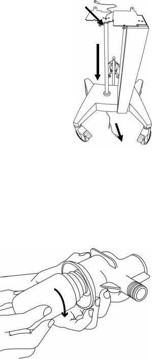
If you have purchased the optional external battery pack, the drop cable should be fed up the central pole of the base and out through the cord routing well shown in figure 2.2 prior to attaching the base to the ventilator body. Install your external batteries per the installation instructions enclosed with the cart accessories kit (P/N 11372). Reference Installation Instructions L2353 for detailed directions.
When the cord is in place, use the handles on each side of the ventilator body to maneuver and align it with the thumbscrews on the base (see figure 2.1). Tighten the thumbscrews.
Figure 2.2 External Battery Routing
Setting Up the Front of the Ventilator
Assembling the Exhalation Filter and Water Trap
To assemble and insert the exhalation filter and water trap do the following:
Screw the supplied water collection bottle into the threaded cuff of the water trap.
Figure 2.3 Attaching the Collection Bottle to the Water Trap
L2786
2-4 |
Chapter 2 Unpacking & Setup |
AVEA Ventilator Systems |
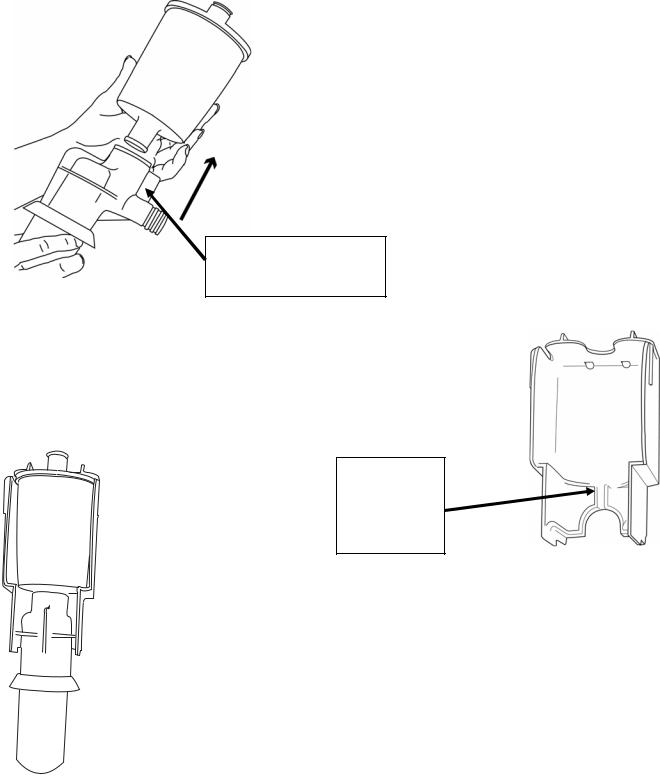
Push the exhalation filter into the water trap assembly top as shown.
Locating Ridge for assembly into cartridge
Figure 2.4 Attaching the Exhalation Filter.
Align the locating ridge on the water trap assembly with the slot in the exhalation filter cartridge (see fig 2.5).
Slot matches locating ridge of water trap assembly
Figure 2.5 Exhalation Filter Cartridge Showing Locating Slot
Slide the water trap/exhalation filter assembly into the cartridge (see fig 2.6)
Figure 2.6 Exhalation Filter/Water Trap Assembly in Cartridge
L2786

Operator’s Manual |
Chapter 2 Unpacking & Setup |
2-5 |
Rotate the metal locking lever on the lower right of the ventilator body forward to an open position.
Figure 2.7 Open locking lever
Insert the completed cartridge assembly into the ventilator body as shown. Make sure it is completely seated in the well.
Figure 2.8 Insert exhalation filter
Note
Placement of the exhalation filter/water trap assembly without the exhalation filter cartridge may cause misalignment of the filter seal resulting in patient breathing circuit leaks.
Close the locking lever.
Figure 2.9 Close locking lever in place
L2786

2-6 |
Chapter 2 Unpacking & Setup |
AVEA Ventilator Systems |
Attaching the Patient Circuit
Adult Circuit using an Active
Humidifier
Using an active humidifier, the adult patient circuit is set up as shown in figure 2.10. Attach your humidifier to the upright pole of the AVEA base. Adjust the height of the humidifier and the length of the humidifier tubing so that the tubing is relatively straight with no occlusions.
Adult Circuit without active humidifier
Inspiratory Limb
of Patient Circuit
Inspiratory limb of Patient Circuit
Figure 2.10 Adult Circuit with Active Humidifier
The setup for use with a passive humidifier or HME is per figure 2.11. The inspiratory limb of the patient circuit connects directly to the gas output of the ventilator. The passive humidification system should be placed in-line in the patient circuit per the manufacturer’s instructions.
Figure 2.11 Adult Patient Circuit without active humidifier.
L2786

Operator’s Manual |
Chapter 2 Unpacking & Setup |
2-7 |
Neonatal Patient Circuit
The Neonatal Patient Circuit is attached as shown in figure 2.12.
Front Panel Connections
Standard
Inspiratory Limb
of Patient Circuit
Figure 2.12 Neonatal Patient Circuit
Comprehensive
Figure 2.13 AVEA Front Panel Configurations Standard & Comprehensive
L2786

2-8 |
Chapter 2 Unpacking & Setup |
AVEA Ventilator Systems |
Attaching Flow Sensors
The AVEA can accept either a hot wire or a variable orifice proximal flow sensor. These are in addition to the instrument’s internal inspiratory flow sensor and heated expiratory flow sensor. Three proximal flow sensors are available for the AVEA.
The standard Hot Wire flow sensor is suitable for neonatal and pediatric applications where the peak inspiratory flow rate is less than 30 L/min. This flow sensor is not active in adult applications.
Hot Wire Flow Sensor
A Hot Wire flow sensor attaches to the receptacle circled in light blue directly below the variable orifice flow sensor connection on the front panel. The receptacle is marked with the icon shown here.
This is a locking connector. To attach, first pull back the locking collar, then push firmly onto the ventilator receptacle.
To disconnect, first retract the plastic collar then firmly pull the connector away from the ventilator. Do not pull up or down as this can damage the connector
Retractable plastic collar
Figure 2.14 Hot wire Flow Sensor Attachment
Note
Hot wire flow sensors will not function with Heliox gas mixtures. During Heliox delivery, a variable orifice flow sensor should be used for monitoring delivered volumes at the proximal airway.
Variable orifice flow sensors are also available on some AVEA models. The neonatal VarFlex flow sensor is compatible in neonatal and pediatric applications where the peak inspiratory flow rate is less than 30L/min and is not active in adult applications. For adult and large pediatric applications a Pediatric / Adult VarFlex flow sensor is available for use with patients whose flow requirements fall within the range of 1.2 – 180 L/min.
Detailed information on the specifications of each flow sensor can be found in Appendix E: Sensor Specifications and Circuit Resistance.
L2786

Operator’s Manual |
Chapter 2 Unpacking & Setup |
2-9 |
Variable Orifice Flow Sensor
Retractable
Plastic Collar
Variable Orifice sensors attach to the receptacle on the front panel of the ventilator circled in dark blue and marked with the icon shown here.
This is a locking connector. To attach, first pull back the plastic locking collar,
then push firmly onto the ventilator receptacle. Then push the locking collar forward to lock the flow sensor in place.
To disconnect, first retract the plastic collar then firmly pull the connector away from the ventilator. Do not pull up or down as this can damage the connector.
Figure 2.15 Variable Orifice
Flow Sensor Attachment
CAUTION
Fully retract the plastic locking collar before attaching these connectors. Failure to do this can cause damage to the connector.
Attaching a Nebulizer
You can use an in-line nebulizer with the AVEA ventilator (see Chapter 3, Ventilator Operation). The nebulizer is synchronized with inspiration, delivers gas at the set FiO2/FiHe and is active for 20 minutes. Attach the nebulizer tubing to the fitting at the bottom of the front panel as shown here. The fitting is marked with the icon shown here.
Figure 2.16 Attaching nebulizer tubing
Note
To use the internal nebulizer, the AVEA must be connected to a high-pressure air source. The nebulizer is not active while the AVEA is operating on its internal compressor. The ventilator incorporates an internal pneumatic compressor, which creates the drive pressure necessary to operate the nebulizer.
L2786

2-10 |
Chapter 2 Unpacking & Setup |
AVEA Ventilator Systems |
Note
The nebulizer requires an inspiratory flow rate of at least 15 liters per minute to activate and is flow compensated to maintain set tidal volumes.
CAUTION
When the internal nebulizer is used, the ventilator decreases the flow rate by 6 L/min to compensate for the nebulizer output. However, since flow from the internal nebulizer can vary, using the internal nebulizer may impact the tidal volumes delivered to the patient.
Note
Do not operate the nebulizer while using Heliox
Attaching a Proximal Pressure Sensor
A proximal pressure sensor to monitor proximal airway pressure can be attached to the Comprehensive model of AVEA. On the Comprehensive AVEA the connector is labeled as Aux as shown in figure 2.17.
When active, this feature will display & alarm to proximal airway pressures.
Figure 2.17 Proximal pressure sensor connection on the Comprehensive AVEA
Note
In applications which generate high resistances within the breathing system monitored, Proximal Airway Pressure may be higher than set Inspiratory Pressure.
L2786
Loading...