


Service Manual
AVEA Ventilator Systems
L1524 Rev. C
© 2006 VIASYS® Respiratory Care Inc.

Service Manual
ii |
L1524 |
AVEA Ventilator Systems
Revision History
Date |
Revision |
Pages |
Changes |
August 2002 |
Rev. A |
All |
Released Engineering Document |
|
|
|
Control ECO |
July 2003 |
Rev. B |
All |
Add Exception button and |
|
|
|
Exception screen to Error Log |
|
|
|
screen. Add list of error codes. |
|
|
|
Add OVP kits & instructions. |
|
|
|
Add Software upgrade |
|
|
|
instructions. Add heliox Smart |
|
|
|
connector instructions. Add |
|
|
|
Compressor upgrade |
|
|
|
instructions. Add cart instructions |
|
|
|
(both). Add external battery |
|
|
|
pack instructions. Add Insp & |
|
|
|
Exp transducer Cal instructions. |
|
|
|
Add ref to Communications |
|
|
|
Protocol. Add unpacking & |
|
|
|
setup instructions. |
|
|
|
Reorganize chapters, add |
|
|
|
chapter 3, add chapter 5 (OVP), |
|
|
|
add software upgrade info |
|
|
|
(chapter 6), add chapter 9, add |
|
|
|
chapter 10, add appendix D. |
L1524 |
iii |
|
|
|
Service Manual |
|
|
|
|
January 2006 |
Rev. C |
Throughout |
Updated the company name. |
|
|
vi |
Added external batteries to the |
|
|
|
Limitation of Liability. |
|
|
1-7 |
Added symbols for the battery |
|
|
|
and for HeOx. |
|
|
2-1 |
Updated the General |
|
|
|
Description. |
|
|
2-2 |
Changed the references of the |
|
|
|
Tracheal Catheter and the |
|
|
|
Esophageal Balloon. |
|
|
2-3 |
Changed “O2 bottle” to “O2 tank.” |
|
|
2-6 |
Changed the Monitor MCU |
|
|
|
description. |
|
|
2-9 |
Updated the description of the |
|
|
|
power supply system and the |
|
|
|
Transducer / Alarm PCB. |
|
|
2-12 |
Updated the description of the |
|
|
|
heated expiratory system. |
|
|
3-1 |
Updated the standard-stand |
|
|
|
carton contents table. |
|
|
3-8 |
Updated the procedure for |
|
|
|
setting up the Customer |
|
|
|
Transport Cart kit. |
|
|
3-11 – 3-12 |
Updated figures. |
|
|
3-14 |
Added part number references to |
|
|
|
“E Cylinder Bracket Assembly |
|
|
|
Instructions.” |
|
|
4-1 |
Added Pediatric Patient Circuit to |
|
|
|
the list of equipment. |
|
|
4-2 |
Removed the note regarding the |
|
|
|
UIM. |
|
|
4-3 |
Replaced the word “arm” with |
|
|
|
“neck.” Removed the note |
|
|
|
regarding the UIM. |
|
|
4-4 |
Added a note regarding the |
|
|
|
screws to the Metal Top Cover |
|
|
|
section. |
|
|
4-4 – 4-7 |
Updated the Gas Delivery |
|
|
|
Engine Removal procedure. |
|
|
4-11 – 4-12 |
Updated the fuse specifications. |
|
|
4-15 – 4-16 |
Updated the Compressor /Scroll |
|
|
|
Pump section. |
iv |
L1524 |
AVEA Ventilator Systems
|
|
4-16 |
Changed the part number of the |
|
|
|
Enhanced Patient Monitor board. |
|
|
4-18 – 4-19 |
Added the fan assembly and |
|
|
|
power supply part numbers. |
|
|
4-22 |
Added part numbers to step 1 of |
|
|
|
the removal procedure. |
|
|
4-23 |
Changed step 5 of the |
|
|
|
Installation procedure to include |
|
|
|
the part number. |
|
|
5-1 |
Added references to PSI to the |
|
|
|
Setup procedure. |
|
|
5-4 – 5-7 |
Updated the Manual Alarms |
|
|
|
Testing section. |
|
|
5-10 |
Added two steps to the Testing |
|
|
|
Guidelines section. |
|
|
5-11 |
Added step 22 to the Membrane |
|
|
|
Switch test. |
|
|
5-12 – 513 |
Op. Verification Checklist |
|
|
5-16 |
Updated the Checkout Sheet. |
|
|
A-58 |
Replaced figure A-1 |
|
|
A-59 – A-60 |
Updated the MIB Connection |
|
|
|
section. |
|
|
A-61 |
Added the Blender Bleed |
|
|
|
section. |
|
|
A-62 |
Added the Sound Levels section. |
|
|
A-63 – A-64 |
Updated the Water Trap section. |
|
|
A-66 |
Updated the Message Bar Text |
|
|
|
table. |
|
|
A-69 – A-74 |
Added the Monitor Ranges and |
|
|
|
Accuracies table. |
|
|
A-75 |
Added the Sensor Specifications |
|
|
|
and Circuit Resistance table. |
|
|
A-76 |
Added the Hot Wire Flow Sensor |
|
|
|
Specifications table. |
|
|
A-77 |
Added the Circuit Resistance |
|
|
|
section. |
L1524 |
v |
Service Manual
Notices
Copyright Notice
Copyright © 2006 VIASYS Respiratory Care Inc.
This work is protected under Title 17 of the U.S. Code and is the sole property of the Company. No part of this document may be copied or otherwise reproduced, or stored in any electronic information retrieval system, except as specifically permitted under U.S. Copyright law, without the prior written consent of the Company. For more information, contact:
USA |
|
European Authorized Representative |
||
VIASYS Respiratory Care Inc. |
VIASYS Healthcare GmbH |
|||
22745 Savi Ranch Parkway |
Leibnizstrasse 7 |
|
||
Yorba Linda, California 92887-4668 |
97204 Höchberg |
|
||
U.S.A. |
|
Germany |
|
|
Telephone: |
800 231-4645 |
|
|
|
|
(1) (714) 283-2228 |
Telephone: |
(49) (931) |
4972-0 |
Fax: |
(1) (714) 283-8471 |
Fax: |
(49) (931) |
4972-423 |
|
www.viasyshealthcare.com |
|
|
|
Trademark Notices
AVEA® is a registered trademark of VIASYS Respiratory Care Inc. in the U.S. and some other countries. All other brand names and product names mentioned in this manual are trademarks, registered trademarks, or trade names of their respective holders.
EMC Notice
This equipment generates, uses, and can radiate radio frequency energy. If not installed and used in accordance with the instructions in this manual, electromagnetic interference may result. The equipment has been tested and found to comply with the limits set forth in EN60601-1-2 for Medical Products. These limits provide reasonable protection against electromagnetic interference when operated in the intended use environments described in this manual.
The ventilator has been tested to conform to the following specifications:
MIL-STD-461D:1993, MIL-STD-462D:1993, EN55011:1991, IEC 1000-4-2:1994, IEC 1000-4-3:1994, IEC 1000-4-4:1994, IEC 1000-4-5:1994, QUASI-STATIC:1993
This ventilator is also designed and manufactured to comply with the safety requirements of IEC 601-1, IEC 601-2-12, CAN/CSA-C22.2 No. 601.1-M90, and UL 2601-1.
vi |
L1524 |

AVEA Ventilator Systems
MRI Notice
This equipment contains electromagnetic components whose operation can be affected by intense electromagnetic fields.
Do not operate the ventilator in an MRI environment or in the vicinity of high-frequency surgical diathermy equipment, defibrillators, or short-wave therapy equipment. Electromagnetic interference could disrupt the operation of the ventilator.
Intended Use Notice
The AVEA Ventilators are designed to provide ventilator support for the critical care management of infant, pediatric or adult patients with compromised lung function. They are intended to provide continuous respiratory support in an institutional health care environment. They should only be operated by properly trained clinical personnel, under the direction of a physician.
Regulatory Notice
Federal law restricts the sale of this device except by or on order of a physician.
IEC Classification
Type of Equipment: Medical Equipment, Class 1 type B
Adult/Pediatric/Infant Lung Ventilator
Declaration of Conformity Notice
This medical equipment complies with the Medical Device Directive, 93/42/EEC, and the following Technical Standards, to which Conformity is declared:
EN60601-1
EN60601-1-2 ISO 13485
EU Notified Body: |
|
BSI (Reg. No. 0086) |
|
Trade names: |
0086 |
AVEA Ventilator
If you have a question regarding the Declaration of Conformity for this product, please contact VIASYS Respiratory Care Inc. at the number given in Appendix A.
L1524 |
vii |
Service Manual
Warranty
THE AVEA® ventilator systems are warranted to be free from defects in material and workmanship and to meet the published specifications for TWO (2) years or 16,000 hours, whichever occurs first.
The liability of VIASYS Respiratory Care Inc., (referred to as the Company) under this warranty is limited to replacing, repairing or issuing credit, at the discretion of the Company, for parts that become defective or fail to meet published specifications during the warranty period; the Company will not be liable under this warranty unless (A) the Company is promptly notified in writing by Buyer upon discovery of defects or failure to meet published specifications; (B) the defective unit or part is returned to the Company, transportation charges prepaid by Buyer; (C) the defective unit or part is received by the Company for adjustment no later than four weeks following the last day of the warranty period; and
(D) the Company’s examination of such unit or part shall disclose, to its satisfaction, that such defects or failures have not been caused by misuse, neglect, improper installation, unauthorized repair, alteration or accident.
Any authorization of the Company for repair or alteration by the Buyer must be in writing to prevent voiding the warranty. In no event shall the Company be liable to the Buyer for loss of profits, loss of use, consequential damage or damages of any kind based upon a claim for breach of warranty, other than the purchase price of any defective product covered hereunder.
The Company warranties as herein and above set forth shall not be enlarged, diminished or affected by, and no obligation or liability shall arise or grow out of the rendering of technical advice or service by the Company or its agents in connection with the Buyer's order of the products furnished hereunder.
Limitation of Liabilities
This warranty does not cover normal maintenance such as cleaning, adjustment or lubrication and updating of equipment parts. This warranty shall be void and shall not apply if the equipment is used with accessories or parts not manufactured by the Company or authorized for use in writing by the Company or if the equipment is not maintained in accordance with the prescribed schedule of maintenance.
The warranty stated above shall extend for a period of TWO (2) years from date of shipment or 16,000 hours of use, whichever occurs first, with the following exceptions:
1.Components for monitoring of physical variables such as temperature, pressure, or flow are warranted for ninety (90) days from date of receipt.
2.Elastomeric components and other parts or components subject to deterioration, over which the Company has no control, are warranted for sixty (60) days from date of receipt.
3.Internal batteries are warranted for ninety (90) days from the date of receipt.
4.External batteries are warranted for one (1) year from the date of receipt.
The foregoing is in lieu of any warranty, expressed or implied, including, without limitation, any warranty of merchantability, except as to title, and can be amended only in writing by a duly authorized representative of the Company.
viii |
L1524 |
AVEA Ventilator Systems
Contents
Revision History............................................................................................................. |
iii |
|
Notices ............................................................................................................................ |
|
vi |
Warranty........................................................................................................................ |
|
viii |
Chapter 1 |
Introduction ............................................................................................. |
1-1 |
Safety Information...................................................................................................................... |
1-1 |
|
Equipment Symbols................................................................................................................... |
1-4 |
|
Chapter 2 Theory of Operation ................................................................................ |
2-1 |
|
General Description ................................................................................................................... |
2-1 |
|
High Level Design ...................................................................................................................... |
2-3 |
|
Detail Design .............................................................................................................................. |
2-5 |
|
Chapter 3 |
Installation Instructions.......................................................................... |
3-1 |
Stand Assembly ......................................................................................................................... |
3-1 |
|
Comprehensive Assembly Instructions ................................................................................... |
3-4 |
|
Customer Transport Cart Kit P/N 11372 ................................................................................... |
3-8 |
|
“E” Cylinder Bracket Assembly Instructions......................................................................... |
3-14 |
|
Assembly Instructions for Comprehensive Cart Tank Rack Bracket ................................. |
3-18 |
|
AVEA Unpacking Instructions................................................................................................. |
3-19 |
|
SETTING UP THE REAR OF THE VENTILATOR..................................................................... |
3-22 |
|
Medical Gas Connector Kit Installation Instructions ............................................................ |
3-22 |
|
Air and Heliox Tethered “Smart” Connector Installation Instructions ................................ |
3-25 |
|
Heliox “Smart” Connector Installation Instructions (DISS P/N 51000-40918) ..................... |
3-27 |
|
Chapter 4 Assembly and Disassembly................................................................... |
4-1 |
|
General Instructions and Warnings.......................................................................................... |
4-1 |
|
Recommended Tools & Equipment .......................................................................................... |
4-1 |
|
Gas Delivery Engine P/N 16222A .............................................................................................. |
4-4 |
|
Ventilator wheeled base .......................................................................................................... |
4-10 |
|
Internal Batteries P/N 68339A.................................................................................................. |
4-10 |
|
Compressor/Scroll Pump P/N 51000-09750A......................................................................... |
4-15 |
|
Enhanced Patient Monitor (EPM) Board P/N 51000-40848A ................................................. |
4-16 |
|
L1524 |
ix |
Service Manual
Fan Assembly P/N 51000-40861 ............................................................................................. |
4-18 |
Power Supply P/N 16388 ......................................................................................................... |
4-19 |
Exhalation Valve P/N 16319 and Exhalation Flow Sensor Assembly P/N 51000-40023 ...... |
4-22 |
Exhalation housing P/N 20030................................................................................................. |
4-22 |
Heater Assembly P/N 51000-40824.......................................................................................... |
4-24 |
Microswitch, Top Cover P/N 68294......................................................................................... |
4-24 |
EMI Shield.................................................................................................................................. |
4-25 |
Front Interface Panel P/N 51000-40635 ................................................................................... |
4-25 |
Transition board with harness P/N 16216............................................................................... |
4-27 |
Alarm Speaker P/N 51000-40818............................................................................................. |
4-28 |
Nebulizer Assembly P/N 51000-40026.................................................................................... |
4-29 |
Accumulator P/N 51000-40748................................................................................................. |
4-31 |
Secondary Alarm Installation (KitP/N 16316).......................................................................... |
4-32 |
General Instructions and Warnings ........................................................................................ |
4-32 |
Recommended Tools & Equipment......................................................................................... |
4-32 |
Functional testing of the Secondary Alarm Assembly. ......................................................... |
4-34 |
Chapter 5 Operational Verification Procedure (OVP) ........................................... |
5-1 |
Set up.......................................................................................................................................... |
5-1 |
User Verification Tests (UVT) ................................................................................................... |
5-1 |
Return Flow Correction to BTPS upon completion of testing. ..................................................... |
5-10 |
User Interface Module (UIM) Verification ................................................................................ |
5-10 |
AVEA Assembly and Operational Verification Test Checklist .............................................. |
5-12 |
Field replacement and test of the AVEA Compressor Assembly ......................................... |
5-12 |
Checkout Sheet – AVEA Compressor Replacement.............................................................. |
5-16 |
Power Indicators and Charging Verification........................................................................... |
5-17 |
Battery Run Procedure............................................................................................................. |
5-17 |
Air/Oxygen Inlet Pressure Verification.................................................................................... |
5-18 |
Breath Rate Verification. .......................................................................................................... |
5-19 |
Blending Accuracy Verification............................................................................................... |
5-19 |
PEEP Verification...................................................................................................................... |
5-19 |
AVEA Assembly and Operational Verification Test Checklist .............................................. |
5-20 |
x |
L1524 |
AVEA Ventilator Systems
Chapter 6 AVEA Software Upgrade......................................................................... |
6-1 |
|
Requirements: ............................................................................................................................ |
6-1 |
|
Procedure: .................................................................................................................................. |
6-2 |
|
Software Install Verification AVEA Ventilators ...................................................................... |
6-11 |
|
Installation Verification............................................................................................................ |
6-11 |
|
Confirmation checks................................................................................................................ |
6-11 |
|
Verification and Calibration..................................................................................................... |
6-12 |
|
Test and Access of the Security System ............................................................................... |
6-12 |
|
Chapter 7 |
Calibration................................................................................................ |
7-1 |
Screen Calibration Procedure................................................................................................... |
7-1 |
|
Transducer Calibration .............................................................................................................. |
7-4 |
|
Calibration setup ........................................................................................................................ |
7-5 |
|
Flow and Exhalation valve Characterization/Hysteresis Test .............................................. |
7-18 |
|
Exhalation Valve Characterization Test ................................................................................. |
7-19 |
|
Hysteresis Test......................................................................................................................... |
7-20 |
|
Exhalation Valve Leak Test ..................................................................................................... |
7-21 |
|
Chapter 8 |
Preventive Maintenance ......................................................................... |
8-1 |
Replacing the O2 and Air/Heliox filters. ................................................................................... |
8-2 |
|
Replacing the Compressor Inlet & Outlet filters...................................................................... |
8-4 |
|
Replacing the Exhalation Diaphragm P/N 16240 ..................................................................... |
8-5 |
|
Chapter 9 |
Troubleshooting ...................................................................................... |
9-1 |
Chapter 10 |
Parts List............................................................................................. |
10-1 |
L1524 |
xi |
|
Service Manual |
Appendix A................................................................................................................... |
A-1 |
Contact & Ordering Information ............................................................................................... |
A-1 |
Diagrams and Schematics ........................................................................................................ |
A-2 |
Specifications .......................................................................................................................... |
A-55 |
AVEA Message Bar Text ......................................................................................................... |
A-66 |
Adjusting Barometric Pressure for Altitude .......................................................................... |
A-68 |
Monitor Ranges and Accuracies ............................................................................................ |
A-69 |
Sensor Specifications & Circuit Resistance.......................................................................... |
A-75 |
Hot Wire Flow Sensor Specifications..................................................................................... |
A-76 |
Circuit Resistance (per EN794 –1).......................................................................................... |
A-77 |
Advanced Pulmonary Mechanics Monitored Parameters .................................................... |
A-78 |
Glossary ................................................................................................................................... |
A-85 |
Index ................................................................................................................................. |
1 |
xii |
L1524 |
Service Manual AVEA Ventilator Systems
Chapter 1 Introduction
Safety Information
Please review the following safety information prior to operating the ventilator. Attempting to operate the ventilator without fully understanding its features and functions may result in unsafe operating conditions.
Warnings and Cautions which are general to the use of the ventilator under all circumstances are included in this section. Some Warnings and Cautions are also inserted within the manual where they are most meaningful.
Notes are also located throughout the manual to provide additional information related to specific features.
If you have a question regarding the installation, set up, operation, or maintenance of the ventilator, contact VASYS Respiratory Care customer care as shown in Appendix A, Contact & Ordering Information.
Terms
WARNINGS |
identify conditions or practices that could result in serious adverse reactions or |
|
potential safety hazards. |
CAUTIONS |
identify conditions or practices that could result in damage to the ventilator or other |
|
equipment. |
NOTES |
identify supplemental information to help you better understand how the ventilator |
|
works. |
Warnings |
|
Warnings and Cautions appear throughout this manual where they are relevant. The Warnings and Cautions listed here apply generally any time you work on the ventilator.
•Alarm loudness must be set above ambient sound in order to be heard.
•Due to possible explosion hazard, the ventilator should not be used in the presence of flammable anesthetics.
•An audible alarm indicates an anomalous condition and should never go unheeded.
•Anti-static or electrically conductive hoses or tubing should not be used within the patient circuit.
•If a mechanical or electrical problem is recognized while running the Operational Verification Tests, or while operating the ventilator, the ventilator must be removed from use until the problem has been identified and resolved.
•The functioning of this equipment may be adversely affected by the operation of other equipment nearby, such as high frequency surgical (diathermy) equipment, defibrillators, short-wave therapy equipment, “walkie-talkies,” or cellular phones.
•Water in the air supply can cause malfunction of this equipment.
L1524 |
1-1 |
Service Manual
•Do not block or restrict the Oxygen bleed port located on the instrument back panel. Equipment malfunction may result.
•Electric shock hazard – Ensure the ventilator is disconnected from the AC power supply before performing and repairs or maintenance. When you remove any of the ventilator cover panels, immediately disconnect the internal battery “quick release” connector before working on the ventilator. If the ventilator has an external battery installed, ensure that the external battery is unplugged from the rear panel before proceeding
•A protective ground connection by way of the grounding conductor in the power cord is essential for safe operation. Upon loss of protective ground, all conductive parts including knobs and controls that may appear to be insulated, can render an electric shock. To avoid electrical shock, plug the power cord into a properly wired receptacle, use only the power cord supplied with the ventilator, and make sure the power cord is in good condition.
The following warnings must be read and understood before performing the procedures described in this manual.
•Under no circumstances should this medical device be operated in the presence of flammable anesthetics or other volatile materials due to a possible explosion hazard.
•Liquid spilled or dripped into the unit may cause damage to the unit or result in an electrical shock hazard.
•Oxygen vigorously accelerates combustion. To avoid violent ignition, do not use any gauges, valves, or other equipment that has been exposed to oil or grease contamination.
•Do not use this device if any alarm/alert function is inoperative. To do so could result in a malfunction without warning, possibly resulting in personal injury, including death or property damage.
•All tubing and fittings used to connect high pressure gas from the source to the test equipment and from the test equipment to the device being tested must be capable of withstanding a minimum supply pressure of 100 psi (7.03 kg/cm2). The use of tubing and fittings not capable of withstanding this pressure could cause the tubing to rupture, resulting in personal injury or property damage.
•When verifying the operation of this medical device, do not breathe directly from the machine. Always use a fresh bacterial filter and test circuit. Failure to do so may constitute a hazard to the health of the service person.
•If any of the procedures outlined in this document cannot be verified, do not use this device and refer it to VIASYS Respiratory Care or a VIASYS Respiratory Care authorized service facility or a VIASYS Respiratory Care trained hospital service technician.
1-2 |
L1524 |
AVEA Ventilator Systems
Cautions
The following cautions apply any time you work with the ventilator.
•Ensure that the voltage selection and installed fuses are set to match the voltage of the wall outlet, or damage may result.
•A battery that is fully drained (i.e. void of any charge) may cause damage to the ventilator and should be replaced.
•All accessory equipment that is connected to the ventilator must comply with CSA/IEC601/UL2601.
•To avoid damage to the equipment, clean the air filter regularly.
The following cautions apply when cleaning the ventilator or when sterilizing ventilator accessories.
•Do not sterilize the ventilator. The internal components are not compatible with sterilization techniques.
•Do not gas sterilize or steam autoclave tubing adapters or connectors in place. The tubing will, over time, cause poor connection and possible leaks.
•DO NOT submerge the ventilator or pour cleaning liquids over or into the ventilator.
•Do not use MEK, Trichloroethylene or similar solutions as damage to surface may result. Do not allow any liquid to spill or drip into the ventilator.
•Circuit boards are subject to damage by static electricity. Do not touch components, circuit, or connector fingers with hands. Handle only by edges.
L1524 |
1-3 |
Service Manual
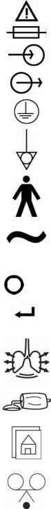
Equipment Symbols
The following symbols may be referenced on the ventilator or in accompanying documentation
|
Symbol |
Source/Compliance |
Meaning |
||
|
|
|
Symbol #03-02 IEC 60878 |
Indicates ATTENTION, consult ACCOMPANYING DOCUMENTS |
|
|
|
|
|
|
|
|
|
|
Symbol #5016 IEC 60417 |
This symbol indicates a FUSE. |
|
|
|
|
Symbol #5034 IEC 60417 |
This symbol indicates INPUT. |
|
|
|
|
Symbol #01-36 IEC 60878 |
||
|
|
|
|
||
|
|
|
Symbol #5035 IEC 60417 |
This symbol indicates OUTPUT |
|
|
|
|
Symbol #01-37 IEC 60878 |
||
|
|
|
|
||
|
|
|
Symbol #5019 IEC 60417 |
This symbol indicates protective EARTH (ground). |
|
|
|
|
Symbol #01-20 IEC 60878 |
||
|
|
|
|
||
|
|
|
Symbol #5021 IEC 60417 |
This symbol indicates the EQUIPOTENTIAL connection used to |
|
|
|
|
connect various parts of the equipment or of a system to the |
||
|
|
|
Symbol # 01-24 IEC 60878 |
same potential, not necessarily being the earth (ground) potential |
|
|
|
|
|
(e.g., for local bonding). |
|
|
|
|
Symbol # 5333 IEC 60417 |
This symbol indicates TYPE B equipment, which indicates |
|
|
|
|
|||
|
|
|
equipment that provides a particular degree of protection against |
||
|
|
|
Symbol #02-03 IEC 60878 |
electric shock, particularly with regards to allowable leakage |
|
|
|
|
|
current and reliability of the protective earth connection. |
|
|
|
|
|
||
|
|
|
Symbol #5032 IEC 60417 |
This symbol is located on the rating plate. It indicates the |
|
|
|
|
Symbol #01-14 IEC 30878 |
equipment is suitable for alternating current. |
|
|
|
|
Symbol #5007 IEC 60417 |
Indicates ON (Power) |
|
|
|
|
|||
|
|
|
Symbol #01-01 IEC 60878 |
||
|
|
|
|
|
|
|
|
|
Symbol #5008 IEC 60417 |
Indicates OFF (Power) |
|
|
|
|
Symbol #01-02 IEC 60878 |
||
|
|
|
|
||
|
|
|
Symbol #0651 ISO 7000 |
Horizontal return with line feed. Indicates ACCEPT entered |
|
ACCEPT |
values for a specific field. |
||||
|
|||||
|
|
||||
|
|
|
VIASYS Respiratory Care Symbol |
Indicates PATIENT EFFORT |
|
|
|
|
|
|
|
|
|
|
VIASYS Respiratory Care symbol |
Indicates MANUAL BREATH |
|
|
|
|
|
|
|
|
|
|
VIASYS Respiratory Care Symbol |
MAIN SCREEN |
|
|
|
|
|
|
|
|
|
|
Symbol #417 IEC 5102 |
EVENT READY |
|
|
|
|
|
|
|
1-4 |
L1524 |

AVEA Ventilator Systems
|
VIASYS Respiratory Care Symbol |
MODE |
|
|
|
|
VIASYS Respiratory Care Symbol |
ADVANCED SETTINGS |
|
|
|
|
VIASYS Respiratory Care Symbol |
SET-UP for patient Data |
|
|
|
|
VIASYS Respiratory Care Symbol |
SiPAP Duration |
|
|
|
|
MDD Directive 93/42/EEC |
CE Mark |
|
|
|
|
Symbol #5307 IEC 60417 |
ALARM RESET |
|
|
|
|
Symbol #5319 IEC 60417 |
ALARM SILENCE |
|
|
|
|
VIASYS Respiratory Care symbol |
ADULT patient |
|
|
|
|
VIASYS Respiratory Care symbol |
PEDIATRIC patient |
|
|
|
|
VIASYS Respiratory Care symbol |
NEONATAL (Infant) patient |
|
|
|
|
Graphical Symbol in general use |
CANCEL, do not accept entered values. |
|
internationally for “DO NOT” |
|
CANCEL |
|
|
|
|
|
|
VIASYS Respiratory Care symbol |
Select DISPLAYED SCREEN function. |
|
|
|
|
Symbol 5467 IEC 60417 |
FREEZE the current display. |
|
|
|
|
VIASYS Respiratory Care symbol |
Enable the ALARM LIMITS screen |
|
|
|
|
VIASYS Respiratory Care symbol |
This symbol indicates a CONTROL LOCK. |
|
|
|
L1524 |
1-5 |
Service Manual
|
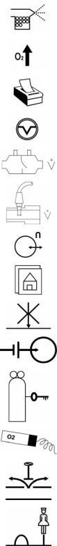
VIASYS Respiratory Care symbol |
NEBULIZER port |
|
|
|
|
VIASYS Respiratory Care symbol |
Increase OXYGEN |
|
|
|
|
VIASYS Respiratory Care symbol |
PRINT SCREEN |
|
|
|
|
VIASYS Respiratory Care symbol |
SUCTION port |
|
|
|
|
VIASYS Respiratory Care symbol |
VARIABLE ORIFICE FLOW SENSOR connection |
|
|
|
|
VIASYS Respiratory Care symbol |
HOT WIRE FLOW SENSOR connection |
|
|
|
|
VIASYS Respiratory Care symbol |
ANALOG IN/OUT connection |
|
|
|
|
VIASYS Respiratory Care symbol |
Display the MAIN SCREEN |
|
|
|
|
VIASYS Respiratory Care symbol |
DO NOT BLOCK PORT |
|
|
|
|
VIASYS Respiratory Care symbol |
EXTERNAL BATTERY connection |
|
|
|
|
VIASYS Respiratory Care symbol |
Indicates GAS ID port |
|
|
|
|
VIASYS Respiratory Care symbol |
OXYGEN SENSOR connection |
|
|
|
|
VIASYS Respiratory Care symbol |
OVERPRESSURE relief |
|
|
|
|
VIASYS Respiratory Care symbol |
REMOTE NURSE CALL connection |
|
|
|
1-6 |
L1524 |
AVEA Ventilator Systems
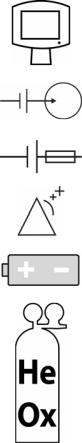
|
VIASYS Respiratory Care symbol |
UNIVERSAL INTERFACE MONITOR connection |
|
|
|
|
VIASYS Respiratory Care Symbol |
This symbol indicates an EXTERNAL BATTERY INPUT |
|
|
|
|
VIASYS Respiratory Care Symbol |
This symbol indicates an INTERNAL BATTERY FUSE |
|
|
|
|
VIASYS Respiratory Care Symbol |
This symbol indicates ALARM LOUDNESS |
|
|
|
|
VIASYS Respiratory Care Symbol |
Operating on Battery Indicator |
|
|
|
|
VIASYS Respiratory Care Symbol |
Operating on Heliox |
|
|
|
L1524 |
1-7 |
Service Manual
1-8 |
L1524 |
Service Manual |
AVEA Ventilator Systems |
Chapter 2 Theory of Operation
General Description
AVEA is a software driven, servo-controlled ventilator designed to meet the requirements of neonate to adult patients. The design intent of the device is to provide a high performance software-driven gas delivery engine, which is capable of providing a full range of volume and pressure ventilation including dual limb NIPPV. This affords the flexibility of developing new modes of ventilation with no impact to the basic gas delivery engine. In addition, the device will contain a graphical user interface (GUI) that utilizes a 12.1-inch SVGA color LCD screen with integral touch screen. The GUI will be used to change settings and operating parameters as well as providing real time waveforms, digital monitors, and alarms. The device also contains an internal battery that serves as a backup in case of loss of hospital AC power. The Custom Cart may be equipped with tank holder, external batteries and battery tray for use of the AVEA during inter-facility transport.
There are three models of AVEA; comprehensive, plus and standard. These are shown in table 2.1 based on the same basic platform. Additional models may be developed in the future by adding or removing software and/or hardware features to the existing platform.
The AVEA is a fourth generation, servo-controlled, software-driven ventilator. It has a dynamic range of breathing gas delivery that provides for neonatal through adult patients. Its revolutionary user interface module (UIM) provides maximum flexibility with simple operator interaction. It has a flat panel color LCD with real time graphic displays and digital monitoring capabilities, a touch screen for easy interaction, membrane keys and a dial for changing settings and operating parameters. A precision gas delivery engine with servo controlled active inhalation and exhalation improves performance over previous generations.
The AVEA has been designed to function using most commonly available accessories. It is easy to clean and its design does not allow liquids to pool on the casing, reducing the likelihood of fluid leakage into the body of the ventilator.
L1524 |
2-1 |
Service Manual
There are three models of AVEA to choose from: The Comprehensive, Plus, and the Standard. The following matrix details the standard and optional functions available with each model.
Functions & Accessories |
Standard |
Plus |
Comprehensive |
Modes |
All |
All |
All |
Proximal Hot Wire Flow Sensing |
|
|
|
Synchronized Nebulizer |
|
|
|
24 Hour Trending |
|
|
|
Internal Battery |
|
|
|
Full Color Graphics Display |
|
|
|
Loops and Waveforms |
|
|
|
Standard Cart |
|
|
|
Proximal Variable Orifice flow sensing |
|
|
|
Proximal Airway Pressure Monitoring |
|
|
|
Tracheal Pressure Monitoring |
|
|
|
Esophageal Pressure Balloon |
|
|
|
Internal Compressor |
|
|
|
Heliox Delivery |
|
|
|
|
|
|
|
Optional Functions & Accessories |
|
|
|
Custom Cart |
Option |
Option |
Included |
External Battery (on custom cart only) |
Option |
Option |
Option |
Gas Tank Holder (on either cart) |
Option |
Option |
Option |
Internal Compressor |
Option |
Option |
Included |
Heliox Delivery |
Option |
Option |
Included |
2-2 |
L1524 |
AVEA Ventilator Systems
High Level Design
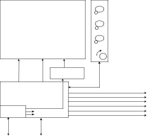
AVEA has been designed with three basic modules, the user interface module (UIM), the pneumatics module (PM), and the stand (see Figure 1). The UIM contains a graphical user interface (GUI) which utilizes a 12.1-inch SVGA color LCD screen with integral touch screen. The UIM also contains a control PCB that has two microprocessors, control and monitor. The monitor processor manages the GUI, while the control processor has the real time control system that controls all of the mechanical valves in the PM. The UIM communicates with the PM via a high-speed serial channel (HSSC). The HSSC also provides power to the UIM.
The pneumatics module (PM) contains all of the mechanical valves, sensors, analog electronics, power supply including the internal batteries, and the optional internal compressor. The pneumatics module takes high-pressure air or 80/20 heliox and oxygen from an external wall source or other high-pressure source. It filters the gas and blends them through a stepper motor controlled blender according to the front panel settings. It then delivers the appropriate pressure or volume via a high-speed proportional solenoid with flow sensor feedback. The high-speed control system occurs every 2 msec and is computed in the control microprocessor in the UIM. The delivered gas flows to the patient through a safety valve that has a mechanical over pressure relief valve as well as a sub-ambient valve. The gas is forced into the patient by closing the servo-controlled voice coil exhalation valve, which is also controlled by the control microprocessor in the UIM. The patient is allowed to exhale by the voice coil exhalation valve, which also maintains baseline pressure or PEEP. The exhaled gas exits the patient through the expiratory limb of the patient circuit to an integral heated expiratory filter to an external flow sensor and out the exhalation valve to ambient air.
The pneumatics module has several additional capabilities. First it uses either air or 80/20 heliox for an input gas, and corrects all blending, volume delivery, volume monitoring and alarming, and FiO2 monitoring and alarming based on the correct gas density. The system knows what the gas is, by a patent pending gas ID that identifies the appropriate inlet DISS fitting with the gas that is being delivered, which creates an inherently safer system for delivering heliox. The second capability is the optional back up compressor that is battery backed up for a minimum of 30 minutes by a fully charged internal battery, which allows for uninterrupted ventilation during a loss of AC power. The third feature is the ability to monitor volume either at the expiratory limb of the machine or at the patient wye. This allows for more accurate patient monitoring especially in infants while allowing the convenience of an expiratory limb flow sensor protected by a heated filter. Finally, the fourth feature is the ability to measure tracheal and esophageal pressures, which is currently commercially available only on other VIASYS (Bear/Bird) ventilators.
The stand is used to support the ventilator at an ergonomically correct height. It may contain an optional external battery for extended use with AC power (custom stand only). It also has an optional O2 tank bracket so that the unit can be used without wall oxygen during inter-hospital transport. The stand does not contain active electronic or mechanical components other than the optional external batteries, which are charged when connected to A/C Power.
L1524 |
2-3 |
Service Manual
|
|
|
Printer |
|
USER |
|
RS232 x 2 |
|
INTERFACE |
||
|
MODULE |
|
|
User Input |
(UIM) |
|
MIB |
|
|
||
|
|
|
VGA |
|
|
High |
|
|
Power |
Speed |
|
|
Serial |
|
|
|
|
|
|
|
|
Channel |
|
|
|
(HSSC) |
|
Ambient Air |
|
Enhanced Pt. |
Pes |
|
|
Paux |
|
|
|
Monitors |
|
|
|
Faw |
|
Gas ID |
|
(Optional) |
|
|
|
||
|
|
|
|
Air/Heliox |
|
|
Nebulizer |
|
|
|
Drive gas |
O2 Supply |
|
|
|
AC Power |
|
|
|
24 VDC |
COMPRESSOR |
|
Humidfier Delivered Gas |
|
|
(Optional) |
|
|
(Optional) |
|
|
|
|
|
|
Nurse Call |
|
Patient |
|
|
|
Analog I/O, |
|
Exhaled Gas |
ILV |
|
from patient |
O2 |
PNEUMATICS MODULE |
Exhaust, |
sensor |
Exhaled Flow |
|
|
EXTERNAL BATTERY |
|
|
(Optional) |
|
CART
Figure 2-3 High End Device Modular Diagram
2-4 |
L1524 |
AVEA Ventilator Systems
Detail Design
User Interface Module (UIM)
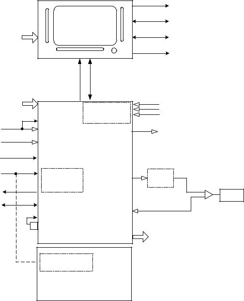
The UIM consists of a 12.1-inch, 800x600 active matrix LCD with an analog resistive touch screen overlay, a back light inverter, a set of membrane key panels, an optical encoder, and a Control PCB. Software and the touch screen provide a set of context sensitive soft keys. The membrane panel provides a set of hard (permanent) keys for dedicated functions. Selecting the function with a soft key and adjusting the setting using the optical encoder changes a parameter. The parameter is accepted or canceled by pressing the appropriate membrane key.
(3 & 4)
LCD & TOUCHSCREEN (1 & 2)
|
|
(5) |
MEMBRANE PANEL WITH |
|
|
|
EMBEDDED LED'S |
|
|
BACK LIGHT AC VOLTAGE |
|
DIGITAL |
TOUCH |
BACK LIGHT INVERTER |
|
SCREEN |
|
||
|
|
||
|
|
(6) |
|
CONTROL PCB |
|
DIGITAL |
|
|
|
|
|
(7) |
|
|
|
|
|
UNIVERSAL SERIAL BUS (FUTURE) |
|
|
|
|
PRINTER |
|
|
|
RS232 |
|
|
|
RS232 |
DC-DC |
5V |
|
RS232 (MIB) |
5V, PRN PORT |
|
||
CONVERTERS |
|
(CRT) |
|
3.3V, DIG LOGIC |
|
||
|
|
||
|
|
|
|
24VDC |
|
HIGH SPEED |
|
|
|
SERIAL |
|
Figure 2-4 User Interface Design Module Block Diagram
L1524 |
2-5 |
Service Manual
The UIM performs all ventilator control functions, gas calculations, monitoring and user interface functions. The UIM uses a Graphical User Interface (GUI) via the active matrix SVGA LCD and resistive touch screen to provide system and patient information to the user and to allow the user to modify ventilator settings. The Control PCB (with two micro-controllers, RAM, ROM and support electronics) provides all ventilator functions. The Control micro-controller (MCU) performs all gas calculations; controls all valves, solenoids, and electronics required to deliver blended gas to the patient. The Monitor MCU handles all user interface requirements, including updating the active matrix liquid crystal display (LCD), monitoring the membrane keypad, analog resistive touch screen, and optical encoder for activity. The Monitor MCU also performs all the input/output functions of the UIM, including RS-232, printer, video output, and communication to patient monitors. Communication between the Control and Monitor MCU’s is accomplished via an 8 bit dual port SRAM. In addition, both MPU's monitor each other and both are independently capable of activating the fail safe system.
The UIM is self-contained and is tethered to the pneumatics module with a high-speed data and power cable. All valves are contained in the pneumatics module; the control MCU controls all ventilator functions via the high-speed serial channel (HSSC). The Monitor MCU provides additional input/output functions contained in the ventilator. These functions include analog outputs, independent lung ventilation, and nurse call and are updated by the Monitor MCU via the HSSC.
Liquid Crystal Display
The liquid crystal display (LCD) provides graphical and digital feedback to the clinician. The panel is a 12.1” SVGA, 800x600 pixel, active matrix LCD. The LCD is used to implement the graphical user interface (GUI). It provides all of the adjustable controls and alarms, as well as displays waveforms, loops, digital monitors and alarm status in real time.
Touch Screen
The touch screen in conjunction with the LCD provides a set of software configurable soft keys. The software allows the keys to be context sensitive. The touch screen is a 12.1” analog resistive overlay on a piece of glass, which is placed over the LCD. It has a resolution of 1024x1024. Physically the touch screen, consists of two opposing transparent resistive layers separated by insulating spacers. Actuation brings the two opposing layers into electrical contact. The Y coordinate is determined by applying a voltage from top to bottom on the top resistive layer. This creates a voltage gradient across this layer. The point of contact forms a voltage divider, which is read by the analog-to-digital converter. The X coordinate is determined by applying a voltage from left to right on the bottom resistive layer. Again this creates a voltage gradient and the point of contact forms a divider, which is read with an analog-to- digital converter.
Membrane Panel
The membrane panel provides a set of permanent dedicated keys, which allow the clinician to change certain ventilator functions. The membrane panel will provide visual status to the clinician via embedded light emitting diodes (LEDs). The membrane panel consists of membrane switches, which are read by the monitor CPU. The switches form a matrix of rows and columns. A key closure causes an interrupt to the monitor CPU, which responds by scanning the key matrix to determine which key has been pressed.
Light Emitting Diodes (LEDs)
Some of the membrane keys require LED’s to indicate when the key is active. The LED’s are embedded into the membrane panels.
2-6 |
L1524 |
AVEA Ventilator Systems
Optical Encoder
The optical encoder allows the clinician to change settings. The setting to be changed is selected by pressing a soft key on the LCD and then turning the optical encoder to change the value. When the encoder is rotated two pulse streams are generated, phase A and B. When the encoder is turned clockwise, phase A leads B by 90 degrees. When the direction is counter clockwise, phase B leads A by 90 degrees. The electronics uses the phase information to drive an up-down counter, which is read by the monitor CPU. The optical encoder is not interrupt-driven and therefore must be polled by the monitor CPU.
Back Light Inverter
The back light inverter converts 5 VDC into the high frequency AC voltage necessary to power the LCD back light, which is used to illuminate the LCD.
Control PCB
The control PCB consists of two micro-controllers, the control CPU and the monitor CPU, both of which are 100 MHz ELAN 410’s. The control and associated circuitry (RAM, ROM, etc) micro controllers perform all ventilator control functions including the 2 msec closed loop flow control servo and the 2 msec closed loop exhalation valve control servo. The monitor micro-controller manages the GUI and performs all user input and output including the RS-232 ports, printer port, video out, and MIB port. The two processors communicate with each other via a dual port RAM. The control processor communicates with the pneumatics module via a high-speed serial channel (HSSC - 4 Mbits/sec).
Each processor has 8 Mbytes of DRAM, and one Mbyte of flash memory for program storage. In addition, the monitor circuitry also has a second one Mbyte of flash memory for saving control settings and trended data for clinical parameters. The control PCB also contains a DC-to-DC converter to regulate the incoming 24 VDC to the voltages used by the UIM. Finally, the control PCB also contains all of the circuitry necessary to scan the membrane panels, touch screen, and optical encoder, as well as the video controller necessary to drive the SVGA LCD screen.
L1524 |
2-7 |
Service Manual
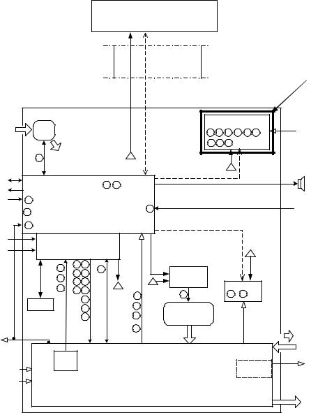
Pneumatics Module
The pneumatics module (PM) consists of a power supply system including internal NiMH batteries, a transducer/ communication/alarm PCB (TCA PCB), the pneumatics, a heated expiratory system, a fan, an optional internal compressor, a built-in nebulizer system, and an audible alarm. The PM communicates with the UIM (User Interface Module) via the HSSC described above.
User Interface Module
(UIM)
SHIELDED |
High |
|
Speed |
|
|
CABLE |
|
|
Serial |
|
|
|
Future software option. |
|
|
Channel |
|
|
|
|
|
|
|
Enhanced Pt.Monitoring (EPM) |
|
|||||
Ambient |
|
|
|
|
|
|
|
|
PCB (Optional) |
|
Faw, Ptr, Pes, |
||
|
Fan |
|
|
|
|
|
|
|
|
|
|
||
Air |
|
|
|
|
|
14 |
15 |
16 |
17 |
31 |
34 |
||
|
|
|
DC |
|
Paw |
||||||||
|
|
|
|
|
|||||||||
|
|
|
|
|
|
|
|
|
|
|
|
||
|
|
|
|
|
Power |
|
35 |
36 |
39 |
|
|
|
|
|
|
29 |
|
|
1 |
|
|
|
|
|
|
|
|
|
|
|
|
|
|
|
|
|
|
|
|
|
|
|
|
|
|
|
|
|
|
|
1 |
|
|
|
|
Analog I/O, |
|
|
|
|
|
|
HSSC |
|
|
|
|
|
|
ILV |
|
|
|
9 |
21 |
|
|
|
|
|
|
|
Alarm |
Nurse Call |
|
|
|
|
|
|
|
|
|
|
|||
|
|
|
|
|
|
|
|
|
|
|
|
|
|
Gas ID |
10 |
Transducer/Comm./Alarm (TCA) |
|
|
|
|
|
|
|
|
|||
|
18 |
|
|
PCB |
|
12 |
|
|
|
|
|
|
HW Flow |
|
|
|
|
|
|
|
|
|
|
|
|
|
|
|
7 |
|
|
|
|
|
|
|
|
|
|
|
|
AC Power |
|
|
|
|
|
|
HSSC |
|
|
|
|
|
|
|
Power/Driver |
|
RPM |
|
|
|
|
|
|
|
|||
|
|
|
|
|
|
|
|
|
|
||||
24 VDC |
|
|
PCB |
|
Propotional |
|
|
|
|
|
|
|
|
|
|
|
Voltage |
|
|
|
|
1 |
|
|
|||
|
|
|
|
|
|
|
|
|
|
|
|
|
|
|
|
1 |
20 |
26 |
|
|
|
|
|
|
|
|
|
|
|
|
24 |
|
|
Compr.Driver |
|
|
|
|
|
|
|
|
|
|
22 |
27 |
|
|
|
|
|
|
|
|
|
|
|
2 |
23 |
28 |
|
1 |
PCB |
|
|
|
|
|
|
|
|
|
1 |
(optional) |
|
Insp. Flow PCB |
|
||||||
|
|
13 |
25 |
32 |
|
|
|
||||||
|
|
|
|
|
|
|
|
|
|
|
|||
|
|
|
DC |
|
30 |
|
11 |
|
19 |
|
|
||
|
|
|
|
33 |
1 |
|
|
|
|
||||
|
|
Battery |
|
Power |
|
|
|
|
|
|
|
|
|
|
|
|
|
2 |
Compressor |
|
|
|
|
|
|
||
|
|
|
37 |
|
|
|
|
|
|
|
|||
|
|
|
|
|
|
|
|
|
|
|
|
||
|
|
|
|
38 |
|
3 |
System |
|
|
|
|
|
|
|
|
|
|
|
|
|
(optional) |
|
|
|
|
|
|
O2 |
|
|
|
|
|
13 |
|
|
|
|
|
|
|
Sensor |
|
|
|
|
|
|
|
|
|
|
|
|
Exhaust |
|
|
|
|
|
|
|
|
|
|
|
|
|
|
|
|
|
|
|
|
|
|
|
|
|
|
|
Exhaled Flow |
|
|
3 x |
|
|
|
|
|
|
|
|
|
|
|
|
|
Pres. |
|
|
|
|
|
|
|
|
Nebulizer |
Neb. gas |
|
O2 supply |
|
PCB |
|
|
|
|
|
|
|
|
|||
|
|
|
|
|
PNEUMATICS |
|
|
|
|
(Optional) |
|
||
|
|
|
|
|
|
|
|
|
|
|
|||
Air/Heliox |
|
|
|
|
|
|
|
|
|
|
|
|
|
|
|
|
|
|
|
|
|
|
|
|
|
|
|
|
|
|
|
|
|
|
|
|
|
|
|
|
Patient |
|
|
|
|
|
|
|
|
|
|
|
|
|
Flow |
|
Reference: Pneumatic Schematic P/N 51K-09742 Rev X1 |
|
|
|
|
|
|
|
|||||
Figure 2-5 Pneumatics Module Block Diagram
2-8 |
L1524 |
AVEA Ventilator Systems
Power Supply System
The power supply system, consists of a power inlet module, and a medical grade 350-watt power supply, the power driver PCB, and a set of internal 12 VDC NiMH batteries connected in series. The power inlet system accepts a standard IEC medical grade power cord and allows the system to be configured externally for use with 100 to 240 VAC 50/60 Hz power. AC power is converted to 34 VDC by the internal medical grade power supply, which is also power factor corrected. The power driver PCB converts the 34 VDC from the power supply or the 24 VDC from the internal or external batteries to the appropriate voltages used by the rest of the system. The power driver PCB also contains the charging circuit for both the internal and external batteries, as well as the drivers for the flow control, exhalation valve, and multiple solenoids. The internal 4.5 Ah NiMH batteries can power the entire system including the internal compressor for 30 minutes, or 2 hours without the compressor. With the external 17 Ah lead acid batteries combined with the internal battery powers the entire system, including compressor, will run for 2 hours on batteries, and greater than 8 hours without compressor.
Transducer/Alarm PCB (TCA PCB)
The TCA PCB consists of circuitry for the audible alarm, the wye hot wire flow sensor, the gas ID, the inspiratory and expiratory pressure transducers, the source gas pressure transducers, the exhaled flow sensor, the FiO2 cell, and communications with the UIM. It also contains the nurse call, and analog input and output.
A 68HC705 micro-controller is used to generate alarm waveforms for an ASTM F1463-93 compliant alarm. A super capacitor is used to provide a minimum if 120 seconds of power without wall AC or a battery.
Analog circuitry is provided to signal condition the wye Hot Wire Flow Sensor signal and a 12 bit ADC is used to digitize the signal. A Flow Sensor Fail signal is provided to allow the Control Processor to determine when the flow sensor wire is broken. The Flow Sensor EEPROM is SPI bus compatible and is read at power up and when a Flow Sensor is connected.
The air inlet fitting contains a resistor for determining which gas source is connected to the Air inlet, Air ( 5K ohm) or Heliox (10K ohm). The type of gas connected is determined with a resistor divider, one half of the divider is contained in a connector and the other half is located on the TCA. The resistor contained in the connector is different for each gas source and therefore produces a different voltage output from the divider. The output of the divider is read via an ADC.
Inspiratory and expiratory pressure transducers and associated signal conditioning are digitized on the TCA PCB. The control processor reads the digitized data via the HSSC. The air, oxygen, and blended gas pressure transducers and associated signal conditioning are on separate PCBs for ease of mounting. The amplified signals are cabled to the TCA where they are digitized and communicated to the control processor via the HSSC.
Exhaled flow is measured with a VARFLEX® Exhaled Flow Sensor. The VARFLEX® Flow Sensor uses a variable orifice with pressure taps on either side of the orifice. The TCA uses a low-pressure pressure transducer and analog circuitry to measure the flow proportional pressure drop across the orifice.
Integrated circuit temperature sensors are signal conditioned and digitized by the TCA electronics. The exhalation and ambient temperature sensors are cabled to the TCA PCB. The output of oxygen cell is also signal conditioned and digitized on the TCA.
There are four 10-bit analog output channels on the TCA for pressure, flow, volume, and breath phase respectively. They have a full scale of 0 to 5 VDC with 10-bit resolution. In addition, there are 8 programmable analog inputs that can be used to display external signals. They are digitized with a 10 bit DAC, and are scalable from 0 to 1VDC, 0 to 5 VDC, and 0 to 10 VDC.
L1524 |
2-9 |
 Loading...