

Page 1
Page 2

Service Manual
AVEA Ventilator Systems
L1524 Rev. C
© 2006 VIASYS
®
Respiratory Care Inc.
Page 3

Service Manual
ii L1524
Page 4

AVEA Ventilator Systems
Revision History
Date Revision Pages Changes
August 2002 Rev. A All Released Engineering Document
Control ECO
July 2003 Rev. B All Add Exception button and
Exception screen to Error Log
screen. Add list of error codes.
Add OVP kits & instructions.
Add Software upgrade
instructions. Add heliox Smart
connector instructions. Add
Compressor upgrade
instructions. Add cart instructions
(both). Add external battery
pack instructions. Add Insp &
Exp transducer Cal instructions.
Add ref to Communications
Protocol. Add unpacking &
setup instructions.
Reorganize chapters, add
chapter 3, add chapter 5 (OVP),
add software upgrade info
(chapter 6), add chapter 9, add
chapter 10, add appendix D.
L1524
iii
Page 5

Service Manual
January 2006 Rev. C
Throughout Updated the company name.
vi Added external batteries to the
Limitation of Liability.
1-7 Added symbols for the battery
and for HeOx.
2-1 Updated the General
Description.
2-2 Changed the references of the
Tracheal Catheter and the
Esophageal Balloon.
2-3 Changed “O2 bottle” to “O2 tank.”
2-6 Changed the Monitor MCU
description.
2-9 Updated the description of the
power supply system and the
Transducer / Alarm PCB.
2-12 Updated the description of the
heated expiratory system.
3-1 Updated the standard-stand
carton contents table.
3-8 Updated the procedure for
setting up the Customer
Transport Cart kit.
3-11 – 3-12 Updated figures.
3-14 Added part number references to
“E Cylinder Bracket Assembly
Instructions.”
4-1 Added Pediatric Patient Circuit to
the list of equipment.
4-2 Removed the note regarding the
UIM.
4-3 Replaced the word “arm” with
“neck.” Removed the note
regarding the UIM.
4-4 Added a note regarding the
screws to the Metal Top Cover
section.
4-4 – 4-7 Updated the Gas Delivery
Engine Removal procedure.
4-11 – 4-12 Updated the fuse specifications.
4-15 – 4-16 Updated the Compressor /Scroll
Pump section.
iv L1524
Page 6

AVEA Ventilator Systems
5-4 – 5-7 Updated the Manual Alarms
5-10 Added two steps to the Testing
5-11 Added step 22 to the Membrane
4-16 Changed the part number of the
Enhanced Patient Monitor board.
4-18 – 4-19 Added the fan assembly and
power supply part numbers.
4-22 Added part numbers to step 1 of
the removal procedure.
4-23 Changed step 5 of the
Installation procedure to include
the part number.
5-1 Added references to PSI to the
Setup procedure.
Testing section.
Guidelines section.
Switch test.
5-12 – 513 Op. Verification Checklist
5-16 Updated the Checkout Sheet.
A-58 Replaced figure A-1
A-59 – A-60 Updated the MIB Connection
section.
A-61 Added the Blender Bleed
section.
A-62 Added the Sound Levels section.
A-63 – A-64 Updated the Water Trap section.
A-66 Updated the Message Bar Text
table.
A-69 – A-74 Added the Monitor Ranges and
Accuracies table.
A-75 Added the Sensor Specifications
and Circuit Resistance table.
A-76 Added the Hot Wire Flow Sensor
Specifications table.
A-77 Added the Circuit Resistance
section.
L1524
v
Page 7

Service Manual
Notices
Copyright Notice
Copyright © 2006 VIASYS Respiratory Care Inc.
This work is protected under Title 17 of the U.S. Code and is the sole property of the Company. No part
of this document may be copied or otherwise reproduced, or stored in any electronic informat ion
retrieval system, except as specifically permitted under U.S. Copyright law, without the prior written
consent of the Company. For more information, contact:
USA European Authorized Representative
VIASYS Respiratory Care Inc. VIASYS Healthcare GmbH
22745 Savi Ranch Parkway Leibnizstrasse 7
Yorba Linda, California 92887-4668 97204 Höchberg
U.S.A. Germany
Telephone: 800 231-4645
(1) (714) 283-2228 Telephone: (49) (931) 4972-0
Fax: (1) (714) 283-8471 Fax: (49) (931) 4972-423
www.viasyshealthcare.com
Trademark Notices
AVEA® is a registered trademark of VIASYS Respiratory Care Inc. in the U.S. and some other
countries. All other brand names and product names mentioned in this manual are trademarks,
registered trademarks, or trade names of their respective holders.
EMC Notice
This equipment generates, uses, and can ra diate radio frequency energy. If not installed and use d in
accordance with the instructions in this manual, e lectromagnetic interference may result. The
equipment has been tested and found to comply with the limits set forth in EN60601-1-2 for Medical
Products. These limits provide reasonable protection against electromagnetic interference when
operated in the intended use environments described in this manual.
The ventilator has been tested to conform to the following specifications:
MIL-STD-461D:1993, MIL-STD-462D:1993, EN55011:1991, IEC 1000-4-2:1994, IEC 1000-4-3:1994,
IEC 1000-4-4:1994, IEC 1000-4-5:1994, QUASI-STATIC:1993
This ventilator is also designed and manufacture d to co mply with the safety requirements of IEC 601-1,
IEC 601-2-12, CAN/CSA-C22.2 No. 601.1-M90, and UL 2601-1.
vi L1524
Page 8

AVEA Ventilator Systems
MRI Notice
This equipment contains electromagnetic components whose operation can be affected by intense
electromagnetic fields.
Do not operate the ventilator in an MRI environment or in the vicinity of high-frequency surgical
diathermy equipment, defibrillators, or short-wave therapy equipment. Electromagnetic interference
could disrupt the operation of the ventilator.
Intended Use Notice
The AVEA Ventilators are designed to provide ventilator support for the critical care management of
infant, pediatric or adult patients with compromised lun g fu nction. They are intended to provide
continuous respiratory support in an institutional health care environment. They should only be
operated by properly trained clinical personnel, under the direction of a physician.
Regulatory Notice
Federal law restricts the sale of this device except by or on order of a physician.
IEC Classification
Type of Equipment: Medical Equipment, Class 1 type B
Adult/Pediatric/Infant Lung Ventilator
Declaration of Conformity Notice
This medical equipment complies with the Medical Dev ice Directive, 93/42/EEC, and the following
Technical Standards, to which Conformity is declared:
EN60601-1
EN60601-1-2
ISO 13485
EU Notified Body:
BSI (Reg. No. 0086)
Trade names:
AVEA Ventilator
If you have a question regarding the Declaration of Conformity for this product, please contact VIASYS
Respiratory Care Inc. at the number given in Appendix A.
0086
L1524
vii
Page 9

Service Manual
Warranty
THE AVEA® ventilator systems are warranted to be free from defects in material and workmanship and
to meet the published specifications for TWO (2) years or 16,000 hours, whichever occurs first.
The liability of VIASYS Respiratory Care Inc., (referred to as the Company) under this warranty is
limited to replacing, repairing or issuing credit, at the discretion of the Company, for parts that become
defective or fail to meet published specifications during the warranty period; the Company will not be
liable under this warranty unless (A) the Company is promptly notified in writing by Buyer upon
discovery of defects or failure to meet published specifications; (B) the defective unit or part is returned
to the Company, transportation charges prepaid by Buy er; (C) the defective unit or part is received by
the Company for adjustment no later than four weeks following the last day of the warranty period; and
(D) the Company’s examination of such unit or part shall disclose, to its satisfaction, that such defects
or failures have not been caused by misuse, neglect, improper installation, unauthorized repair,
alteration or accident.
Any authorization of the Company for repair or alteration by the Buyer must be in writing to prevent
voiding the warranty. In no event shall the Company be liable to the Buyer for loss of profits, loss of
use, consequential damage or damages of any kind based upon a claim for breach of warranty, other
than the purchase price of any defective product covered hereunder.
The Company warranties as herein and abov e set forth shall not be enlarged, diminished or affected
by, and no obligation or liability shall arise or grow out of the rendering of technical advice or service by
the Company or its agents in connection with the Buyer's order of the products furnished hereunder.
Limitation of Liabilities
This warranty does not cover normal maintenance suc h as cleaning, adjustment or lubrication and
updating of equipment parts. This warranty shall be voi d a nd shall not apply if the equipment is used
with accessories or parts not manufactured by the Company or authorized for use in writing by the
Company or if the equipment is not maintained in accordance with the prescribed schedule of
maintenance.
The warranty stated above shall extend for a period of TWO (2) years from date of shipment or 16,000
hours of use, whichever occurs first, with the following exceptions:
1. Components for monitoring of physical vari ables such as temperature, pressure, or flow are
warranted for ninety (90) days from date of receipt.
2. Elastomeric components and other parts or components subject to deterioration, over which the
Company has no control, are warranted f or sixty (60) days from date of receipt.
3. Internal batteries are warranted for ninety (90) d ays fro m the date of receipt.
4. External batteries are warranted for one (1) year from th e date of receipt.
The foregoing is in lieu of any warranty, expressed or implied, including, without limitation, any warranty
of merchantability, except as to title, and can be amended only in writing by a duly authorized
representative of the Company.
viii L1524
Page 10

AVEA Ventilator Systems
Contents
Revision History.............................................................................................................iii
Notices............................................................................................................................vi
Warranty........................................................................................................................ viii
Chapter 1 Introduction .............................................................................................1-1
Safety Information......................................................................................................................1-1
Equipment Symbols...................................................................................................................1-4
Chapter 2 Theory of Operation................................................................................2-1
General Description...................................................................................................................2-1
High Level Design......................................................................................................................2-3
Detail Design ..............................................................................................................................2-5
Chapter 3 Installation Instructions..........................................................................3-1
Stand Assembly.........................................................................................................................3-1
Comprehensive Assembly Instructions...................................................................................3-4
Customer Transport Cart Kit P/N 11372...................................................................................3-8
“E” Cylinder Bracket Assembly Instructions.........................................................................3-14
Assembly Instructions for Comprehensive Cart Tank Rack Bracket.................................3-18
AVEA Unpacking Instructions.................................................................................................3-19
SETTING UP THE REAR OF THE VENTILATOR.....................................................................3-22
Medical Gas Connector Kit Installation Instructions ............................................................3-22
Air and Heliox Tethered “Smart” Connector Installation Instructions................................3-25
Heliox “Smart” Connector Installation Instructions (DISS P/N 51000-40918).....................3-27
Chapter 4 Assembly and Disassembly...................................................................4-1
General Instructions and Warnings..........................................................................................4-1
Recommended Tools & Equipment..........................................................................................4-1
Gas Delivery Engine P/N 16222A..............................................................................................4-4
Ventilator wheeled base ..........................................................................................................4-10
Internal Batteries P/N 68339A..................................................................................................4-10
Compressor/Scroll Pump P/N 51000-09750A.........................................................................4-15
Enhanced Patient Monitor (EPM) Board P/N 51000-40848A.................................................4-16
L1524
ix
Page 11

Service Manual
Fan Assembly P/N 51000-40861 .............................................................................................4-18
Power Supply P/N 16388.........................................................................................................4-19
Exhalation Valve P/N 16319 and Exhalation Flow Sensor Assembly P/N 51000-40023......4-22
Exhalation housing P/N 20030.................................................................................................4-22
Heater Assembly P/N 51000-40824..........................................................................................4-24
Microswitch, Top Cover P/N 68294.........................................................................................4-24
EMI Shield..................................................................................................................................4-25
Front Interface Panel P/N 51000-40635...................................................................................4-25
Transition board with harness P/N 16216...............................................................................4-27
Alarm Speaker P/N 51000-40818.............................................................................................4-28
Nebulizer Assembly P/N 51000-40026....................................................................................4-29
Accumulator P/N 51000-40748.................................................................................................4-31
Secondary Alarm Installation (KitP/N 16316)..........................................................................4-32
General Instructions and Warnings........................................................................................4-32
Recommended Tools & Equipment.........................................................................................4-32
Functional testing of the Secondary Alarm Assembly..........................................................4-34
Chapter 5 Operational Verification Procedure (OVP) ........................................... 5-1
Set up.......................................................................................................................................... 5-1
User Verification Tests (UVT) ...................................................................................................5-1
Return Flow Correction to BTPS upon completion of testing......................................................5-10
User Interface Module (UIM) Verification................................................................................5-10
AVEA Assembly and Operational Verification Test Checklist..............................................5-12
Field replacement and test of the AVEA Compressor Assembly.........................................5-12
Checkout Sheet – AVEA Compressor Replacement..............................................................5-16
Power Indicators and Charging Verification...........................................................................5-17
Battery Run Procedure.............................................................................................................5-17
Air/Oxygen Inlet Pressure Verification....................................................................................5-18
Breath Rate Verification...........................................................................................................5-19
Blending Accuracy Verification...............................................................................................5-19
PEEP Verification......................................................................................................................5-19
AVEA Assembly and Operational Verification Test Checklist..............................................5-20
x L1524
Page 12

AVEA Ventilator Systems
Chapter 6 AVEA Software Upgrade.........................................................................6-1
Requirements:............................................................................................................................6-1
Procedure:..................................................................................................................................6-2
Software Install Verification AVEA Ventilators......................................................................6-11
Installation Verification............................................................................................................6-11
Confirmation checks................................................................................................................6-11
Verification and Calibration.....................................................................................................6-12
Test and Access of the Security System ...............................................................................6-12
Chapter 7 Calibration................................................................................................7-1
Screen Calibration Procedure...................................................................................................7-1
Transducer Calibration..............................................................................................................7-4
Calibration setup........................................................................................................................7-5
Flow and Exhalation valve Characterization/Hysteresis Test ..............................................7-18
Exhalation Valve Characterization Test .................................................................................7-19
Hysteresis Test.........................................................................................................................7-20
Exhalation Valve Leak Test.....................................................................................................7-21
Chapter 8 Preventive Maintenance.........................................................................8-1
Replacing the O2 and Air/Heliox filters....................................................................................8-2
Replacing the Compressor Inlet & Outlet filters......................................................................8-4
Replacing the Exhalation Diaphragm P/N 16240.....................................................................8-5
Chapter 9 Troubleshooting......................................................................................9-1
Chapter 10 Parts List.............................................................................................10-1
L1524
xi
Page 13

Service Manual
Appendix A...................................................................................................................A- 1
Contact & Ordering Information...............................................................................................A-1
Diagrams and Schematics........................................................................................................A-2
Specifications ..........................................................................................................................A-55
AVEA Message Bar Text.........................................................................................................A-66
Adjusting Barometric Pressure for Altitude..........................................................................A-68
Monitor Ranges and Accuracies............................................................................................A-69
Sensor Specifications & Circuit Resistance..........................................................................A-75
Hot Wire Flow Sensor Specifications.....................................................................................A-76
Circuit Resistance (per EN794 –1)..........................................................................................A-77
Advanced Pulmonary Mechanics Monitored Parameters....................................................A-78
Glossary...................................................................................................................................A-85
Index .................................................................................................................................1
xii L1524
Page 14

Service Manual AVEA Ventilator Systems
Chapter 1 Introduction
Safety Information
Please review the following safety information prior to operating the ventilator. Attempt ing to
operate the ventilator without fully understanding its features and functions may result in unsafe
operating conditions.
Warnings and Cautions which are general to the use of the ventilator under all circumstances are
included in this section. Some Warnings and Cautions are also inserted within the manual where they
are most meaningful.
Notes are also located throughout the manual to provide additional information related t o specific
features.
If you have a question regarding the installation, set up, operation, or maintenance of the ventilator,
contact VASYS Respiratory Care customer care as shown in Appendix A, Contact & Ordering
Information.
Terms
WARNINGS identify conditions or practices that could result in serious adverse reactions or
CAUTIONS identify conditions or practices that could result in damage to the ventilator or other
NOTES identify supplemental information to h elp you better understand how the ventilator
Warnings
Warnings and Cautions appear throughout this manual where they are relevant. The Warnings and
Cautions listed here apply generally any tim e you work on the ventilator.
• Alarm loudness must be set above ambient sound in order to be heard.
• Due to possible explosion hazard, the ventilator should not be used in the presence of
• An audible alarm indicates an anomalous con dition and should never go unheeded.
• Anti-static or electrically conductive hoses or tubing should not be used within the patient
• If a mechanical or electrical problem is recognized wh ile running the Operational Verification
potential safety hazards.
equipment.
works.
flammable anesthetics.
circuit.
Tests, or while operating the ventilator, the ventilator must be removed from use until the
problem has been identified and resolved.
• The functioning of this equipment may be adversely affected by the operation of other
equipment nearby, such as high frequency surgical (diathermy) equipment, defibrillators,
short-wave therapy equipment, “walkie-talkies,” or cellular phones.
• Water in the air supply can cause malfunction of this equipment.
L1524
1-1
Page 15

Service Manual
• Do not block or restrict the Oxygen bleed port located on the instrument back panel.
Equipment malfunction may result.
• Electric shock hazard – Ensure the ventilator is disconnect ed from the AC power supply before
performing and repairs or maintenance. When you remove any of the ventilator cover panels,
immediately disconnect the internal battery “quick rele ase” connector before working on the
ventilator. If the ventilator has an external battery installed, ensure that the external battery is
unplugged from the rear panel before pr oceeding
• A protective ground connection by way of the grounding conductor in the power cord is
essential for safe operation. Upon loss of protective ground, all conductive parts including
knobs and controls that may appear to be insulated, can render an electric shock. To avoid
electrical shock, plug the power cord into a properly wired receptacle, use only the power cord
supplied with the ventilator, and make sur e the power cord is in good condition.
The following warnings must be read and understood before performing the procedures described in
this manual.
• Under no circumstances should this medical device be operated in the presence of flammable
anesthetics or other volatile materials due to a possi ble explosion hazard.
• Liquid spilled or dripped into the unit may cause damage to the unit or result in an electrical
shock hazard.
• Oxygen vigorously accelerates combustion. To avoid violent ign ition, do not use any gauges,
valves, or other equipment that has been exposed to oil or grease contamination.
• Do not use this device if any alarm/alert function is inoperative. To do so could r esu lt in a
malfunction without warning, possibly resulting in personal injury, including death or property
damage.
• All tubing and fittings used to connect high pressure gas from the source to the test equipment
and from the test equipment to the device being tested must be capable of withstanding a
minimum supply pressure of 100 psi (7.03 kg/cm2). The use of tubing and fittings not capable
of withstanding this pressure could cause the tubin g to rupture, resulting in personal injury or
property damage.
• When verifying the operation of this medical device, do not breathe directly from the machine.
Always use a fresh bacterial filter and test circuit. Failure to do so may constitute a hazard to
the health of the service person.
• If any of the procedures outlined in this document cannot be verified, do not use this device
and refer it to VIASYS Respiratory Care or a VIASYS Respiratory Care authorized service
facility or a VIASYS Respiratory Care trained hospital service technician.
1-2 L1524
Page 16

AVEA Ventilator Systems
Cautions
The following cautions apply any time you work with the ventilator.
• Ensure that the voltage selection and installed fuses are set to match the voltage of the wall
outlet, or damage may result.
• A battery that is fully drained (i.e. void of any charge) may cause damage to the v entilator and
should be replaced.
• All accessory equipment that is connected to the ventilator must comply with
CSA/IEC601/UL2601.
• To avoid damage to the equipment, clean the air filter regularly.
The following cautions apply when cleaning the ventilator or when sterilizing ventilator
accessories.
• Do not sterilize the ventilator. The internal components are not compatible with steri liz ati on
techniques.
• Do not gas sterilize or steam autoclave tubing adapters or connectors in place. The tubing will,
over time, cause poor connection and possible leaks.
• DO NOT submerge the ventilator or pour cleaning liquids over or into the ventilator.
• Do not use MEK, Trichloroethylene or similar solutions as damage to su rface may result. Do
not allow any liquid to spill or drip into the ventilator.
• Circuit boards are subject to damage by static electricity. Do not touch compo nents, circuit, or
connector fingers with hands. Handle only by edges.
L1524
1-3
Page 17

Service Manual
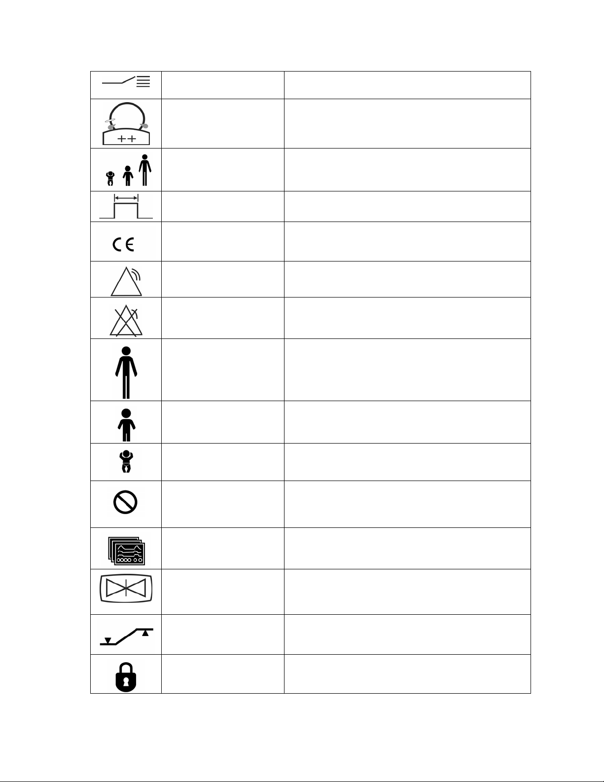
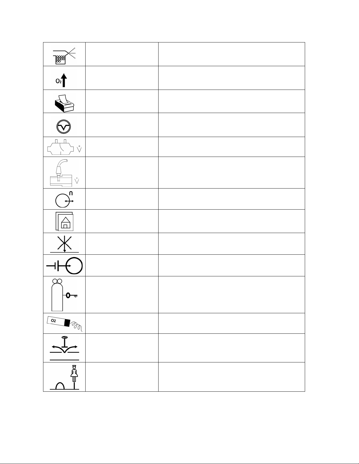
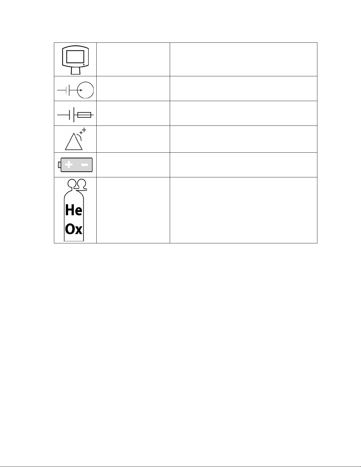
Equipment Symbols
The following symbols may be reference d o n the ventilator or in accompanying documenta t ion
Symbol Source/Compliance Meaning
Symbol #03-02 IEC 60878
Symbol #5016 IEC 60417
Symbol #5034 IEC 60417
Symbol #01-36 IEC 60878
Symbol #5035 IEC 60417
Symbol #01-37 IEC 60878
Symbol #5019 IEC 60417
Symbol #01-20 IEC 60878
Indicates ATTENTION, consult ACCOMPANYING DOCUMENTS
This symbol indicates a FUSE.
This symbol indicates INPUT.
This symbol indicates OUTPUT
This symbol indicates protective EARTH (ground).
This symbol indicates the EQUIPOTENTIAL connection used to
Symbol #5021 IEC 60417
Symbol # 01-24 IEC 60878
connect various parts of the equipment or of a system to the
same potential, not necessarily being the earth (ground) potential
(e.g., for local bonding).
This symbol indicates TYPE B equipment, which indicates
Symbol # 5333 IEC 60417
Symbol #02-03 IEC 60878
Symbol #5032 IEC 60417
Symbol #01-14 IEC 30878
Symbol #5007 IEC 60417
Symbol #01-01 IEC 60878
Symbol #5008 IEC 60417
Symbol #01-02 IEC 60878
equipment that provides a particular degree of protection against
electric shock, particularly with regards to allowable leakage
current and reliability of the protective earth connection.
This symbol is located on the rating plate. It indicates the
equipment is suitable for alternating current.
Indicates ON (Power)
Indicates OFF (Power)
Horizontal return with line feed. Indicates ACCEPT entered
values for a specific field.
Indicates PATIENT EFFORT
ACCEPT
Symbol #0651 ISO 7000
VIASYS Respiratory Care Symbol
VIASYS Respiratory Care symbol
Indicates MANUAL BREATH
VIASYS Respiratory Care Symbol
MAIN SCREEN
Symbol #417 IEC 5102
EVENT READY
1-4 L1524
Page 18
AVEA Ventilator Systems
VIASYS Respiratory Care Symbol
MODE
VIASYS Respiratory Care Symbol
VIASYS Respiratory Care Symbol
VIASYS Respiratory Care Symbol
MDD Directive 93/42/EEC
Symbol #5307 IEC 60417
Symbol #5319 IEC 60417
VIASYS Respiratory Care symbol
ADVANCED SETTINGS
SET-UP for patient Data
SiPAP Duration
CE Mark
ALARM RESET
ALARM SILENCE
ADULT patient
CANCEL
VIASYS Respiratory Care symbol
VIASYS Respiratory Care symbol
Graphical Symbol in general use
internationally for “DO NOT”
VIASYS Respiratory Care symbol
Symbol 5467 IEC 60417
VIASYS Respiratory Care symbol
VIASYS Respiratory Care symbol
PEDIATRIC patient
NEONATAL (Infant) patient
CANCEL, do not accept entered values.
Select DISPLAYED SCREEN function.
FREEZE the current display.
Enable the ALARM LIMITS screen
This symbol indicates a CONTROL LOCK.
L1524
1-5
Page 19
Service Manual
VIASYS Respiratory Care symbol
VIASYS Respiratory Care symbol
VIASYS Respiratory Care symbol
VIASYS Respiratory Care symbol
VIASYS Respiratory Care symbol
VIASYS Respiratory Care symbol
VIASYS Respiratory Care symbol
VIASYS Respiratory Care symbol
NEBULIZER port
Increase OXYGEN
PRINT SCREEN
SUCTION port
VARIABLE ORIFICE FLOW SENSOR connection
HOT WIRE FLOW SENSOR connection
ANALOG IN/OUT connection
Display the MAIN SCREEN
VIASYS Respiratory Care symbol
VIASYS Respiratory Care symbol
VIASYS Respiratory Care symbol
VIASYS Respiratory Care symbol
VIASYS Respiratory Care symbol
VIASYS Respiratory Care symbol
DO NOT BLOCK PORT
EXTERNAL BATTERY connection
Indicates GAS ID port
OXYGEN SENSOR connection
OVERPRESSURE relief
REMOTE NURSE CALL connection
1-6 L1524
Page 20
AVEA Ventilator Systems
VIASYS Respiratory Care symbol
VIASYS Respiratory Care Symbol
VIASYS Respiratory Care Symbol
VIASYS Respiratory Care Symbol
VIASYS Respiratory Care Symbol
VIASYS Respiratory Care Symbol
UNIVERSAL INTERFACE MONITOR connection
This symbol indicates an EXTERNAL BATTERY INPUT
This symbol indicates an INTERNAL BATTERY FUSE
This symbol indicates ALARM LOUDNESS
Operating on Battery Indicator
Operating on Heliox
L1524
1-7
Page 21

Service Manual
1-8 L1524
Page 22

Service Manual AVEA Ventilator Systems
Chapter 2 Theory of Operation
General Description
AVEA is a software driven, servo-controlled ventilator designed to meet the requirements of neonate to
adult patients. The design intent of the device is to provide a high performance software-driven gas
delivery engine, which is capable of providing a full range of volume and pressure ventilation including
dual limb NIPPV. This affords the flexibility of developing new modes of ventilation with no impact to
the basic gas delivery engine. In addition, the device will contain a graphical user interfac e (GUI) that
utilizes a 12.1-inch SVGA color LCD screen with integral touch screen. The GUI will be used to change
settings and operating parameters as well as providing real time waveforms, digital monitors, and
alarms. The device also contains an internal battery that serves as a backup in case of loss of hospital
AC power. The Custom Cart may be equipped with tank holder, external batteries and battery tray for
use of the AVEA during inter-facility transport .
There are three models of AVEA; comprehensive, plus and standard. These are shown in table 2.1
based on the same basic platform. Additional models may be developed in the future by adding or
removing software and/or hardware features to the existing platform.
The AVEA is a fourth generation, servo-controlled, software-driven ventilator. It has a dynamic range of
breathing gas delivery that provides for neonatal through adult patients. Its revolutionary user interfac e
module (UIM) provides maximum flexibility with simple operator interaction. It has a flat panel color
LCD with real time graphic displays and digital monitoring capabilities, a touch screen for eas y
interaction, membrane keys and a dial for changing settings and operating parameters. A precision gas
delivery engine with servo controlled active inhalation and exhalation improves performance over
previous generations.
The AVEA has been designed to function using most commonly available accessories. It is easy to
clean and its design does not allow liquids to pool on the casing, reducing the likelihood of fluid leakage
into the body of the ventilator.
L1524
2-1
Page 23

Service Manual
There are three models of AVEA to choose from: The Comprehensive, Plus, and the Standard. The
following matrix details the standard and optional functions available with eac h model.
Functions & Accessories Standard Plus Comprehensive
Modes
Proximal Hot Wire Flow Sensing
Synchronized Nebulizer
24 Hour Trending
Internal Battery
Full Color Graphics Display
Loops and Waveforms
Standard Cart
Proximal Variable Orifice flow sensing
Proximal Airway Pressure Monitoring
Tracheal Pressure Monitoring
Esophageal Pressure Balloon
Internal Compressor
Heliox Delivery
Optional Functions & Accessories
Custom Cart Option Option Included
External Battery (on custom cart only) Option Option Option
Gas Tank Holder (on either cart) Option Option Option
Internal Compressor Option Option Included
All All All
Heliox Delivery Option Option Included
2-2 L1524
Page 24

AVEA Ventilator Systems
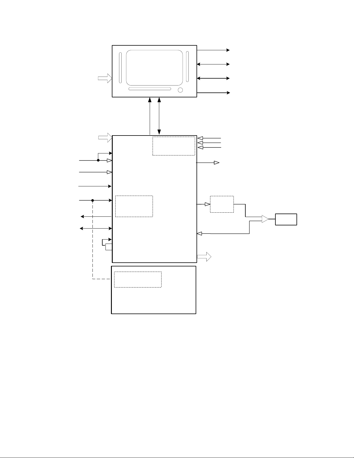
High Level Design
AVEA has been designed with three basic modules, the user interface module (UIM), the pneumatics
module (PM), and the stand (see Figure 1). The UIM contains a graphic al user int erfac e (GUI) which
utilizes a 12.1-inch SVGA color LCD screen with integral touch screen. The UIM also contains a control
PCB that has two microprocessors, control and monitor. The monitor processor manages the GUI,
while the control processor has the real time control system that controls all of the mechanical valves in
the PM. The UIM communicates with the PM via a high-speed serial channel (HSSC). The HSSC also
provides power to the UIM.
The pneumatics module (PM) contains all of the m echanical valves, sensors, analog electronics, power
supply including the internal batteries, and the optional internal compressor. The pneumatics module
takes high-pressure air or 80/20 heliox and oxygen from an external wall source or other high-pressure
source. It filters the gas and blends them through a step per motor controlled blender according to the
front panel settings. It then delivers the appropriate pressure or volume via a high-speed proportional
solenoid with flow sensor feedback. The high-speed control system occurs every 2 msec and is
computed in the control microprocessor in the UIM. The deli vered gas flows to the patient through a
safety valve that has a mechanical over pressure relief valve as well as a sub-ambient valve. The gas is
forced into the patient by closing the servo-controlled voice coil exhalation valve, which is also
controlled by the control microprocessor in the UIM. The patient is a llowed to exhale by the voice coil
exhalation valve, which also maintains baseline pressure or PEEP. The exhaled gas exits the patient
through the expiratory limb of the patient circuit to an inte gral heated expiratory filter to an external flow
sensor and out the exhalation valve to ambient air.
The pneumatics module has several additional capabilities. First it uses either air or 80/20 heliox for an
input gas, and corrects all blending, volume delivery, volume monitoring and alarming, and FiO
monitoring and alarming based on the correct gas density. The system knows what the gas is, by a
patent pending gas ID that identifies the appropr iate inlet DISS fitting with the gas that is being
delivered, which creates an inherently safer system for delivering heliox. The second capability is the
optional back up compressor that is battery backed up for a minimum of 30 minutes by a fully charged
internal battery, which allows for uninterrupted ventilation during a loss of AC power. The third feature is
the ability to monitor volume either at the expiratory limb of the ma chine or at the patient wye. This
allows for more accurate patient monitoring especially in infants while allowi ng the convenience of an
expiratory limb flow sensor protected by a heated filter. Fina lly, the fourth feature is the ability to
measure tracheal and esophageal pressures, which is currently commercially available only on other
VIASYS (Bear/Bird) ventilators.
The stand is used to support the ventilator at an ergonomically correct height. It may contain an optional
external battery for extended use with AC power (custom stand only). It also has an optional O
bracket so that the unit can be used without wal l oxygen during inter-hospital transport. The st and does
not contain active electronic or mechanical components other than the optional external batteries, which
are charged when connected to A/C Power.
2
tank
2
L1524
2-3
Page 25
Service Manual
Printer
User Input
INTERFACE
MODULE
Power
USER
(UIM)
High
Speed
Serial
Channel
(HSSC)
RS232 x 2
MIB
VGA
Air/Heliox
O2 Supply
AC Power
24 VDC
Nurse Call
Analog I/O,
ILV
Ambient Air
Gas ID
O2
sensor
COMPRESSOR
(Optional)
PNEUMATICS MODULE
EXTERNAL BATTERY
(Optional)
Enhanced Pt.
Monitors
(Optional)
Pes
Paux
Faw
Nebulizer
Drive gas
Humidfier
(Optional)
Exhaled Gas
from patient
Exhaust,
Exhaled Flow
Delivered Gas
Patient
CART
Figure 2-3 High End Device Modular Diagram
2-4 L1524
Page 26
AVEA Ventilator Systems
Detail Design
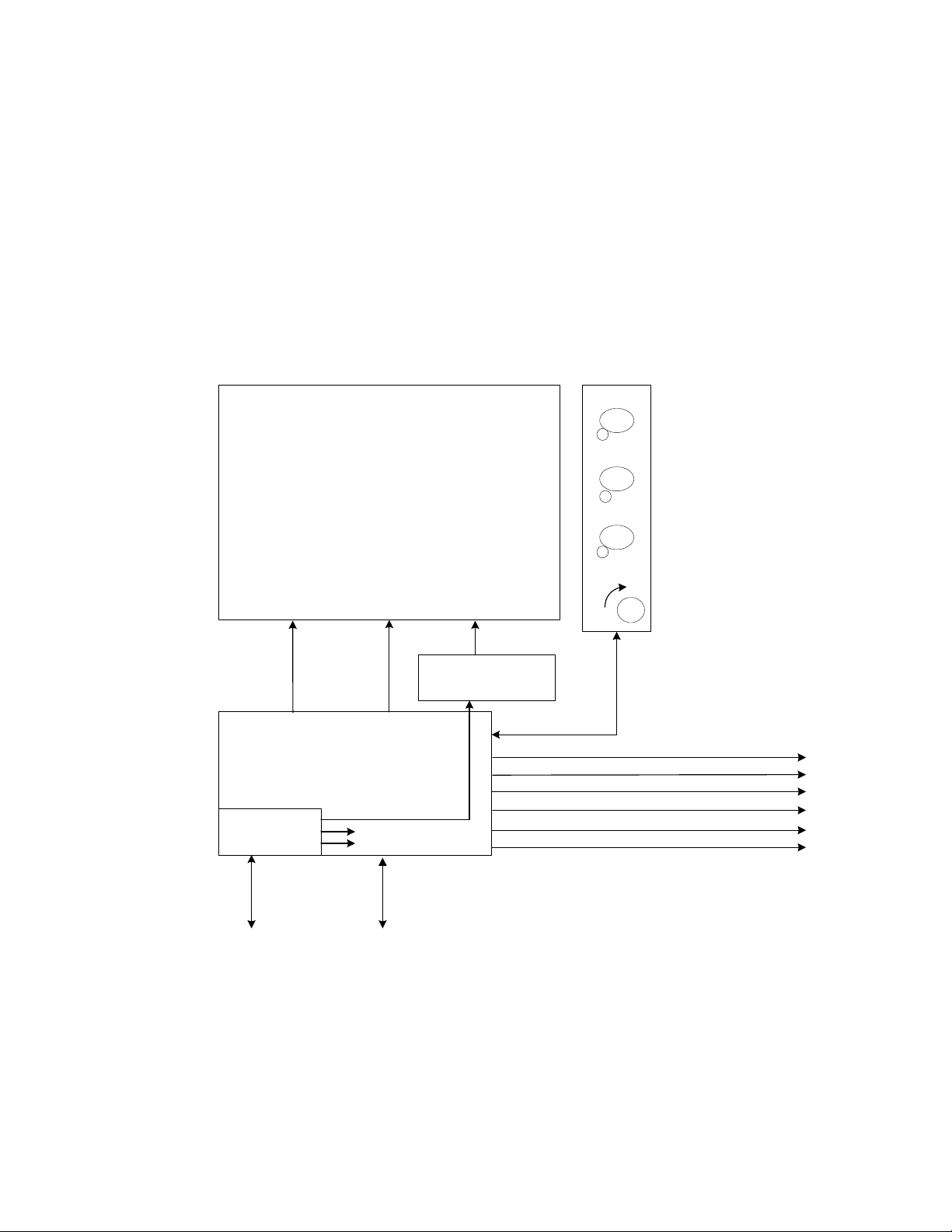
User Interface Module (UIM)
The UIM consists of a 12.1-inch, 800x600 active matrix LCD with an analog resistive touch screen
overlay, a back light inverter, a set of membrane key pan els, an optical encoder, and a Control PCB.
Software and the touch screen provide a set of context sensitive soft keys. The membrane panel
provides a set of hard (permanent) keys for dedicated functions. Selecting the function wit h a soft key
and adjusting the setting using the optical encoder changes a parameter. The parameter is accepted or
canceled by pressing the appropriate membrane key.
LCD & TOUCHSCREEN
(1 & 2)
(3 & 4)
BACK LIGHT AC VOLTAGE
DIGITAL
CONTROL PCB
(7)
DC-DC
CONVERTERS
24VDC
TOUCH
SCREEN
5V
5V, PRN PORT
3.3V, DIG LOGIC
BACK LIGHT INVERTER
HIGH SPEED
(6)
SERIAL
DIGITAL
UNIVERSAL SERIAL BUS (FUTURE)
Figure 2-4 User Interface Design Module Block Diagram
MEMBRANE PANEL WITH
(5)
EMBEDDED LED'S
PRINTER
RS232
RS232
RS232 (MIB)
(CRT)
L1524
2-5
Page 27

Service Manual
The UIM performs all ventilator control functions, gas cal c ulations, monitoring and user interface
functions. The UIM uses a Graphical User Interface (GUI) via the active matrix SVGA LCD and resistive
touch screen to provide system and patient information to the user and to allow the user to modify
ventilator settings. The Control PCB (with two micro-controllers, RAM, ROM and support electronics)
provides all ventilator functions. The Control micr o-controller (MCU) performs all gas calculations;
controls all valves, solenoids, and electronics required to deliver blended gas to the patient. The
Monitor MCU handles all user interface requirements, including updating the active m atrix liquid crystal
display (LCD), monitoring the membrane keypad, analog resistive touch screen, and optical encoder for
activity. The Monitor MCU also performs all the input/output functions of the UIM, including RS-232,
printer, video output, and communication to patient monitors. Communication between the Control and
Monitor MCU’s is accomplished via an 8 bit dual port SRAM. In addition, both MPU's monitor each
other and both are independently capable of activating the fail safe system.
The UIM is self-contained and is tethered to the pneumatics module with a high-speed data and power
cable. All valves are contained in the pneumatics module; the control MCU controls all ventilator
functions via the high-speed serial channel (HSSC). The Monitor MCU provides additional input/output
functions contained in the ventilator. These functions include analog outputs, independent lung
ventilation, and nurse call and are updated by the Monitor MCU via the HSSC.
Liquid Crystal Display
The liquid crystal display (LCD) provides graphical and digital feedback to the clinician. The panel is a
12.1” SVGA, 800x600 pixel, active matrix LCD. The LC D is used to implement the graphical user
interface (GUI). It provides all of the adjustable controls and alarms, as well as displays waveforms,
loops, digital monitors and alarm status in real time.
Touch Screen
The touch screen in conjunction with the LCD provides a set of software configurable soft keys. The
software allows the keys to be context sensitive. The touch screen is a 12.1” analog resistive overlay on
a piece of glass, which is placed over the LCD. It has a resolution of 1024x1024. Physica lly the touch
screen, consists of two opposing transparent resistive layers separated by insulating spacers. Actuation
brings the two opposing layers into electrical contact. The Y coordinate is determ ined by applying a
voltage from top to bottom on the top resistive layer. This creates a voltage gradient across this layer.
The point of contact forms a voltage divider, which is read b y the analog-to-digital converter. The X
coordinate is determined by applying a voltage from left to right on the bottom resistive layer. Again this
creates a voltage gradient and the point of contact forms a divider, which is read with an analog-todigital converter.
Membrane Panel
The membrane panel provides a set of permane nt d edicated keys, which allow the clinician to change
certain ventilator functions. The membrane panel will provide visual status to the clinician via embedded
light emitting diodes (LEDs). The membrane panel consists of membrane switches, which are read by
the monitor CPU. The switches form a matrix of rows and columns. A key closure causes an interrupt to
the monitor CPU, which responds by scanning the key matrix to determine which key has been
pressed.
Light Emitting Diodes (LEDs)
Some of the membrane keys require LED’s to indicate when the key is active. The LED’s are
embedded into the membrane panels.
2-6 L1524
Page 28

AVEA Ventilator Systems
Optical Encoder
The optical encoder allows the clinician to change settings. The setting to be changed is selected by
pressing a soft key on the LCD and then turning the optical encoder to change the value. When the
encoder is rotated two pulse streams ar e generated, phase A and B. When the encoder is turned
clockwise, phase A leads B by 90 degrees. When the direction is counter clockwise, phase B leads A
by 90 degrees. The electronics uses the pha s e information to drive an up-down counter, which is read
by the monitor CPU. The optical encoder is not interrupt-driven and therefore must be polled by the
monitor CPU.
Back Light Inverter
The back light inverter converts 5 VDC into the high frequency AC voltage necessary to power the LCD
back light, which is used to illuminate the LCD.
Control PCB
The control PCB consists of two micro-controllers, the control CPU and the monitor CPU, both of which
are 100 MHz ELAN 410’s. The control and associated circuitry (RAM, ROM, etc) micro controllers
perform all ventilator control functions including the 2 msec closed loop flow control servo and the 2
msec closed loop exhalation valve control servo. The monitor micro-controller manages the GUI and
performs all user input and output including the RS-232 ports, printer port, video out, and MIB port. The
two processors communicate with each other via a dual port RAM. The control processor
communicates with the pneumatics module via a high-speed serial channel (HSSC - 4 Mbits/sec).
Each processor has 8 Mbytes of DRAM, and one Mbyte of flash memory for program storage. In
addition, the monitor circuitry also has a second one Mbyte of flash memory for saving control settings
and trended data for clinical parameters. The control PCB also contains a DC-to-DC converter to
regulate the incoming 24 VDC to the voltages used by the UIM. Finally, the control PCB also contains
all of the circuitry necessary to scan the membrane panels, touch screen, and optical encoder, a s well
as the video controller necessary to drive the SVGA LC D screen.
L1524
2-7
Page 29
Service Manual
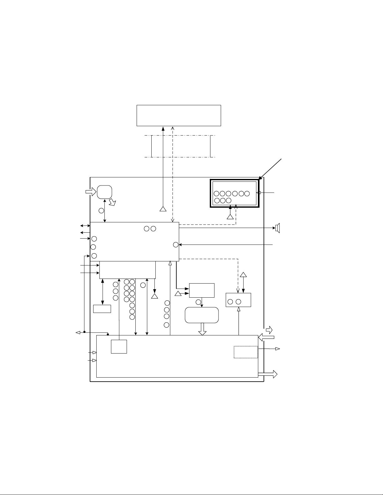
Pneumatics Module
The pneumatics module (PM) consists of a power supply system including internal NiMH batteries, a
transducer/ communication/alarm PCB (TCA PCB), the pneumatics, a heated expiratory system, a fan,
an optional internal compressor, a built-in nebulizer system, and an audible alarm. The PM
communicates with the UIM (User Interface Module) via the HSSC described above.
User Interface Module
(UIM)
Ambient
Analog I/O,
ILV
Nurse Call
Gas ID
AC Power
24 VDC
Sensor
O2 supply
Air/Heliox
SHIELDED
CABLE
Air
Fan
29
10
Transducer/Comm./Alarm (TCA)
18
7
PCB
DC
Power
21
9
High
Speed
Serial
Channel
Enhanced Pt.Monitoring (EPM)
PCB (Optional)
14
15
35
1
HSSC
31363417
16
39
1
Future software option.
Faw, Ptr, Pes,
Paw
Alarm
12
HW Flow
HSSC
Power/Driver
PCB
26
1
2
13
Battery
O
2
222027
23
25
24
28
32
33
37
38
1
DC
Power
RPM
Propotional
Voltage
Compr.Driver
1
1
2
3
13
PCB
(optional)
30
Compressor
System
(optional)
Insp. Flow PCB
19
11
1
Exhaust
3 x
Pres.
PCB
PNEUMATICS
Nebulizer
(Optional)
Exhaled Flow
Neb. gas
Patient
Flow
Reference: Pneumatic Schematic P/N 51K-09742 Rev X1
Figure 2-5 Pneumatics Module Block Diagram
2-8 L1524
Page 30

AVEA Ventilator Systems
Power Supply System
The power supply system, consists of a power inlet module, and a medical grade 350-watt power
supply, the power driver PCB, and a set of internal 12 VDC NiMH batteries connected in series. The
power inlet system accepts a standard IEC medical grade power cord and allows the system to be
configured externally for use with 100 to 240 VAC 5 0/60 Hz power. AC power is converted to 34 VDC
by the internal medical grade power supp ly, which is also power factor corrected. The power driver PCB
converts the 34 VDC from the power supply or the 24 VDC from the internal or external batteries to the
appropriate voltages used by the rest of th e system. The power driver PCB also contains the charging
circuit for both the internal and external batteries, as well as the drivers for the flow control, exhalation
valve, and multiple solenoids. The internal 4.5 Ah NiMH batteries can power the entire system including
the internal compressor for 30 minutes, or 2 hours without the compressor. With the external 17 Ah lead
acid batteries combined with the internal battery powers the entire system, including compressor, will
run for 2 hours on batteries, and greater than 8 hours without compressor.
Transducer/Alarm PCB (TCA PCB)
The TCA PCB consists of circuitry for the audible alarm, the wy e hot wire flow sensor, the gas ID, the
inspiratory and expiratory pressure transducers, the source gas pressure transducers, the exhaled flow
sensor, the FiO2 cell, and communications with the UIM. It also contains the nurse call, and analog
input and output.
A 68HC705 micro-controller is used to generate ala r m waveforms for an ASTM F1463-93 compliant
alarm. A super capacitor is used to provide a minimum if 120 seconds of power without wall AC or a
battery.
Analog circuitry is provided to signal condition the wye Hot Wire Flow Sensor signal and a 12 bit ADC is
used to digitize the signal. A Flow Sensor Fail s ignal is provided to allow the Control Process or to
determine when the flow sensor wire is broken. The Flow Sensor EEPROM is SPI bus compatible and
is read at power up and when a Flow Sensor is co nnected.
The air inlet fitting contains a resistor for determining which gas source is connected to the Air inlet, Air
( 5K ohm) or Heliox (10K ohm). The type of gas connected is determined with a resistor divider, one
half of the divider is contained in a connector and the other half is located on the TCA. The resistor
contained in the connector is different for each gas source and therefore produces a different voltage
output from the divider. The output of the divider is read via an ADC.
Inspiratory and expiratory pressure transducers and associated signal conditioning are digitized on the
TCA PCB. The control processor reads the digitized data via the HSSC. The air, oxygen, and blended
gas pressure transducers and associated signal conditioning are on separate PCBs for ease of
mounting. The amplified signals are cabled to the TCA where they are digitized and communicated to
the control processor via the HSSC.
Exhaled flow is measured with a VARFLEX
a variable orifice with pressure taps on either sid e of th e orifice. The TCA uses a low-pressure
pressure transducer and analog circuitry to measure the flow proportional pressure drop across the
orifice.
Integrated circuit temperature sensors are signal conditioned and digitized by the TCA electronics. The
exhalation and ambient temperature sens ors are cabled to the TCA PCB. The output of oxygen cell is
also signal conditioned and digitize d on the TCA.
®
Exhaled Flow Sensor. The VARFLEX® Flow Sensor uses
There are four 10-bit analog output channels on the TCA for pressure, flow, volume, and breath p hase
respectively. They have a full scale of 0 to 5 VDC with 10- bit resolution. In addition, there are 8
programmable analog inputs that can be used to display external signals. They are digiti zed with a 10
bit DAC, and are scalable from 0 to 1VDC, 0 to 5 VDC, an d 0 to 10 VDC.
L1524
2-9
Page 31

Service Manual
Finally, there is a nurse call output that can be configured as either normally open or normally clos ed.
The nurse call shall be activated for all medium and high priority alarms except when al ar m silenc e is
activated.
Pneumatics-Gas Delivery Engine
The GDE (Gas Delivery Engine) receives and conditi ons supplied Oxygen, Air, or Heliox from an
external and/or internal (compressor) sources. It then mixes the gas to the concentration required and
delivers the desired flow or pressure to the patient.
The Gas Delivery Engine begins with the Inlet Pneumatics. The Inlet Pneumatics accepts clean O
or Air alternate external gas; it provides extra filtrati on and regulates air and O
gas before entering the
2
Oxygen Blender. The Oxygen Blender mixes the gases to the desired concentration before reaching
the Flow Control Valve. The Flow Control Valve controls the flow rate of the gas mixture to the patient.
Between the Oxygen Blender and Flow Control Valve, the Accumulator System is installed to provide
peak flow capacity. The Flow Sensor provides informati on about the actual inspiratory flow for closed
loop servo control. The gas is then delivered to the patient through the Safety/Relief Valve and Outlet
Manifold.
Compressor
Flow
(Optional)
Air/Heliox
Oxygen
Inlet
Pneumatics
Oxygen
Blender
Accumulator
System
Flow Control
Valve
Flow Sensor
Safety/Relief
Valve &
Manifold
Figure 2-6 Gas Delivery Engine Block Diagram
Inlet System
The Inlet Pneumatics conditions and monitors the air, oxygen, and/or helium-oxygen mix supplies
entering the ventilator. The Inlet Pneumatics has Inlet Filters that remove aerosol and particulate
contaminants from the incoming gas supp lies. The downstream Air Regulator and O
Relay
2
combination is used to provide balanced supply pressure to the gas blending system. The Air
Regulator reduces the air supply pressure to 11.0 PSIG and pilots the O
Relay to track at this same
2
pressure. This system automatically regulates to 9.5 PSIG when the optional internal c ompressor is
being used.
, Air,
2
Patient
Flow
In the event the supply air pressure falls below the acceptable level, the internal compressor will be
activated to automatically supply air to the blender. Without an optional internal compressor, the
Crossover Solenoid opens delivering high-pressure oxygen to the Air Regulator, allowing the Air
Regulator to supply regulated O
simultaneously moves to the 100% O
pressure to pilot the O2 Relay. In addition, the Oxygen Blender
2
position, so that full flow to the patient is maintained.
2
In the event of an oxygen supply pressure drop below a pressure threshold, the Crossover Solen oid
stays closed, the blender moves to 21% O
, and the regulated air pressure provi des 100% air to the
2
blending system.
2-10 L1524
Page 32

AVEA Ventilator Systems
Oxygen Blender
The Blender receives the supply gases from the Inlet Pneumatics System and blends the two gases to
the user-selected value. It consists of three sub-systems, valve, stepper motor, and drive electronics.
The Oxygen Blender PCB provides the electronics needed to control the Oxygen Blender stepper
motor. The stepper motor controls the oxygen blender and is stepped in 1.8-degree increments. The
Blender has a disk, which is positioned during cali bration. One end of the disk will interrupt the optical
interrupter when the valve position is closed an d the other end will only interrupt in case the Blender
goes approximately one full revolution due to loss of position. An EEPROM will be used to store th e
number of steps required to travel from the home position to the full open position of the valve, the PCB
revision, and manufacturing date.
Accumulator
The Accumulator stores blended gas supplied from either regulated wall gas or an optional internal
compressor. The accumulator provides the capability to achieve volume capacity at relatively lo wer
pressure, resulting in lower system power requirements. It stores blended gas during patient exhalatio n
cycles which maximizes system efficiency. The Accumulator gas pressur e cycles between 3 and 11
PSIG depending on the Tidal Volume. The system efficiency is improved because a smaller
compressor can be used to meet Tidal Volume while the accumulator provides the extra gas needed to
meet the patient’s peak flow demand. A 6-L/MIN accumulator ble ed orifice allows gas concentration in
the accumulator to match the oxygen blender setting in a maximum time of 1 minute. A pressure relief
valve will provide protection from pressure exceeding 12 PSIG to the accumulator.
Flow Control System
The Flow Control System provides the desired flow rate of gas to the patient. Real time feedback from
the Flow Sensor through the Control System provid es flow correction in the Flow Control Valve. The
Flow Control System consists of a Proportional Voltage Servo Valve controlled by the real time
measurement (2 ms) of flow through a variable orifice Flow Sensor. The variable orifice effect is
created by a thin circular shaped piece of stainless steel that is mounted from an extended side in the
flow stream. The flow will bend the metal creating a variable orifice. The flow proportional pressure
drop is characterized and used for flow measurement. The Servo Control Electronics/Softwar e
receives and sends the control signals to the Flow Control System Components. Flow Control Valve
adjustments are made for gas temperature, g as density, and backpressure.
Safety/Over Pressure System
The Safety/Pressure Relief Valve prevents over-pressure in the breathing circuit, and provides a
connection between the patient and am bient air during a gas delivery failure from th e Ventilator. A
Check Valve downstream of the Safety/Pressure Relief Valve prevents flow from the patient back into
the Ventilator. Pressure Relief around the Check Valve is accomplished through an orifice installed in
parallel to the Check Valve. The Safety/Relief Valve allows the patient to breathe room air in the event
of a ventilator or power failure. It also acts as an independent relief valve, which limits the maximum
pressure the ventilator can deliver.
L1524
2-11
Page 33

Service Manual
Hour Meter
The Hour Meter provides a means of monitoring the number of hours the ventilator is in use. In addition,
it is used by the ventilator to track compressor hours of operation. A Curtis 201-hour meter is used. The
hour meter is active as long as 5 volts is available. The hour meter outputs a continuous stream of
serial data. The control processor reads the data by synchronizing to the start pulse of the data stream
and then reading each successive bit. The hour meter does not have a visible readout and therefore
must be read by software. The hour meter is hard mounted in the pneumatics module and is cabled to
the TCA PCB.
Heated Expiratory System
The heated expiratory system consists of a heated filter contained in a chamber with a micro-controller
controlled heater, a water collector, an exhalation flow sens or, and a servo-controlled exhalation valve.
The expiratory system is located at the end of the patient circuit; the Exhalation Valve regulates gas
flow out of the patient circuit. Diaphragm position of the voice coil type active Exhalation Valve controls
the exiting gas flow rate and patient circuit press ure with precision. Pressure feedback data is sent to
the Electronic Control Unit continuously, which interprets the data, and based upon current ventilator
settings, signals back to position the Exhalation Valve Diaphragm. Since the ventilator will be used in
neonate, pediatric and adult ranges, the exhal ation servo can be optimized for each circuit type to be
used. The Water Collector and Filter remove contami nates from the gas flow before they reach the
Flow Sensor, Exhalation Valve, or the environment. Als o, warm air exhausts through the Exhalation
System enclosure to the atmosphere. The system incorporates a resettable fuse.
Fan
The expiratory flow sensor determines flow by measuring the pressure difference across a variable
orifice. The variable orifice is created with a thin circular shaped piece of stainless steel th at is mounted
on a hinge in the flow stream from an extended side. As flow increases and decreases the hinged flap
creates the variable orifice effect. The pressure drop across the orifice is measured by a press ure
transducer on the TCA and converted to flow by the software in the control micro-controller.
As stated earlier, the exhalation valve is a voice co il with a diaphragm. The exhalation valve controls
circuit pressure, permits only one-way flow, and provides pressure relief above a set level durin g
inspiration. The exhalation valve is controlled with a closed loop servo contained in the control microcontroller and is updated every 2 msec.
The water collector stores water that condenses in the expiratory limb of th e patient circuit protecting
the filter and exhalation valve system. The water collector consists of a vial and an inlet and outlet
shaped fitting. A male 22 mm outside taper (15mm inside ta per) connector is provided for the patient
circuit connection and a 22 mm female connector is used for the heated filter.
The bacteria filter removes particles from the gas that exceed 0.3µm in size. The excess water drains
into the water collector reducing the risk of contamination of the exhalation valve system. Warm heated
air flows past the outside surface of the filter reducing condensation in the filter. The filter is an off-theshelf purchased part.
A 40 cfm fan runs at all times to keep the internal tem perature of the pneumatics module as close to
ambient as possible. In addition, the fan forces flow out past the expiratory filter. A heater heats the gas
as it exits in order to heat the filter as described above.
2-12 L1524
Page 34

AVEA Ventilator Systems
Compressor System (Optional)
The Compressor System provides 3 to 9.5 PSIG air pressure to the system when wall air is not
available. The Compressor has two opposing machined aluminum involutes that are called Scrolls.
One scroll orbits a fixed scroll forming air pockets that get progressively smaller as they travel from the
outer to inner regions of the involute, compressing the gas. The shaft rotation from a brushless DC
motor powers the orbiting scroll within the fixed scroll through an eccentric shaft. It operates at 800 to
3,000 RPM using about 100 watts at 24 VDC. A Pressure Servo improves power efficiency and noise
by matching ventilator demand with supplied compressed air. While the accumulator is the device
which handles the peak flow demand, the servo o perates the compressor at a level which matches the
minute ventilation of the patient.
Nebulizer System
The Nebulizer system provides a 10 PSIG source of blended gas for an external nebulizer. The gas will
only be delivered during the inspiratory cycle of a breath so that the delivery of nebulized gas will be
synchronized with the patient's breathing. Most manuf actur ers’ ne buliz ers dra w betwee n 4 and 8 L/MIN
at 10 PSIG. The Nebulizer is disabled during use of the optional internal compressor.
Enhanced Patient Monitoring PCB (Optional-EPM)
The Enhanced Patient Monitoring PCB provides Esophageal and Tracheal pressure monitoring and
VARFLEX
transducers for the esophageal pressure, tra cheal pressure, and wye flow sensing. In addition, it
contains a 12-bit serial ADC to convert the pressures to digital data. The TCA provides the chip select
and solenoid control signals. Three solenoids are used to control the evacuation and filling of the
Esophageal Balloon. Two solenoids are used to provide purge flow and auto zeroing of the flow sensor
pressure transducer.
®
wye flow sensing. The EPM PCB contains all of the signal condition as well as the pressure
L1524
2-13
Page 35

Service Manual
2-14 L1524
Page 36

Service Manual AVEA Ventilator Systems
Chapter 3 Installation Instructions
This chapter provides instructions for installing the AVEA ventilator systems.
Stand Assembly
Standard Cart Assembly Instructions (P/N 15986)
Standard stand carton contents
QUANTITY DESCRIPTION
10 each 5/16” screws
10 each 5/16 “ lock washers
2 each 5/16-18” hex nuts
1 each Drag chain and modified washer
2 each
1 each
1 each
2 pieces
1 each
4 each
4 each
Flat washers for pole
7/16 tube bracelet
Top plate assembly
Stand Posts
Pedestal base
End caps
Casters (2 with brake, 2 without brake)
Tools required
1/2“ open end socket
3/16” Allen wrench or driver
1. Remove the contents of carton.
2. Attach the base to the pedestal using the 5/16” screws, washers and nuts as shown in Figure
3.1. The anti-static drag chain may be attached to either screw.
3. Attach the pole to the assembly using the 5/16” screws and washers (refer to Figure 3.1).
L1524
3-1
Page 37

Service Manual
4. Attach the top plate to the pedestal using the 5/16” screws and washers (refer to Figure 3.1).
(5x) 5/16-18 x 1” screw and (4X) 5/16
X 1” screw & washer
Thumbscrew
(2X) 5/16 X 1”
screw, flat washer &
lock washer
Top plate
Pedestal
Pole
Base
Figure 3-1 Assembling the Stand
3-2 L1524
Page 38

AVEA Ventilator Systems
5. Place AVEA Ventilator on top plate, align thumbscrews (4) and lightly start all thumbscrews to
locate AVEA Ventilator (refer to figure 3.2). Fully tighten (4) thumbscrews to secure AVEA
Ventilator.
5/16 X 1” screw and
washer
5/16-18 x 1” screw
5/16 X 1” screw nut and washer
Figure 3-2 Bottom of stand
Anti-static drag chain
5/16-18 x 1” screw
L1524
3-3
Page 39

Service Manual
Comprehensive Assembly Instructions
Refers to P/N 33976
1. Open main carton.
2. Remove the center carton that contains the pedestal, hardware and instructions and open.
3. Remove second carton that contains top plate/pole and set aside.
4. Remove the 4-legged base assembly from carton and set base on the floor as shown in Figure 3-3.
Place pedestal onto the base assemb ly as show in Figure 3-3.
Figure 3-3
5. Using the 1/8” Allen wrench provided install and secure the 4 10/24” x ¾” screws along with the 4
star washers.
3-4 L1524
Page 40

AVEA Ventilator Systems
6. Install collar set screw using the 1/8” Allen as shown in Figure 3-4. Next remove pole from Top
Plate carton install and secure the 1” pole using the collar set screw as shown in Figure 3-4.
Figure 3-4
L1524
3-5
Page 41

Service Manual
7. Remove Top Plate and set Top Plate onto the pedestal and pole as shown in Figure 3-5. Using the
3/32” Allen wrench provided install and secure the 4 counter sink screws as shown in Figure 3-5.
Figure 3-5
3-6 L1524
Page 42

AVEA Ventilator Systems
8. Using the 1/8” Allen secure the setscrew of the upper collar into the 1 ” pole as shown in Figure 3-6.
Figure 3-6
Note
If installing external battery pack, proceed to the next section.
9. Place AVEA Ventilator on top plate, align thumbscrews (4) and lightly start all thumbscrews to
locate AVEA Ventilator. Fully tighten (4) thumbscrews to secure AVEA Ventilator.
L1524
3-7
Page 43

Service Manual
Customer Transport Cart Kit P/N 11372
Note: Before installation, verify that the following parts are in your kit:
Description Quantity Part Number
12V lead acid battery 2 16179
Battery tray, screw (10/32 x 5/16)
X2, washer #10 X 2 & nut 10/32
KEPS
Wire harness 1 16217
Literature 1 L2285
Rack Tank Cart Assembly 1 33978
If any parts are missing contact VIASYS AVEA Customer Service at
800-325-0082 or 760-883-7185.
External Battery Installation
1. Unscrew the (4) thumbscrews securing the base to the ventilator body as shown. Lift the ventilator
body and UIM from the wheeled base.
2. Gently set the ventilator down on a secure flat surface (see note on following page).
3. If attached, remove the Gas Tank holder from the base.
33977
Patient Breathing
Gas Outlet
3-8 L1524
Page 44

AVEA Ventilator Systems
Note
Do not rest the ventilator on the patient breathing gas outlet. Resting the weight of the ventilator on this outlet may
cause damage resulting in leaks at the site.
4. Detach the drop-cable portion from the main battery harness as shown.
L1524
3-9
Page 45

Service Manual
5. Remove the two screws holding the face plate between the rear wheels of the AVEA cart and
detach the faceplate.
6. Thread cable harness through the cart pole.
CAUTION
After the cable has been threaded, inspect the cable for any cuts, abrasions or scaring.
3-10 L1524
Page 46

AVEA Ventilator Systems
7 Place the two batteries into the tray as shown in Photo 1.
Red
Figure 3-7
Orange
Dual Orange
8. Attach harness (P/N 16217) to batteries:
• Connect black wire to negative post (black) on the outer right hand side battery
• Connect the dual orange wire to positive post (red) on the inner right hand side battery
• Feed the single orange and single red wires through the center battery support bracket opening to the
left hand side battery area
• Connect the single orange wire to the negative post (black) on the left hand side battery
• Connect the single red wire (positive) to the positive post (red) on left hand side battery
Black
Black
Dual Orange
Single Orange
Single Red
Figure 3-8
L1524
3-11
Page 47

Service Manual
9. Attach monitor PC board (P/N 16105) and wiring:
• Connect 4 pin male Molex™ to the 4 pin female Molex from the b attery harness
Figure 3-9
3-12 L1524
Page 48

AVEA Ventilator Systems
10. Slowly slide the completed battery and tray assembly onto the mount beneath the AVEA stand making sure
that no wires are kinked or scuffed during assembly. Maintain tension on drop cable from top of cart to prevent
kinking at battery tray. Sufficient cable slack must be availabl e at top of cart to make connection at back of
ventilator.
Battery Tray
Mount
11. Attach the faceplate removed earlier in the instructions to the bottom of the battery tray with the hardware
supplied.
12. Re-attach the ventilator body to the stand making sure the external battery cable lays untwisted in the cable
slot and emerges at the rear of the ventilator.
13. Connect the
external battery cable to the connection labeled EXT BATT on the rear panel of the AVEA.
To Rear of
Ventilator
L1524
3-13
Page 49

Service Manual
14 Plug the AVEA into a grounded AC outlet and apply power to the ventilator.
15. Check that the battery status display on the front panel indicates that the ventilator is connected to External
battery power.
Note
The battery status will indicate red immediately after the external batteries are connected and the unit is powered
up. If the batteries are fully charged, the battery status should indicate green (charged) within one hour of
connection. If the batteries are not fully charged, it may take up to 48 hours to indicate green. Refer to your
operator’s manual for recommended battery charging.
“E” Cylinder Bracket Assembly Instructions
This assembly (P/N 33978) is part of kit, P/N 11372.
Quantity Description
1 each Saddle
1 each Center post wit h Ve lcro cylinder straps
2 each 1/4”-20 counter-sink allen-head screws
4 each 1/4”-20 round-head allen screws
4 each Lock washers
Tools Required for Assembly
1 each 5/32” hex wrench/driver
1 each drill with 17/64” bit
1 each ruler
1 each center punch
3-14 L1524
Page 50

AVEA Ventilator Systems
Standard Stand Tank Rack Bracket Installation
Basic Stand Tank Rack Bracket Installation
1. Install the center post in the tank bracket using tw o flathead 1/4"-20 thread screws to secure.
(Figure 3.10)
Figure 3-10 Basic Stand Assembly
Place assembled tank bracket on short side of “H ” stand legs. (Figure 3.11)
Figure 3-11 Tank brackets
NOTE
If there are pre-drilled holes on the “H” stand, skip to Step 8.
2. Place tape measure under bracket. Slide bracket back 3/4” from the edge of the “H” cross piece.
(Figure 3.12)
Figure 3-12 Plate
L1524
3-15
Page 51

Service Manual
3. Center the bracket on the two legs of the “H”. The bracket shoul d be positioned approximately
11/16” from the outside edge of each leg. Recheck the initial 3/4” dimension measurement (refer
to Figure 3.13).
Figure 3-13 Plate Placement
4. Using a pencil, mark location of tank bracket in ce nter of slotted holes on the bracket.
(Figure 3.14).
Figure 3-14 Hole pattern
5. Center punch-marked locations. Before drilling, move rear wheels out of the way to prev ent
damage. (Figure 3.15).
Figure 3-15 Wheel alignment
3-16 L1524
Page 52

AVEA Ventilator Systems
6. Using 17/64” (.265) drill bit, drill through both bracket walls. (Figure 3.16)
7. Remove burrs from drilled holes and insert screw from bottom, guiding through both holes in
tubing and tank bracket. (Figure 3.17)
Figure 3-16 Drill position
Figure 3-17 Deburring
8. Place washer (x4) and nuts (x4) over screws and tighten securely.
Figure 3-18 Tighten
L1524
3-17
Page 53

Service Manual
Assembly Instructions for Comprehensive Cart Tank Rack Bracket
Place the comprehensive stand on a flat surface with the rear of the stand facing up.
Align the saddle with the 4 stand mounting hol es as shown in the photos below (Photo 1 an d 2).
Figure 3-19 Photo 1
Figure 3-20 Photo 2
With the 5/32 Allen wrench, install and secure the 4 screws and lock washers to attach the saddle to
the stand.
CAUTION
Ensure that the saddle is in no way touching the wheels/casters of the stand.
3-18 L1524
Page 54

AVEA Ventilator Systems
AVEA Unpacking Instructions
Introduction
The AVEA is packaged in two parts for safe shipping. A small amount of assembly is required. All
literature and instructions to enable you to safely assemble, set up and check your AVEA are included
in the box with your ventilator.
Unpacking
CAUTION
The AVEA shipping container is designed to be moved or positioned by a forklift or pallet jack only. Do
not attempt to lift or manipulate the container manually as damage or injury could result.
Note
The AVEA Cart shipped with your ventilator must be assembled first. To reduce the risk of damaging the ventilator,
make sure the cart is ready before you unpack the instrument.
Note
Your Operator’s Manual and other important literature are packed beneath the AVEA. Do not discard!
1. Remove all outer securing straps by cutting them. Discard.
2. Open the box and remove the top layer of packagin g material. (Figure 3.21)
Figure 3-21 Box Opening
3. Remove the AVEA accessory box. Place it on a secure surface. (Figure 3.22)
L1524
3-19
Page 55

Service Manual
Figure 3-22 Accessory box removal
4. To remove the cardboard cover, lift the box straight up. Do not pull or tilt the cover until
you are sure it has cleared the ventilator.
5. Remove the protective packaging from the sides of the ventilator and carefully remove
the plastic. (Fig. 3.23)
Figure 3-23 Protective packaging
3-20 L1524
Page 56

AVEA Ventilator Systems
6. Apply the brakes on the cart that has been previ ously assembled by pressing down on
7. With assistance, lift the AVEA from the box and carefully position the unit on the top
the foot pedals. (Fig. 3.24)
Figure 3-24 Brakes
plate assembly of the cart. Secure the unit using the 4 thumbscrews. (Figure 3.25)
Figure 3-25 Thumbscrew Positions
Note
Make sure the external battery cable lays untwisted in the cable slot and emerges at the rear of the ventilator (if
applicable)
8. Loosely secure the 2 thumbscrews in the back of the ventilator, followed by the 2
thumbscrews on the bottom front of the unit. Tighten all 4 screws.
L1524
3-21
Page 57

Service Manual
SETTING UP THE REAR OF THE VENTILATOR
Medical Gas Connector Kit Installation Instructions
Air “Smart” Connector Installation Instructions (P/N 5100040897 DISS)
Note
If you have not ordered the Heliox option, you will receive only the Air smart connector and the appropriate air hose
for your configuration. The Air connector comes pre-assembled with the integral water trap/filter as shown in figure
1. It attaches to the fitting located to the left of the Oxygen cell on the rear panel of the AVEA.
3-22 L1524
Page 58

AVEA Ventilator Systems
CAUTION
Always consult your Operators Manual for instructions and clinical recommendations concerning the use
of AVEA accessories.
Figure 3-26
1. Carefully align and seat the ‘smart’ c onnector pin and the gas fitting.
L1524
3-23
Page 59

Service Manual
2. Tighten the threaded collar on the AVEA onto the male gas fitting of the “smart’ connector
assembly. (Fig. 3.27)
Figure 3-27
Attach the Air hose appropriate for your gas configurat ion. (Fig. 3.28) (Female DISS fitting is shown
here).
Figure 3-28
3-24 L1524
Page 60

AVEA Ventilator Systems
y
A
Air and Heliox Tethered “Smart” Connector Installation
Instructions
(Domestic/ DISS P/N 16131 / International / NIST P/N 16132 )
WARNING
Connection of a gas supply at the Helium-Oxygen mixture inlet that does not contain 20% oxygen can
cause hypoxia or death.
Although an 80/20 mixture of Helium and Oxygen is marketed as medical grade gas, the
Helium/Oxygen gas mixture is not labeled for any specific medical use.
Note
The Heliox “smart” connector comes already tethered to the Air assembly and the “smart” connector attachment
bracket as shown in figure 3.29.
Air smart connector
assembly
Heliox smart connector
assembl
ir tether
Attachment
bracket
Heliox tether
Figure 3-29
L1524
3-25
Page 61

Service Manual
Note
The Heliox “smart” connector is designed for use with an 80/20 Heliox tank only. Only a mixture of 20% oxygen
and 80% Helium can be used as the Heliox gas supply.
1. To assemble the Air/Heliox assembly, first attach the Air “smart” connect or/water trap
assembly to the AVEA rear panel fitting as described in the “Air connector only installation
instructions” section.
2. After attaching the Air connector, remove the Philips screw from the rear of the A VEA.
(Figure 3.30)
Mounting screw on the AVEA
Figure 3-30
3. Insert the screw provided in the kit through the mount on the tethered Heli ox Smart connector
holder. (Fig. 3.31)
Mounting screw in place on the AVEA
Figure 3-31
3-26 L1524
Page 62

AVEA Ventilator Systems
Heliox “Smart” Connector Installation Instructions (DISS
P/N 51000-40918)
Note
The Heliox “smart” connector is designed for use with an 80/20 Heliox tank only. Only a mixture of 20% oxygen
and 80% Helium can be used as the Heliox gas supply. To use the Heliox “smart” connector you must turn off the
air gas supply and unscrew and detach the Air hose from the air smart connector.
CAUTION
The air “smart” connector and water trap are removed as one unit. Do not attempt to separate them as
you may damage the assembly.
Note
Heliox 15’ hose is P/N 50000-40042.
1. To remove the Air “smart connector and w ate r trap, support the assembly with one hand and
loosen the attachment collar. (Figure 3.32)
Figure 3-32
L1524
3-27
Page 63

Service Manual
2. While still supporting the air connector, loosen the collar of the tethered Heliox Connector and
detach it from its storage bracket. (Figure 3.33)
Figure 3-33
3. Position the Air connector onto the same support bracket and tighten down the collar until the
air connecter and water trap are fully secured to the storage bracket.
CAUTION
Make sure that neither the air nor the Heliox tether gets caught in the support collar while you are
tightening it down. If either tether fouls the threads of the collar, the Air connector assembly may not be
adequately secured to the bracket.
Note
Please note that a DISS fitting may be required in addition to those included. These may be obtained from Superior
Products in Cleveland, Ohio (216) 651-9400 P/N MA692.or your gas fittings supplier of choice.
4. Align the Heliox smart connector with the Sm art connector receptacle on the left side of the
AVEA back panel from which you removed the Air connector. Tighten down the collar of the
gas port onto the Heliox fitting. (Figure 3.34)
3-28 L1524
Page 64

AVEA Ventilator Systems
5. The HeO2 cylinder symbol should appear in the lower right hand corner of the user interface
screen.
Figure 3-34
L1524
3-29
Page 65

Service Manual
Connecting the Oxygen Sensor P/N 68289
The oxygen sensor cell is located on the rear panel, between the
two gas fittings. The oxygen sensor cable emerges from the rear
panel directly above the sensor. Caref ully align and then gently
push the connector onto the oxygen sensor until it seats. When a
good connection has been made, slide the protective cover down
and push over the sensor.
Figure 3-35 Connecting the O2 Sensor
Attaching the Gas Hoses
Oxygen Connection
Attach the Oxygen hose to the fitting on the right
of the back panel (see figure 3-36).
Figure 3-36 Connecting the O2 Hose
Heliox Connection
If you have the upgrade for Heliox delivery, attac h the Heliox
hose .to the tethered “Smart” connector fitting on the left of
the back panel as shown in figure 3-37.
The air hose will not attach to the fitting designed for Heliox
and vice versa.
Figure 3-37 Connecting the Heliox Hose
3-30 L1524
Page 66

AVEA Ventilator Systems
WARNING
Allow 90 seconds for the accumulator to purge before initiating patient ventilation with Heliox gas.
WARNING
Connection of a gas supply at the Helium-Oxygen mixture inlet that does not contain 20% oxygen can
cause hypoxia or death.
Although an 80/20 mixture of Helium and Oxygen is marketed as medical grade gas, the
Helium/Oxygen gas mixture is not labeled for any specific medical use.
Attaching the Air Hose
Attach the Air supply hose to the “Smart” connector
fitting with the integral water trap/filter on the left of
the back panel as shown in figure 3-38.
The fitting shown here is a DISS fitting. Fittings
which accept NIST and Air Liquide hoses are also
available from VIASYS.
The air hose will not attach to the fitting designed for
Heliox and vice versa.
Figure 3-38 Attaching the Air Hose to the water trap/filter
Note
The fitting for Air will not accept a Heliox connection and vice versa.
L1524
3-31
Page 67

Service Manual
3-32 L1524
Page 68

Service Manual AVEA Ventilator Systems
Chapter 4 Assembly and Disassembly
General Instructions and Warnings
The removal and installation of major subassemblies requires OVP and possibly calibration. Refer to
chapters 5 and 7 for instructions.
When disassembling or assembling the AVEA, refer to the tubing diagram, P/N 51000-40841, the wiring
diagram P/N 51000-40839 and appropriate schematics and assembly drawings located in Appendix B
of this manual. The illustrations shown here are for reference only, current revisions of these diagrams
and schematics are available to qualified personnel from VIASYS Healthcare, Critical Care Division,
Technical Support.
WARNING
Always take standard ESD precautions when working on AVEA ventilator systems.
Assume that you are adequately earth grounded prior to handling and working inside of the AVEA
ventilator.
Ensure the ventilator is disconnected from the AC power supply before performing repairs or
maintenance. When you remove any of the ventilator covers or panels, disconnect the in ternal battery
“quick release” connector (see figure 3.1) before working on the ventilator. If the ventilator ha s a n external
battery installed, ensure that the e xternal battery is unplugged from the rear panel before proceeding.
Recommended Tools & Equipment
Note
Before using any test equipment [electronic or pneumatic] for calibration procedures, the accuracy of the
instruments must be verified by a testing laboratory. The laboratory master test instruments must be
traceable to the NIST (National Institute of Standards Technology) or equivalent. When variances exist
between the indicated and actual values, the calibration curves [provided for each instrument by the
testing laboratory] must be used to establish the actual correct values. This certification procedure
should be performed at least once every six months. More frequent certification may be required based
on usage.
Long & short Philips screwdrivers
Flat bladed screwdriver
7/8” Nut Driver
11/32” Nut Driver
Digital Volt Meter
Adult test Lung (Siemens) P/N 33754
Adult Patient Circuit (72”) P/N 16045
Infant test lung P/N 34057
Infant Patient Circuit
Pediatric Patient Circuit
Oxygen Analyzer
L1524
4-1
Page 69

Service Manual
Rubber Stopper
Stop Watch
Side cutters
User Interface Module (UIM) P/N 16259 Domestic (P/N 16260
International)
Removal
1. Remove the ‘rubber collar’ located at the UIM rear neck, by grasping one of the two rubber tabs at the
bottom. Pull firmly in an “arcing” motion.
2. Remove (1) Phillips screw from the ‘front arm cover’ located below the UIM. Remove the ‘front a r m
cover’.
3. Remove the two mounting screws now visible inside the ‘back arm cover’. Tilt the UIM down and
remove the ‘back arm cover’.
4. Remove the exhalation filter from the filter well. Using a long Phillips screwdriver, remove the (1)
Phillips screw located at the top of the exhal ation filter assembly well.
5. Remove the (1) Phillips screw located at the exhalation port marked EXH.
6. Remove the (4) 11/32 KEP nuts that secure the ‘plastic top cover’ opening onto the chassis.
7. Remove (2) Phillips screws that secure the ‘plastic top cover’ to the rear chassis.
8. Slide the top ‘plastic top cover’ forward and upward away from the chassis.
9. Remove the (2) Phillips screws and washers that secure the ‘UIM interface cable connector’ on the rear
chassis. Unplug the ‘UIM interface cable connector’.
10. Carefully pull the ‘UIM interface cable connector’ through the ‘plastic top cover’ opening.
11. While continuously supporting the UIM, remove (4) nuts that fasten the UIM onto the ‘support arm’.
User Interface Module (UIM)
Installation
1. While continuously supporting the replacement UIM, position the UIM’s four threaded mo unting studs
into the ‘support arm’, mounting plate and secure it with ( 4) nuts.
2. Feed the ‘UIM interface cable connector’ into the ‘plastic top cover’ opening, towards the rear
of the chassis.
3. Slide the ‘plastic top cover’ back in place.
4. Install (2) Phillips screws and washers into the ‘UIM interface cable connector’ and secure it to
the rear chassis.
5. Install (2) Phillips screws to secure the ‘plastic top cover’ to the rear chassis.
6. Install (1) Phillips screw located at the exhalation port marked EXH.
7. Use (4) 11/32 KEP nuts to secure the ‘plastic top cover’ opening onto the chassis.
8. Using a long Phillips screwdriver, install (1) Phillips screw at the top of the exhalation filter
assembly well. Install the exhalation filter back into the filter well,
9. Tilt the UIM down and install the ‘back arm cover’. Install two mounting screws inside the ‘back
arm cover’ and tighten them.
10. Install the ‘front arm cover’. Install (1) Phillips screw into the ‘front arm cover’ and tighten it.
11. Install the ‘rubber collar’ around the UIM rear neck.
4-2 L1524
Page 70

AVEA Ventilator Systems
WARNING
Always disconnect the white battery quick disconnect once the top cover is removed to prevent injury
and/or damage to the AVEA Ventilator System.
Note
Prior to complete reassembly, UIM may be temporarily installed for
testing and calibration.
Exhalation Filter Assembly/UIM
Removal
1. If installed, remove the exhalation filter assembly.
2. Rotate the metal locking lever on the lower right of the ventilator body forward to an open position.
Remove the exhalation filter assembly from the ventilator body pulling straight down.
3. Remove the rubber collar by grasping one of the two rubber tabs at the bottom. Pull firmly in an
“arcing” motion.
4. Remove the (1) Phillips screw on the front neck cover below the monitor and remove the front arm
cover.
5. Remove the two mounting screws now visible inside the back neck cover.
6. Tilt down the UIM and remove the back neck cover. Remove the (2) Phillips screws and washers
on the molded gray cover connector attached to t he rear panel and unplug the UIM interface
cable.
7. Using a long Phillips screwdriver, remove the (1) Phillips screw located at the top of the exhalation
filter assembly well.
8. Remove the (1) Phillips screw located at the exhalation port marked EXH.
9. Remove the (4) 11/32 KEP nuts on the rounded portion of the molded plastic top cover.
10. While supporting the UIM continuously, remove (4) 3/8 KE P nuts holding the UIM in place on the
aluminum ring.
11. Remove the 2 Phillip head screws from the back of the unit that att ach es the plastic top cover to
the pneumatic module.
12. Remove the UIM, then the plastic top cover.
L1524
4-3
Page 71

Service Manual
Metal Top Cover
Removal
1. With the Plastic Top Cover removed, continue by removing the 19 SEMS screws, (3) on the
left side (5) on the right side and (11) on top.
Note
The screws along the back of the metal top cover are different—flat head.
Note
For ease in removal of these screws it is recommended to use a power screw driver.
2. Remove metal top cover and set aside.
3. Disconnect the internal battery 2 pin Molex connector.
Warning
Assure that the work area is Electro Static Discharge (ESD) protected. The Printed Circuit Board Assemblies
(PCB’s) have integrated circuits (IC’s) that can be severely damaged by static electricity. Work surface must be
certified as anti static or grounded before removing covers and while working on the ventilator. Wear a properly
grounded and tested anti-static strap prior to handling PCB’s.
Gas Delivery Engine P/N 16222A
Gas Delivery Engine Removal
1. Referring to the instructions above, remove the UIM and molded metal top covers
2. Disconnect internal battery.
3. Disconnect the 4-pin connector from the battery monitor board to the gas delivery engine
(51000-40022 Only).
4. Remove the (4) SEMS screws located at each corner of the rear panel.
5. Remove A/C power cord bracket.
6. Cut the tie wrap and remove the metal tubing support bracket and disconnect the tube from
the accumulator outlet by releasing the compression fitting.
7. Completely remove the hose between the gas delivery engine assembly and the scroll
pump/compressor filter.
8. Squeeze to remove the two small ribbon cables near the front of the gas delivery engine
assembly (the 10-pin ribbon cable connector from the flow sensor assembly and the 20-pin
ribbon cable connector from the front interface panel).
4-4 L1524
Page 72

AVEA Ventilator Systems
CAUTION
Never pull on a cable during disconnection. Damage to the connector wiring may result. Always pull on
the connector body to disconnect.
9. Unscrew the luer-lock fittings (the clear yellow tubing from F4, and the black striped tubing
from G4).
Top
Side view
Bottom
Figure 4-1 G4 and F4 luer connections
G4 (high side of expiratory flow and expiratory pressure XDCR 3 and 2)
Clear silicone tubing with black line
Top – goes to the expiratory flow sensor bulkhead
Bottom – goes to the expiratory manifold on the TCA
F4 (low side of expiratory flow)
Clear silicone tubing
Top – goes to the expiratory V sensor bulkhead
Bottom – goes to the expiratory manifold on the TCA
E4
Yellow tubing
Top – inspiratory pressure line that goes to the SOPR manifold
Bottom – inspiratory pressure that goes to the transduc er on the TCA ( XDCR 1)
10. Disconnect the yellow bleed tubing from C4 by releasi ng the compression fitting.
11. Disconnect the large blue tubing to the nebulizer from H4 by releasing the compression fitting.
L1524
4-5
Page 73

Service Manual
Figure 4-2 C4 and H4 compression fittings
Note: With replacement of the GDE, the position jumper J3 on the Secondary Alarm Board
must be reviewed for proper placement.
G4 (high side of expiratory flow and expiratory pressure XDCR 3 and 2)
Clear silicone tubing with black line
Top – goes to the expiratory flow sensor bulkhead
Bottom – goes to the expiratory manifold on the TCA
F4 (low side of expiratory flow)
Clear silicone tubing
Top – goes to the expiratory V sensor bulkhead
Bottom – goes to the expiratory manifold on the TCA
E4
Yellow tubing
Top – inspiratory pressure line that goes to the SOPR manifold
Bottom – inspiratory pressure that goes to the transduc er on the TCA ( XDCR 1)
4-6 L1524
Page 74

AVEA Ventilator Systems
12. Disconnect the yellow tubing from (D4) that feeds the EPM board.
13. Loosen the 11/32 nut securing the assembly to the base at the bottom front left.
14. Ensure all cables and tubing are tucked into the g as delivery engine assembly and slide the
assembly out of the unit towards the rear. You will here a distinct “pop” as the assembly
disconnects from the driver transition board connection.
15. Remove the power cord support bracket.
Note
You may need to pull firmly as you slide out the gas delivery engine assembly because it is attached to the 120-pin
connector on the driver transition board.
If you are removing Gas Delivery Engine P/N 510000-40022 please continue with the next step. If you are removing
Gas Delivery Engine P/N 16222 please continue at step number 1 of Installation.
16. Locate the internal battery pack and cut the 2 purple wires located at the
battery pack to 1.5” (inches).
17. Fold back onto itself, 1 of the wires that has been cut ¼” (inch).
18. Cut the wire that was not folded even with the wire that was folded, so that they are now even
in length.
19. Cut a piece of heat shrink tube that has been suppli ed to I” (inch) in length.
20. Slide both purple wires that have been folded and cut into the heat s hrink tube.
21. Ensure that both wires are inside the heat shrink tube and that neither wire is showing through
the end of the heat shrink tube.
22. Using a heat gun or equivalent device, warm the heat shr ink tube until it shrinks tight to the 2
purple wires that have been cut and folded previously.
23. Locate the Compressor power board located next to the compressor pump.
24. Remove the one 11/32” nut securing the ground wire from the compressor power board.
25. Remove the 2 11/32” nuts securing the compressor power board to the unit case.
26. Raise the compressor board up and away from the unit enough to allow disconnection of the 2
wire harnesses.
27. Cut the ground wire 1”(inch) from the compressor power board.
28. Fold back onto itself, the cut wire ¼” (inch) that is attached to the Compressor Board.
29. Cut a piece of heat shrink tube that has been suppli ed to I” (inch) in length.
30. Slide the wire that has been folded and cut into the heat shrink tube.
31. Using a heat gun or equivalent device, warm the heat shrink tube until it shrinks tight to the
wire that was cut and folded previously.
32. Reconnect the 2 wire connectors to the Compressor Power Board.
33. Re-install the Compressor Power Board to the unit case using the 2 11/32” (inch) nuts.
34. Cut all tie straps securing Battery Monitor Board P/N 16105.
35. Disconnect the 2 pin connector of the battery monitor board from the 2 pin connector
containing wires #12 and #13.
L1524
4-7
Page 75

Service Manual
36. Disconnect the 4 pin connector from the battery monitor board to the battery.
37. Disconnect wire #14 from the black wire of the battery monitor board.
38. Disconnect the 2 wires from the fuse holder. The battery monitor board will now be free to
remove from the unit.
39. Connect wire # 14 to the straight terminal of the fuse holder.
40. Connect wire harness (internal battery upgrade cable assembly) P/N 16243 2 pin connector to
the 2 pin connector containing wires # 12 and #13. Secure using cable tie P/N 05038.
41. Connect the black wire from cable harness P/N 16243 to the right-angle terminal connector of
the fuse holder.
42. Connect the 4 pin connector of the internal battery to the 4 pin connector of P/N 16243.
Secure 4 pin connector using cable tie P/N 05038.
Installation
WARNING
Prior to re-installing the GDE, insure that C31 is not touching the Flow Control Valve or that there is
insulation material between the two. (C31 is the orange capacitor located closest to the top of the FCV).
1. Ensure all cables and tubing are tucked into the gas delivery engine assembly and slide it as far
into the unit as required to hold the assembly. Do n ot yet connect the assembly to the driver
transition board.
2. Connect yellow hose (D4) to the EPM board.
3. Connect the tubing from the EPM board into C4 by inserting into the compression fitting.
4. Connect the yellow bleed tubing from the sensor assembly; the clear yellow tubing to F4, and the
blue tubing to G4. To connect into the luer lock fittings, twist and push.
5. Connect the clear tubing from the sensor assembly to F4 luer lock fitting, and the black striped
tubing to G4 luer lock fitting.
6. Connect the two ribbon cables located at the front of the ventilator (the 10-pin
ribbon cable to J17 and the 20-pin ribbon cable to J16).
7. Connect the 4-pin battery monitor board to the gas delivery engine.
8. Engage the gas delivery engine to the driver transition boa rd by ensuring proper alignment of the
two alignment pins and the connector. Press firmly i nto place.
4-8 L1524
Page 76

AVEA Ventilator Systems
CAUTION
Figure 4-3 Gas Engine Connector on Driv er Transition PCB
It is essential to ensure correct alignment to the 120-pin connector on the driver transition board (see
diagram) before pushing home the gas delivery engine. Failure to do so may result in damage to the
connector and the unit may not power up or operate properly.
9. Attach and secure the (4) SEMS screws on the four corners of the rear panel.
10. Replace the yellow hose from the gas delivery en gine to the compressor filter.
11. Connect yellow hose from the accumulator into the compression fitting. Replace the metal safety
bracket, and secure with a new tie wrap.
12. Tighten the 11/32 nut at bottom right of the Gas Delivery engine and tighten
down.
13. Attach the User Monitor Interface and cable.
Note
Perform the Calibration and Operational Verification Procedure located in the AVEA service manual.
14. Once all tests are preformed, remove the User Interface Module and install the metal cover and all
associated screws.
15. Install plastic top cover and User Interface Module (UIM).
Note
Perform the Extended Service Test (EST) once the unit is completely re-assembled and prior
to patient setup
L1524
4-9
Page 77

Service Manual
Ventilator wheeled base
Removal
1. Unscrew the (4) thumbscrews on attaching the
base to the ventilator body as shown in fi gure 4.4 and
detach from the wheeled base.
Installation
2. Position the ventilator assembly onto the base
by lining up the holes over the 4 spring-loaded
thumbscrews and tighten the thum bscrews.
Internal Batteries P/N 68339A
Removal
1. Referring to the instructions in this chapter, remove the following components:
UIM and the top cover
2. Internal battery fuse holder
3. Disconnect the battery fuse holder by pulling straight back on the two faston connectors.
4. Remove the fuse holder and fuse from the ventilator chassis using pliers to remove nut.
5. Remove the (3) 11/32 KEPS nuts that hold the battery bracket in place; (2) KEPS nuts on the
bottom and (1) on the top.
6. Slide out the retaining bracket and the batteries.
Figure 4-4 Wheeled base
showing attachment points
Figure 4-5 Battery fuse holder & Bracket
4-10 L1524
Page 78

AVEA Ventilator Systems
7. Disconnect the positive and negative
leads from the wire harness that
connects to the driver transition
board.
8. Cut both tie wraps that secure the
battery monitor board and the 4-pin
molex to the batteries.
9. Disconnect the batteries from each
other.
Installation
Figure 4-6 Battery Assembly
1. Cut three 3” stripes of 1” wide double-backed adhesive tape. Place one strip on the bottom of
one battery, and the other two strips on the top and bottom of the other bat t ery.
2. Place the first battery against the chassis and the second battery on top of the first.
3. Secure the batteries into place with the retaining bracket by using (3) 11/32 KEPS nuts; (2)
KEPS nuts on the bottom and (1) on the top.
4. Connect the positive and negative battery leads to the wire harness that connects to the driver
transition board. (These are arranged M-F and F-M so they cannot be wrongly connected)
5. Replace the fuse holder into the front of the chassis.
6. Connect the lug connectors to the two battery fuse terminals using either combination of wires.
7. Referring to the instructions in this chapter, install the following components:
UIM and the top cover.
FUSES
The AVEA has replaceable fuses associated with internal DC, external DC and AC power sources.
Please refer to your present power requirements which are detailed on the rear of the AVEA.
Line Voltage
100/120VAC (2) 250 V 6.35 X 31.75mm 3.15 amp
230/240VAC (2) 250 V 6.35 X 31.75mm 6.3 amp
Fuse Amperage (350 Watt Power Supply) 250 Watt Power Supply
(Viasys P/N 71692)
(Viasys P/N 03490)
1.5 amp
(Viasys P/N 71698)
3.15 amp
(Viasys P/N 71692)
L1524
4-11
Page 79

Service Manual
WARNING
Do not remove or replace fuses or perform any maintenance tasks on the ventilator while your patient is
connected. Always perform these tasks “off patient”.
Battery Fuses
The internal and optional external battery fuses are
10A, 250V 5 x 20 mm fast blow type.
The fuse for the optional external battery is located on
the back panel next to the external battery connector
and is replaceable. The fuse for the internal battery is
located to the right of the UIM connection. To remove
fuses, carefully unscrew with a flat blade screwdriver
and pull out the fuse holder.
Figure 4-7 External Battery Connector & Fuse
External
Battery Fuse
External
Battery
Connector
WARNING
To avoid fire hazard, use only the fuse specified in the ventilator’s parts list or one that is identical in
type, voltage rating, and current rating to the existing fuse.
Mains Fuses
The main AC power fuses are housed within the power entry module located on the back panel. They
are slow blow-type. Check that the correct voltage for your mains sup ply is showing through the
window in the power entry module.
Replacing a Mains Electrical Fuse
Table 4-1 Mains fuses
Line Voltage Fuse Amperage
100/120VAC 250V 6.35 x
3.2A
31.75mm
230/240VAC 250v 6.35 x
1.5A
31.75mm
WARNING
Ensure that the mains power cord is unplugged before attempting to remove or replaces fuses.
To replace mains electrical fuses, refer to figures 4-8 through 4-12 and do the following:
4-12 L1524
Page 80

AVEA Ventilator Systems
1. Unplug the ventilator from the mains AC power source and unplug the power cord from
2. Using a small flat blade screwdriver, pry ope n the cover of the power entry module.
3. Carefully ease the red fuse holder out of the power entry module.
4. The fuse holder contains two identical fuses, either 3.1Amp for (for 100/120 volt lines) or
5. Replace the failed fuse in the fuse holder with a fuse whose type, voltage rating, and
6. Carefully replace the red fuse holder into the power entry module. Check to ensure that
7. Close the power entry module cover and check to make sure that the correct voltage is
the power entry module on the rear of the ventilator.
2.0 Amp (for 230/240 volt lines) as shown in table 6.1.
current rating is identical to the fuses supplied from the factory.
the correct line voltage is uppermost as you re-insert the fuse holder into the
power entry module.
displayed through the window.
L1524
4-13
Page 81

Service Manual
Changing the AC Fuses:
Figure 4-8
Opening the
power
entry module
with a
screwdriver
Figure 4-9
Removing the
fuse holder
Figure 4-10
Fuse holder
showing fuse
placement
Figure 4-11
Fuse-holder
with 230V
label uppermost
for 230/240VAC
systems.
Figure 4-12
closed power
entry module
with 115V
showing in the
window for
100/120 volt
systems
4-14 L1524
Page 82

AVEA Ventilator Systems
Compressor/Scroll Pump P/N 51000-09750A
33928 / Inlet Filter
33929 / Outlet Filter.
Figure 4-13 Compressor/ Scroll Pump
Removal
1. Referring to the instructions in this chapter, remove the following components:
2. Remove high pressure hose from compressor motor at the filter outlet. Move the high
3. Disconnect from A/C power.
4. Disconnect internal battery.
5. Remove the (4) 11/32 KEPS nuts in each corner of the compressor mounting base. Remove
6. Disconnect compressor wiring harness (molex P2) from compressor driver board.
7. Carefully lift compressor pump to clear the power board shield.
8. Access the 12-pin scroll pump connector and disconnect from the driver transition board.
9. Remove the (2) KEPS nuts on the scroll compressor board (1) on the right and (1) on the front,
10. Scroll pump is now completely detached.
11. Remove from the unit and set aside.
Note
UIM and the top cover.
pressure hose out of your working area.
the (1) ground wire located at the front right of the com pressor.
and remove the compressor board.
Compressor power board should be placed in an antistatic bag.
L1524
4-15
Page 83

Service Manual
Installation
1. Slide the compressor/scroll pump in the front right side of the ventilator and position over the (4)
studs.
2. Install ground wire over right front stud and secure with one of the 11/32 KEPS nuts.
3. Secure compressor using the (4) 11/32 KEPS nuts over the (4) studs.
4. Connect 8-pin Molex connector from compressor to compressor driver board.
Note
Ensure the scroll compressor assembly is seated below th e wire that runs from the driver
transition board to the fan and push down the wir e h arness from the driver transition board
under the front of the scroll pump to avoid wedging it between the scroll pump and the chassis
5. Position the scroll compressor board onto two studs and se cure with (2) KEPS nuts; (1) on the right
and (1) on the front. Inlet 33928 / & outlet 33929 / Filters (0.3 mi crons)
6. Reattach the high pressure hose to the filter outl et.
7. Referring to the instructions in this chapter, re-install the following components:
• UIM and the top cover.
Enhanced Patient Monitor (EPM) Board P/N 5100040848A
Removal
1. Referring to the instructions in this chapter, remove the following components:
• UIM and the top cover
• Ventilator assembly (from the base)
2. Remove the flow sensor cover by removing the (3) SEMS screws.
3. Remove the (2) KEPS nuts; the brss colored EMI shield, and blue flex cable.
4. Disconnect the 10-pin ribbon cable from the front of the GDE.
5. Turn the unit on its’ side.
6. Remove (7) Phillips screws; 2 from the lower back panel and (5) from the bottom panel.
7. Remove bottom panel.
8. Remove (2) screws from the top of the front panel.
9. Loosen (2) KEPS nuts from the bottom that hold the front panel.
10. Pull off front panel.
11. Loosen (1) KEPS nut from the bottom and (4) screws on the front panel.
12. Remove the blue tubing from the nebulizer to the front panel.
13. Gently pull the blue ribbon cable through the narr ow slot at the top center fo the front interface
panel and the rest of the wiring through the recesse d compartment in the chassis.
4-16 L1524
Page 84

AVEA Ventilator Systems
CAUTION
Never pull on a cable during disconnecti on.
Installation
Figure 4-14 EPM Board alignment notches
Note
Ensure that you do not pinch any tubing since this can result in damage to the AVEA.
1. Gently feed the blue ribbon cable through the narrow slot at the top center of the front panel and
the wiring through the recessed compartment in th e chassis.
2. Attach the blue tubing from the nebulizer to the front panel.
3. Tighten (1) KEPS nut on the bottom and (4) screws on the front interface panel.
4. Position the front panel and install (2) KEPS nuts on the bottom and (2) screws on the bottom of
the front panel.
5. Position the back panel and install (7) Phillips screws; (2) on the lower back pane l and (5) on the
bottom panel.
6. Turn the unit over.
7. Install the (2) KEPS nuts, the EMI shield, brass bracket and ribbon cable.
8. Attach the flow sensor cover by installing the (3) SEMS screws.
9. Referring to this chapter, install the following components:
Ventilator assembly onto the base
UIM and the top cover
L1524
4-17
Page 85

Service Manual
Fan Assembly P/N 51000-40861
(12 VDC, 550mA)
Removal
1. Referring to the instructions in this ch apter, remove the following components:UIM and the to p
cover.
2. Disconnect the fan cable from the wire harness of the TCA board.
3. Pop off the fan filter cover.
4. Remove the filter and the filter cover.
5. Remove the (4) 2.5” Phillips screws h olding the fan filter housing. Remove the fan assembly
and the fan cover.
Installation
1. Insert the honeycomb shield into the shroud.
2. Insert the fan assembly into the shroud, ensuring the wire assembly is facing towards the
lower outside corner of the ventilator.
3. Align the fan cover on the out side of the chassis and the fan assembly on the insid e using (1)
screw to assist in positioning.
4. Secure both the fan cover and the fan assembly with (4) 2.5” Phillips screws.
5. Connect the fan cable to the TCA wire harness.
6. Tuck the wire harness along side the fan b etween the fan and the outer wall of the unit.
7. Place the filter inside the filter cover so th at the locking tabs face the chassis and snap the
filter cover into place.
8. Referring to the instructions in this chapter, install the following components:
• UIM and the top cover.
4-18 L1524
Page 86

AVEA Ventilator Systems
Power Supply P/N 16388
Tools Required
Phillips #2 screwdriver with 8” shaft
11/32 nut driver
3/8 nut driver
Side cutters
Needle-nosed pliers
Removal
1. Referring to the instructions in this chapter, remove the following components
in the following order:
• UIM and the top cover.
Note
To gain access to the power supply, the aluminum shield under the plastic top cover must also
be removed. There are (19) SEMS screws; (3) on the left, (5) on the right and (11) on top.
• Fan assembly
• EPM board (It is not necessary to remove this board when gaining access to the power
supply. Please see instructions at the end of this procedure).
• Scroll pump/compressor.
2. Cut and remove all cable ties that secure the wire assemblies to the power shield.
3. Disconnect the 5-pin connector at J2.
NOTE
It is suggested to label the (3)wires coming from the 3-pin terminal block as neutral (blue), load (brown)
and ground (green and yellow) as printed on the power supply circuit board.
4. Using a Phillips screwdriver, loosen the screws of the terminal block that secur es wires #1 and #3
and remove.
5. Remove and label blue (neutral) and brown (load) wires on the power entry module.
6. Remove the (4) 11/32 KEPS nuts (2) on the left and (2) on the right. Pull out the power supply
including the brass bracket. Part number:
Installation
1. If installing a new power supply, you will need to install (4) cable mounts on the new power
supply. Use the old power supply as a model for the location on the new power supply.
2. Reconnect the (3) wires from the power entry module to the 3-pin terminal block of the power
supply board.
L1524
4-19
Page 87

Service Manual
3. Seat the power supply and the bracket into the chassis and secure with (4) 11/32 KEPS nuts;
(2) on the left and (2) on the right.
4. Reconnect the (2) wires, # 1 and #3 from the termina l block.
5. Reattach the 5-pin connector to the power supply board location J2.
6. Replace the cable ties.
7. Reinstall lock washer, ground wire and nut securely.
8. Secure wiring harness with cable ties to power supply shield.
9. Referring to the instructions in this ch apter, install the following components in the order liste d:
• Scroll Pump / Compressor
• EPM board. (If not removed, return the EPM to its’ position on the (2) mounting studs and
secure using the (2) Phillips screws.
• Fan assembly.
• Scroll compressor.
• UIM and the top cover.
4-20 L1524
Page 88

AVEA Ventilator Systems
TB1 TB2
6-32 3 pin terminal block 6-32 4 pin terminal block 0.375 ctr
PIN 1 AC line Bus bar with 10-32 screw on high current models
Pin 2 AC neutral Pins 1 and 2 +V out
Pin 3 AC ground Pins 3 and 4 Return
16A max recommended current per connector pin
Signals J2
Amp PCB Header
Mating connector
Pin 1 DC Good
Pin 2 Power fail
Pin 3 Ext off
Pin 4 + Sense
Pin 5 -Sense
Fan
AMP PCB Header Maximun screw protrusion a bove chassis = 0.120”
Mating Connector
Pin 1 - Weight 2.9 lbs (1.32Kg) max.
Pin 2 +
Table 4-2 AVEA Power supply specifications
INPUT OUTPUT
To Clear EPM Board From Workspace During Replacement Of
Power Supply:
1. Remove the (2) Phillips screws that secur e the EPM to the center bracket.
2. Pull firmly, straight up. This action will release the EPM board from the mounting studs.
3. Without disconnecting any tubes, hoses or wi res, place the EPM board into a static bag and
set out of the way of the compressor and power board.
L1524
4-21
Page 89

Service Manual
Exhalation Valve P/N 16319 and Exhalation Flow Sensor
Assembly P/N 51000-40023
Exhalation housing P/N 20030
Figure 4-15 Exhalation Valve and Flow Sensor*
Assembly
Removal
1. Referring to the instructions in this ch apter, remove the following components:
• UIM and the top cover.
• Exhalation filter (51000-40640) & watertrap assembly (50000-40035).
2. Remove the third (and last) screw from the exhalation assembly cover of the left hand corner
of the AVEA. Remove the cover.
3. Pull the locking shroud of the connector back and disconnec t the sensor from the chassis.
4. Grasp the rubber elbow and slide it towards you and remove.
4-22 L1524
Page 90

AVEA Ventilator Systems
5. Gently remove the exhalation flow senso r by pulling straight towards you.
6. Push in the locking tab on the exhal ation valve body and twist the body counterclockwise to
remove.
7. Remove the silicon diaphragm from the exhalation valve assembly.
8. Disconnect the two wires from the wiring harness.
9. Carefully cut the cable tie retaining the exhalation valve.
10. Remove the (2) KEPS nuts and Phillips screws from the top and bottom of the exhalation
valve assembly and the bracket. (recomme nd using a 3/8 box or open-end wrench for this
task)
11. Remove th e exhalation valve by sliding it out of the brackets and slightly spreading the mount
so as not to damage the wires..
CAUTION
Ensure that you do not damage the small wires whe n re moving the exhalation valve.
Installation
1. Position the exhalation assembly onto the chassis by lining up the screw holes on the fro nt
panel and sliding it into the exhalation valve bracket.
CAUTION
Ensure that you do not damage the small wires when installing the exhalation valve.
2. Install the (2) Phillips screws through the top and bottom of the exhalation valve assembly and
the bracket and secure with (2) KEPS nuts.
3. Connect the cables to the wiring harness.
4. Leaving room for the gas delivery engine, run the wire harness under the tab in the exhalation
valve assembly bracket.
5. Insert the silicon diaphragm (P/N 16240) into the exhalation valve body by seating it into the lip
with the point out.
6. Install the exhalation valve body; line up the flange on the valve body with the tabs on the
receptacle and twist clockwise until secure.
7. Install the exhalation flow sensor by sliding it into the gasket with the tubing facing up and
ensure the tubing is under the retaining notch.
8. Slide the blue rubber elbow sensor boot in by lining it up with the grooves.
9. Attach the connector to the chassis by pul ling back the plastic sleeve and pushing it into place.
10. Push the locking clip back to secure the sensor.
11. Reinstall the exhalation assembly c over using 2 of the 3 screws (side and bottom front).
12. Referring to the instructions in this chapter, re-install the following components:
• UIM and the top cover.
L1524
4-23
Page 91

Service Manual
Heater Assembly P/N 51000-40824
Removal
1. Remove the (4) Phillip #1screws holding the shield.
2. Remove (2) KEP nuts at the base.
3. Disconnect the 3-pin and 2-pin connectors and label.
4. Remove (2) 11/32 KEP nuts on the back of the front panel shielding the flow sensor PCB.
5. Remove (2) Phillips #2 screws from the front panel.
6. Remove corner piece
7. Remove screws (4) Phillip #1 holding shield.
8. Remove heater assembly
9. The top cover.
• Exhalation Valve and Flow Sensor Assembly
• Remove the screws holding the shield and remove shield.
• Remove heater assembly
Installation
When removing and installing the corner and heater assembly, do not replace the plastic piece of the
front panel or the bottom piece of the ventilator until corner/heater assembly is in place.
1. Referring to the instructions in this chapter, install the following components:
2. Reinstall heater assembly i nto the shield using (4) Phillips #1 screws.
3. Attach corner to the base assembly using (3) KEPS nuts and (2) Phillips #2 screws.
• Re-attach heater.
• Re-attach shield.
• Exhalation Valve and Flow Sensor Assembly
• UIM and the top cover.
Microswitch, Top Cover P/N 68294
Figure 4-16 Top Cover Micro Switch
4-24 L1524
Page 92

AVEA Ventilator Systems
Removal
1. Referring to the instructions in this chapter, remove the following components:
• UIM and the top cover.
2. Remove attachment screws, disconnect and lift off the micro switch.
Installation
1. Reattach using screws provided. Re-connect the wiring.
2. Referring to the instructions in this chapter, install the following components:
• UIM and the top cover.
EMI Shield
Removal
1. Referring to the instructions in this chapter, remove the following components:
• UIM and the top cover.
2. Remove the protective box cover by removing the (1) Phillips screw.
3. Remove the EMI shield protective box by removing the (2) KEPS nuts that secure it.
Installation
1. Replace the EMI shield protective box and secure it with (2) KEPS nuts.
2. Replace the protective box cover and secure with (1) Phillips screw.
3. Referring to the instructions in this chapter, install the following components:
• UIM and the top cover.
Front Interface Panel P/N 51000-40635
Removal
1. Referring to the instructions in this chapter, remove the following components:
• UIM and the top cover.
• Ventilator assembly (from the base).
• Gas delivery engine assembly.
2. Remove the flow sensor cover by removing the (3) SEMS screws.
3. Remove the (2) KEPS nuts, the EMI shield, brass bracket, and ribbon cable.
4. Turn the unit over and support it on 2x4 pieces of wood so as not to put the entire weight of the unit on the 4
standoffs.
5. Remove (7) Phillips screws; (2) from the lower back panel and (5) from the bottom panel.
6. Remove bottom panel
L1524
4-25
Page 93

Service Manual
7. Remove (2) screws from the top of the front panel.
8. Loosen (2) KEPS nuts from the bottom that hold the front panel.
9. Pull off the front panel.
10. Loosen (1) KEPS nut from the bottom and (4) screws on the front panel.
11. Remove the blue tubing from the nebulizer to the front panel.
12. Gently pull the blue ribbon cable through the narrow slot at the top center of the front interface panel and the
rest of the wiring through the recessed compartment in the chassis.
Installation
1. Gently feed the blue ribbon cable through the narrow slot at the top center of the front panel and
the wiring through the recessed compartment in th e chassis.
2. Attach the blue tubing from the nebulizer to the front panel.
3. Tighten (1) KEPS nut on the bottom and (4) screws on the front interface panel.
4. Position the front panel and install (2) KEPS nuts on the bottom and (2) screws on the bottom of
the front panel.
5. Position the back panel and install (7) Phillips screws; (2) on the lower back pane l and (5) on the
bottom panel.
6. Turn the unit over.
7. Install the (2) KEPS nuts, the EMI shield, brass bracket, and ribbon cable.
8. Attach the flow sensor cover by installing the (3) SEMS screws.
9. Referring to the instructions in this chapter, install the following components:
• Ventilator assembly onto the base.
• Gas delivery engine assembly.
• UIM and the top cover.
4-26 L1524
Page 94

AVEA Ventilator Systems
Transition board with harness P/N 16216
Figure 4-17 Driver transition board
Removal
1. Referring to the instructions in this chapter, remove the following:
• UIM and the top cover.
• Gas delivery engine assembly.
• Fan assembly connections
• Scroll compressor connections.
• Front interface panel connections.
2. Disconnect the wiring to the power supply board and the battery.
3. Remove the spiral wrap to the alarm connector, and feed the wires out of the ho le in the
chassis one connector at a time.
4. Remove the (2) Phillips screws and flat washers from the chassis.
5. Remove the Phillips screws on the board bracket and remove the board from the bracket.
Installation
1. Mount the driver transition board into the first half of the bracket; place the board on the three
round threaded studs with the cables spread outward, and secure the (3) Phillips screws.
2. Place the flat side of the other half of the bracket on the two mounting pins and slide it down.
3. Install (1) Phillips screw from the front to the rear of the bracket and leave finger tight.
4. Align the bracket over the two threaded holes in the chassis and install (2) Phillips screws
using flat washers.
L1524
4-27
Page 95

Service Manual
5. Align the driver transition board; slide in the gas delivery engine assembly, carefully connect it
to the driver transition board, adjusting the bracket as necessary.
6. Once the alignment is complete, secure the driver transition board and the height adjustment
pin on the bracket, and then remove the gas deliv ery engine assembly.
7. Feed the top wiring harness through the small hole in the front right of the cha ssis, one
connector at a time.
8. Install the spiral wrap, leaving the alarm connector hanging off to the side.
9. Make the appropriate connections to the power supply board and to the battery.
10. Referring to the instructions in this chapter, install the following components:
• Front interface panel.
• Scroll compressor.
• Fan assembly.
• Gas delivery engine assembly.
• UIM and the top cover.
Alarm Speaker P/N 51000-40818
Removal
1. Referring to the instructions in this chapter, remove the following components:
2. Turn the unit over and support it on 2x4 pieces of wood to avoid putting the entire weight of the
unit on the 4 standoffs.
3. Disconnect the wire to the driver transition board.
4. Remove the (2) 11/32 KEPS nuts that secure the speaker and lift the speaker off of the
threaded studs.
Installation
1. Position the speaker onto the two threaded studs and secure with (2) 11/32 KEPS nuts.
2. Connect the wire to the driver transition board.
3. Referring to the instructions in this chapter, install the following components:
• UIM and the top cover.
• Ventilator assembly from the base.
• Bottom cover.
• Front panel.
• Bottom cover.
• Front panel.
• Ventilator assembly onto the base.
• UIM and the top cover.
4-28 L1524
Page 96

AVEA Ventilator Systems
Nebulizer Assembly P/N 51000-40026
Note
Nebulizer may be activated when using an external compressed air source. It is inactive during use of the optional
internal compressor.
Removal
1. Referring to the instructions in this ch apter, remove the following components:
• UIM and the top cover.
• Ventilator assembly from base.
• Bottom cover.
2. Cut tie wraps on the nebulizer booster.
3. Remove wire harness.
4. Disconnect the two solenoid connectors to the driver transition board.
5. Disconnect the tubing from the accumulator.
6. 6 Remove the (3) KEPS nuts that secure the nebu lizer; (2) on the left side and (1) on the right,
Maneuver the nebulizer out from behind the acc umu lator.
7. Disconnect blue tube just in front of the solenoid.
Installation
1. Turn the unit over and support it on 2x 4 pieces of wood so as not to put the entire weight of
the unit on the 4 standoffs.
2. Position the nebulizer onto the three threaded studs and using ong needle-nosed pl iers,
secure with (3) 11/32 KEPS nuts; (2) on the left side and (1) on the right.
3. Connect the tubing from the accumulator to the left side of the nebulizer.
4. Feed the tubing from the gas delivery engine through the U-shaped notch on the left side of
the chassis and connect it to the nebulizer.
5. Connect the two solenoid connectors from the driver transition board.
6. Referring to the instructions in this chapter, install the following components:
• Bottom cover.
• Gas delivery engine assembly.
• UIM and the top cover.
L1524
4-29
Page 97

Service Manual
Figure 4-18 Nebulizer Assembly showing ports
4-30 L1524
Page 98

AVEA Ventilator Systems
Accumulator P/N 51000-40748
Removal
1. Referring to the instructions in this chapter, remove the following components:
• UIM and the top cover.
• Gas delivery engine assembly.
• Ventilator assembly from base.
• Bottom cover.
• Front panel.
• Speaker.
• Nebulizer.
2. Disconnect the solenoid cable from the driver transition board.
3. Disconnect the tubing from the solenoid drain panel.
4. Remove the (4) 11/32 KEPS nuts; one from each corner.
5. Remove the accumulator, twisting to carefully remove the gas delivery engine supply tubing
out of the slot on the bottom left of the chassis.
Installation
1. Turn the unit over and support it on 2x4 pieces of wood so as not to put the entire weight of
the unit on the 4 standoffs.
2. Rotate the supply tube to the gas delivery engine into the slot on the bottom left of the ch assis.
3. Position the accumulator by sliding the two notches over the threaded studs at the bottom and
seating the top onto the two mounting stud s.
4. Secure the accumulator with (4) 11/32 KEPS nuts, one on each corner.
5. Connect the tubing to the solenoid drain panel.
6. Connect the solenoid cable to the driver transition board.
7. Referring to the instructions in this chapter, install the following components:
• Speaker.
• Bottom cover.
• Front panel.
• Nebulizer.
• Ventilator assembly onto the base.
• Gas delivery engine assembly.
• UIM and the top cover.
L1524
4-31
Page 99

Service Manual
Secondary Alarm Installation (KitP/N 16316)
The purpose of the secondary (back up) alarm is to sound when a ventilator inop occurs and the
secondary alarm electronics detects the primary alarm is not functioning.
General Instructions and Warnings
The removal and installation of major subassemblies requires OVP and calibration. Refer to Service
Manual L1524.
When disassembling or assembling the AVEA, refer to the tubing diagram, P/N 51000-40840, the wiring
diagram P/N 51000-40839 and appropriate schematics and assembly drawings located in Appendix B
of the Service manual L1524. The illustrations shown here are for reference only, current revisions of
these diagrams and schematics are available to qualified personnel from VIASYS Healthcare, Critical
Care Division, Technical Support.
WARNING
ALWAYS TAKE STANDARD ESD PRECAUTIONS WHEN WORKING ON AVEA VENTILATOR
SYSTEMS.
Assure that you are adequately earth grounded prior to handling and working inside of the AVEA
ventilator.
Ensure the ventilator is disconnected from the AC and DC power supplies befo re perfo rming repairs or
maintenance. When you remove any of the ventilator covers or panels, disconnect the in ternal battery
“quick release” connector before working on the ventilato r. If the ventilator has an external battery
installed, ensure that the external battery is unplugged from the rear pane l before proceeding.
Recommended Tools & Equipment
Note
Before using any test equipment [electronic or pneumatic] for calibration procedures, the accuracy of the
instruments must be verified by a testing laboratory. The laboratory master test instruments must be traceable to
the National Institute of Standards Technology (NIST) or equivalent. When variances exist between the indicated
and actual values, the calibration curves [provided for each instrument by the testing laboratory] must be used to
establish the actual correct values. This certification procedure should be performed at least once every six
months. More frequent certification may be required based on usage.
Long & short Philips screwdrivers
Flat bladed screwdriver
Side Cutters
11/32” Nut Driver (8”shank)
3/8” Nut Driver
5/16” Nut Driver
Thin Needle-nose Pliers
4-32 L1524
Page 100

AVEA Ventilator Systems
WARNING
Always disconnect the white battery quick disconnect once the top cover is removed to prevent injury
and/or damage to the AVEA Ventilator System.
Note
Prior to complete reassembly, UIM may be temporarily installed for testing and calibration.
1. Remove UIM
2. Remove Metal Shield Cover and set aside
3. Remove wires #14 and #63 from the fuse holder.
4. Using an 11/32” nut driver remove the 3-Kep nuts securing the battery to the chassis.
5. If necessary remove the fuse holder from the chassis.
6. Cut cable ties securing the battery connector and disconnect the battery. Carefully remove
battery pack from the unit and set aside.
7. Remove pneumatic module from the cart.
8. Carefully lay the unit so that the bottom plate is facing up.
9. Remove the 5 screws from the base assembly and the 2 screws from the back panel.
10. Remove base plate and set aside.
11. Cut the cable tie that secures the wires and the blue tube to the nebulizer block. Move wires
and tube out of the way for the secondary alarm install atio n.
12. Remove the cable tie bridge from the nebulizer block and d iscard.
13. Using an 11/32” nut driver loosen the 2-Kep nuts securing the speaker alarm.
14. Using an 11/32” nut driver loosen the 1- Kep nuts securing the metal front plate (this is the
plate that has the battery LED’s).
15. Disconnect the blue tube from the regulator and move it out of the way.
Note:
If the unit is serialized prior to ADV03500 repositioning the jumper at J3 maybe be required. See photo #6.
16. Install the Secondary alarm assembly as shown in photo #1 ensuring that the back of the
Secondary alarm bracket is flush against the nebulizer block.
CAUTION
ensure all wires and tubes are out of the way prior to installing the Secondary alarm assembly.
17. Using an 11/32” nut driver tighten the 2-Kep nuts securing the Secondary al arm in place.
18. Using an 11/32” nut driver tighten the remaining Kep nut.
19. Connect wires from the Secondary alarm as follows.
1. Wires #66 to #25 and #26
L1524
4-33
 Loading...