


INSTRUCTION MANUAL
FOR Two Speed Traction-Drive Carts
MODELS COVERED: NE-CART-1, NE-CART-2, NE-CART-3, NE-CART-4
NE-CART-1 |
NE-CART-2 |
NE-CART-3 |
NE-CART-4 |
VESTIL MANUFACTURING CORP.
2999 NORTH WAYNE STREET, P.O. BOX 507, ANGOLA, IN 46703
TELEPHONE: (260) 665-7586 -OR- TOLL FREE (800) 348-0868
FAX: (260) 665-1339
URL: WWW.VESTILMFG.COM EMAIL: SALES@VESTIL.COM
1

E-CART (ELECTRIC CART)
CONTENTS
General ………………………………………………………………………………….. |
3 |
Specification …………………………………………………………………………… |
4 |
|
|
Receiving instructions ……………………………………………………………… |
5 |
|
|
Rules for Safe use ……….…………………………………………………………… |
6 |
|
|
Safety Instructions & Warnings …………………………………………… |
7 |
|
|
Symbols & Pictures …………………………………………………………. |
8 |
|
|
Product description ………………………………………………………………… |
9 |
Designated use …. … …... … ……………………………………………………. |
9 |
|
|
Operation ………………………………………………………………………………. |
9 |
Travel ……………………………………………………………………………….. |
10 |
Safety Reverse Switch ……………………………………………………………. |
10 |
Brake ………… ……………………………………………………………………. |
11 |
Horn ………………………………………………………………………………… |
11 |
|
|
Maintenance and repair ……………………………………………………………. |
12 |
Trouble Shooting ……………………………………………………………………. |
12-15 |
Changing Batteries …………………………………………………………………. |
16-17 |
Changing Motor Controller …………………………………………………………. |
18 |
Belly Switch Trouble Shoot …………………………………………………………. |
19-33 |
Free Wheeling ……………………………………………………………………….. |
34-35 |
Maintenance daily/before use, monthly, annually …………….…………………. |
36 |
Drive Transmission Lubrication ……………………………………………………. |
37 |
|
|
Warranty …………………………………………………………………….. |
38 |
|
|
Parts drawing & Parts list …………………………………………………. |
39-43 |
|
|
2

E-CART (ELECTRIC CART)
Introduction
Read and follow the instructions contained in this operating manual.
Please read and follow all instructions in this User’s Instruction Manual before attempting to operate your Material Handling Cart (E-CART) for the first time. If there is anything in this manual that you don’t understand, or if you require additional assistance for setting it up. Contact factory at 26-665-7586.
Only trained, well-informed personnel, who have been instructed in accordance with this operation manual, may use or work on the stacker.
Liability or guarantee is waived if:
zThe instructions in this operating manual are not observed.
zThe high-lift stacking truck is operated, cleaned or maintained incorrectly.
zAlterations to the functions are carried out without the consent of manufacturer.
zOriginal spare parts are not used.
Safety instructions
This chapter informs the user about residual dangers relating to the correct use of the products. It contains generally valid safety instructions which must be observed.
Safety instructions relating to specific actions or situations are listed prior to the respective action and/or description of the situation in the chapter.
Principles
This product complies with state-of-the –art technical standards and recognized safety regulations, but there are still dangers which may occur which must be considered.
Only operate the product in a perfect condition and observing the information contained in the operating manual.
The operator is responsible for integrating the product with as little risk as possible into his working environment. This obligation continues through every phase of the products lifespan, beginning at the planning stage. Residual dangers are to be minimized.
Only trained, competent personnel who have been instructed using the operating manual and the product are permitted to work with the truck.
The operating manual must be understood (responsibility, checking)
3
Specifications
Model # |
|
NE-CART-1 |
NE-CART -2 |
NE-CART -3 |
NE-CART-4 |
|
Total Capacity |
|
750 lbs |
750 lbs |
750 lbs |
400 lbs |
|
2nd Shelf Capacity |
|
N/A |
N/A |
250 lbs |
200 lbs |
|
3rd Shelf Capacity |
|
N/A |
N/A |
N/A |
150 lbs |
|
Platform Size (L x W) |
28 x 48” |
24¾” x 46” |
24¾” x 46” |
24¾” x 46” |
||
2nd deck platform size (L x W) |
N/A |
N/A |
24¾” x 46” |
24¾” x 46” |
||
2nd deck platform size (L x W) |
N/A |
N/A |
N/A |
24¾” x 46” |
||
Platform Height |
|
14” |
14” |
14” |
14” |
|
2nd Deck Height |
|
N/A |
N/A |
33” |
33” |
|
3rd Deck Height |
|
N/A |
N/A |
N/A |
49¾” |
|
Distance between the |
|
N/A |
N/A |
17¾” |
17¾” (1 & 2) 16¾” (2 & 3) |
|
platforms |
|
|
|
|
|
|
Steering wheel |
|
(2) Ø9 x 3⅛” (solid-foam tires) |
(2) Ø9 x 3⅛” (solid-foam tires) |
(2) Ø9 x 3⅛” (solid-foam tires) |
(2) Ø9 x 3⅛” (solid-foam |
|
|
|
|
|
|
|
tires) |
Drive wheel |
|
(2) Ø10¼ x 3⅛” (solid-foam |
(2) Ø10¼ x 3⅛” (solid-foam |
(2) Ø10¼ x 3⅛” (solid-foam |
(2) Ø10¼ x 3⅛” (solid- |
|
|
|
|
tires) |
tires) |
tires) |
foam tires) |
Overall Size (L x W x H) |
59 x 28 x 44 11/16” |
59 x 28 x 44 11/16” |
59 x 28 x 44 11/16” |
59 x 28 x 59⅜” |
||
Handle Height |
|
44 11/16” |
44 11/16” |
44 11/16” |
44 11/16” |
|
Railing Height |
|
N/A |
40” |
12” |
59¾” |
|
Travel Speed |
|
Loaded |
2.5 mph |
2.5 mph |
2.5 mph |
2.5 mph |
(Fast) |
|
Unloaded |
2.8 mph |
2.8 mph |
2.8 mph |
2.8 mph |
Travel Speed |
|
Loaded |
1.3 mph |
1.3 mph |
1.3 mph |
1.3 mph |
(Slow) |
|
Unloaded |
1.5 mph |
1.5 mph |
1.5 mph |
1.5 mph |
Turning Radius |
|
|
23⅝” |
23⅝” |
23⅝” |
23⅝” |
Controller |
|
Curtis 1212 |
Curtis 1212 |
Curtis 1212 |
Curtis 1212 |
|
Drive Motor |
|
DC24V/500W |
DC24V/500W |
DC24V/500W |
DC24V/500W |
|
Battery |
|
2 x 12V/80-95Ah |
2 x 12V/80-95Ah |
2 x 12V/80-95Ah |
2 x 12V/80-95Ah |
|
Battery Charger |
|
DC 24V/6A |
DC 24V/6A |
DC 24V/6A |
DC 24V/6A |
|
|
|
|
|
Frame Height: 11½” |
Frame Height: 25¾” |
Frame height: 45⅜” |
Hi/Low speed
Variable speed control throttle 24V Battery system
Battery Level Indicator Automatic Brake Steel Construction Tread plate surface
Maximum incline is 5 degrees
On-board battery Charger (3-4 hour operation at full charge - 8 hours when used intermittently) Horn & Belly-bump emergency safety stop.
4

E-CART (ELECTRIC CART)
Receiving Instructions
Every unit is thoroughly tested and inspected prior to shipment. However, it is possible that the unit may incur damage during transit. If you see damage when unloading, make a note of it on the SHIPPER RECEIVER.
Remove all packing & strapping material, inspect for damage. IF DAMGE IS EVIDENT, FILE A CLAIM WITH THE CARRIER IMMEDIATELY! Also, check fork size, type of power unit, etc., to see that the unit is correct for the intended application.
Warnings & Safety Instructions
Insure that all employees understand and follow the following instructions
•Read and understand the owner’s manual before using or servicing the stacker.
•Do not use the stacker if any damage or unusual noise is observed.
•Improper use of this lift truck could result in injury and damage to load or equipment.
•Always watch the stacker and any load on it carefully when it is being used or moved.
•DO NOT load beyond rated capacity.
•DISTRIBUTE load evenly
•Avoid sudden stops or quick turns to prevent accidental tipping of the load.
•Load must be centered and evenly distributed on the forks.
•Park the truck on level surfaces and not in the way of other products
•When parked, lower the load fork completely.
•When parked, push E-switch push-button down.
•Do not perform any modifications to the stacker without the manufacturer’s approval. Failure to receive authorization for changes to the equipment could void the warranty.
•Do not use brake fluid or jack oil in the hydraulic system. If oil is needed, use an anti-wear hydraulic oil with a viscosity grade of 150 SUS at 100°F, (ISO 32 @ 40°C), or a non-synthetic transmission fluid.
•Use only replacement parts either supplied or approved by the manufacturer.
5

E-CART (ELECTRIC CART)
Rules For Safe Use
These symbols below are used in this owners manual to identify warnings and cautions. It is very important for to read and understand them.
Warning: Failure to note the warnings in this users manual may result in personal injury
Caution: Failure to observe the cautions in this users manual may result in damage to your E-CART.
Your E-CART is a powerful machine, for your safety and safety of the bystanders, please read all instructions in this manual before operating your E-CART, they have been prepared from years of experience with this type of equipment. Follow notes carefully to ensure safety at all times.
Always make certain your machine is in full working order before your operation.
1.Do not operate E-CART without reading this instruction manual. Also read all of the safety instructions and warnings stated in this manual.
2.Do not exceed the maximum safe gradient outlined for your vehicle.
3.Do not carry passengers or exceed the maximum carrying weight.
4.Do not turn suddenly at full speed, especially on uneven or sloping ground.
5.Avoid climbing or descending curbs, you may permanently damage E-CART.
6.Always stop fully before changing direction (forward or reverse)
7.Always avoid uneven surfaces.
6

E-CART (ELECTRIC CART)
SAFETY INSTRUCTIONS AND WARNINGS
WARNING: Don’t attempt to operate E-CART for the first time without completely reading and understanding all of the facts in this instruction manual.
When you begin to use E-CART, you will probably encounter situations in which you will need some practice. Simply take your time and practice to control as you maneuver through the doorways, on and off elevators, up and down ramps and over moderate terrain.
SAFETY CHECK
Get to know the feel of your E-CART and it’s capabilities. Factory recommends that you perform a safety check before each use to make sure that E-CART operates smoothly and safe. For details on how to perform these necessary inspections, see the care and maintenance section of this manual. Perform following inspection prior to using your E-CART.
•Check all battery connections, make sure they are serviceable and not corroded.
•Check batteries if they are fully charged.
•Check operation of brakes.
•Before leaving the cart, make sure turn off the power.
Warning: Don’t carry people on the E-CART, this may cause in personal injury and/or property damage.
WEIGHT LIMIT
E-CART is designed for a maximum user weight limit of 750 lbs. (340 kgs.)
Warning: Exceeding the weight limit will avoid your warranty and may result in personal injury and damage to E-CART. Vestil will not be held responsible for injuries and/or property damage resulting from failure to observe these weight limitations.
Excessive high cornering speeds can create the possibility of cargo tipping. Factors which affect the possibility of cargo tipping include, but are not limited to, cornering speed, uneven surfaces, inclined surfaces, and abrupt directional changes. Don’t corner at high speed! If you feel that your cargo may tip over on a corner, reduce your speed and steering angle to prevent your cargo from tipping.
OUTDOOR DRIVING SURFACES
•Reduce speed when operating on uneven terrain or soft surfaces.
•Avoid long and unsafe grass that can tangle in the running gear or may hide debris and holes.
•Avoid loosely packed sand and gravel.
INCLINES
•When descending an incline keep your speed adjustment set to the slowest speed setting to ensure a safely controlled descent and drive in forward direction only.
Warning: Never drive down an incline at full speed.
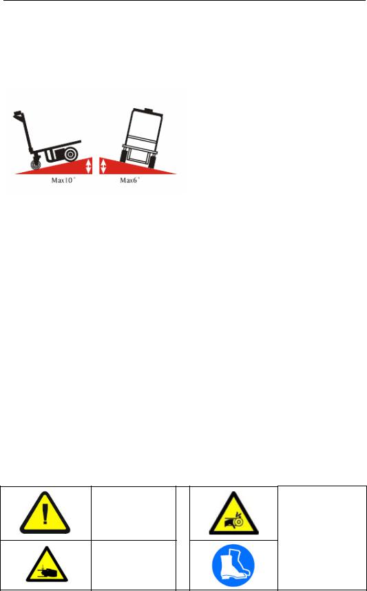
•When climbing an incline, try to keep your E-CART moving, if you must stop, start
7
E-CART (ELECTRIC CART)
up again slowly and then accelerate smoothly with caution. Avoid sudden stops, lean forward towards your handlebars to increase stability.
Warning: Any attempt to climb or descend an incline steeper than shown below may put your E-CART in an unstable position and cause it to tip, resulting in personal injury.
SYMBOLS & PICTURES
In addition to the text and illustrations, this operating manual contains various symbols which should draw attention to the safety requirements.
They generally have the following appearance:
Signal wording |
Explanation |
DANGER |
Warning of an imminent danger! |
|
Non-observance cause death or serious injury |
WARNING |
Warning of a possibly incoming dangerous situation. |
|
Non-observance may cause death or serious injury. |
CAUTION |
Warning of a possibly incoming dangerous situation. |
|
May also be used for warnings of major damage to property. |
Other definitions: |
|
|
|
DIRECTION |
Marks recommendations for use and other useful information. |
|
Does not warn of dangerous situations. |
IMPORTANT |
Warns of a harmful situation. |
|
Non-observance may cause damage to material. |
USE SYMBOLS & PICTURES
Possible danger to file |
Do not reach into |
and limb or machine! |
running motor! |
Danger of crushing! |
Wear safety shoes |
8

E-CART (ELECTRIC CART)
Product description
Designated use
The CART is to be used on hard level surfaces.
To move the stacker between buildings, warehouses etc
The gradient of the slope must not be more than 5%
Make sure load is not loose or unstable.
Do not pick up loads on tips or forks or edge of platform.
Do not overload.
The road surfacing must be solid and have a good grip.
Travel routes must offer sufficient load-bearing capacity for the loaded CART.
The CART is not suitable for continuous use in cool-houses!
Ambient conditions |
|
|
|||
|
|
|
|
°F |
|
Temperature |
|
From |
14 |
||
|
|
|
To |
113 |
°F |
Degree of humidity |
|
≤70 |
% |
||
|
|
|
|
|
|
Permitted |
floor |
|
|
|
|
incline |
|
|
|
|
|
y |
Loaded |
|
|
Max. 0.5 |
% |
y |
Unloaded ¹ |
|
|
Max. 2.0 |
% |
OPERATION
Visually inspect E-CART for damaged and worn parts, before Electric Cart is taken into operation. Authorized person should read and understand all instructions
Caution!
Pedestrian controlled industrial trucks may only be operated by persons who have been satisfactorily instructed in operating the truck and have proved their ability to operate the truck to the responsible representative of the operating
company.
The first driving attempts should take place on level and spacious surfaces.
Recommendation:
The operator who is to maneuver the CART should be allowed to practice, when unloaded, until they can safely operate these functions.
9

E-CART (ELECTRIC CART)
Travel
The butterfly switch controls the direction and speed of the lift truck. Rotating the butterfly control towards the forks moves the truck in the forward direction. Rotating the butterfly control away from the forks, moves the truck in the reverse direction. The control is progressive – the further you rotate the control, the faster the truck will travel.
DIRECTIONAL SPEED CONTROL THROTTLE
Emergency reverse safety button
At the top of the handle is a red safety reverse button. The button is designed to change the travel direction away from the operator when depressed. The truck will stop moving away from the operator when the button is released. When the fork truck is traveling forward (away from the operator) the button has no effect when activated.
If the belly switch becomes jammed or stuck, it will move forward (away from the operator) for a maximum of 3 seconds at which time the control circuit will become disabled until the handle is re-set to the full up or full down position and the belly switch is returned to normal operation.
BELLY SWITCH (SAFETY REVERSE BUTTON)
10
E-CART (ELECTRIC CART)
TO BRAKE
This cart is equipped with a brake that is applied between 1~5 degrees of the vertical position . When you release your hand from the handle. It will resume the neutral position automatically, as the brake in work. Always make sure that the brake is in work before operating the cart .
HORN
A horn is located on the front side of the handle.
HORN
11

E-CART (ELECTRIC CART)
Maintenance and repair
TROUBLESHOOTING GUIDE -- ______
Warning: Before performing any task, always block drive wheel off of the ground.
Consult the factory for problems at time of installation, or for any problems not addressed below.
Problem: |
Possible cause(s): |
Action: |
|
|
|
|
|
Unit doesn’t move when controls are |
Battery voltage low (<17) |
Charge batteries. |
|
used. |
Problem with motor controller |
Consult diagnostics |
|
|
|
||
|
(check for LED flash code on side |
page/factory |
|
|
of controller) |
|
|
|
Fuse blown |
Remove back shroud and check |
|
|
|
fuses (3 fuses). |
|
|
|
|
|
Unit will not charge |
Charger malfunction |
Verify output voltage on charger, |
|
|
|
will only get a reading when |
|
|
|
connected to batteries; should be |
|
|
|
approximately 28 volts. |
|
|
Bad batteries |
Load test batteries |
|
|
|
|
|
Unit will not go forward; reverse |
Broken wire, or loose connection |
Locate Pin 2 on Molex connector at |
|
works; belly switch just kills unit |
|
motor controller. Trace wiring to |
|
(does not go forward and time out) |
|
contactor and verify connection. |
|
|
Contactor bad, motor controller bad |
When forward is depressed, there |
|
|
|
should be 24 volts on this wire |
|
|
|
from Molex connector to the |
|
|
|
contactor, if not, the motor |
|
|
|
controller may be bad; consult |
|
|
|
diagnostics page/factory. |
If 24 |
|
|
volts is present at contactor, |
|
|
|
verify ground connection. |
If |
|
|
ground is good, remove both wires |
|
|
|
and check with ohm meter; |
|
|
|
resistance should be |
|
|
|
approximately 38 ohms. If it’s |
|
|
|
open or zero, the contactor should |
|
|
|
be replaced. |
|
|
|
|
|
Unit will not go reverse; belly switch |
Broken wire, or loose connection, |
Same as above; except locate Pin 3 |
|
works (i.e. when the handle is in |
contactor bad, motor controller |
on Molex connector on motor |
|
operating range and rotating |
bad |
controller…and follow procedure. |
|
throttle in reverse and the belly |
|
|
|
switch is hit, the unit moves |
|
|
|
forward and times out) |
|
|
|
|
|
|
|
12

E-CART (ELECTRIC CART)
Problem: |
Possible cause(s): |
Action: |
|
|
|
|
|
Unit will not go forward, or reverse, |
Broken wire, or loose connection, |
Locate Pin 6 on Molex connector at |
|
but belly switch still functions |
bad motor controller, |
the motor controller. |
Try to drive |
properly. |
|
the unit in forward, there should |
|
|
|
be 0 to 5 volts (5v is full throttle) |
|
|
|
at this pin. If there is voltage and |
|
|
|
the unit does not move, the motor |
|
|
|
controller may be bad, consult |
|
|
|
diagnostics page/factory. If |
|
|
|
there is no voltage, trace the |
|
|
|
wiring back towards the tiller head |
|
|
|
and check voltage on each side of |
|
|
|
connectors. Continue this until |
|
|
|
bad connection is found. |
|
|
Throttle assembly bad |
If the connections are all good, and |
|
|
|
there is no voltage coming out of |
|
|
|
throttle assembly, then the |
|
|
|
throttle assembly may be bad. |
|
|
|
Verify there is 24 volts going into |
|
|
|
the assembly and that there is a |
|
|
|
good ground. If there is still no |
|
|
|
output voltage for pin 6, replace |
|
|
|
throttle assembly. See Fig. 1 |
|
|
|
|
|
Unit will not move forward, or |
Blown fuse |
Verify fuses are good, replace if |
|
reverse, and the Belly switch will |
|
blown. |
|
not function, unit does turn on as |
|
|
|
indicated by the battery gage |
Broken wire, or loose connection |
Locate Pin 7 on Molex connector at |
|
lighting up. |
|
the motor controller. |
Trace wire |
|
|
back up to tiller head and verify |
|
|
|
continuity all the way to the |
|
|
|
throttle assembly. Repair any |
|
|
|
loose connections. |
|
|
|
If there is continuity up to the |
|
|
|
throttle assembly, then check the |
|
|
|
ground wire that comes off of B- |
|
|
|
on the motor controller (3rd |
|
|
|
terminal down). Add more length |
|
|
|
to this wire if necessary, and |
|
|
|
re-terminate with a ring terminal. |
|
|
|
|
|
13
 Loading...