


VESTIL MANUFACTURING CORP.
2999 North Wayne Street, P.O. Box 507, Angola, IN 46703 Telephone: (260) 665-7586 -or- Toll Free (800) 348-0868 Fax: (260) 665-1339
www.vestilmfg.com e-mail: sales@vestil.com
HYDRA SERIES MANUAL HYDRAULIC LIFT TRUCKS
ASSEMBLY, USE, AND MAINTENANCE MANUAL
RECEIVING INSTRUCTIONS:
After delivery, IMMEDIATELY remove the packaging from the product in a manner that preserves the packaging and maintains the orientation of the product in the packaging; then inspect the product closely to determine whether it sustained damage during transport. If damage is discovered during the inspection, immediately record a complete description of the damage on the bill of lading. If the product is undamaged, discard the packaging.
NOTES:
1)Compliance with laws, regulations, codes, and non-voluntary standards enforced in the location where the product is used is exclusively the responsibility of the owner/end-user
2)VESTIL is not liable for any injury or property damage that occurs as a consequence of failing to apply either:
a) Instructions in this manual; or b) information provided on labels affixed to the product. Neither is Vestil responsible for any consequential damages sustained as a result of failing to exercise sound judgment while assembling, installing, using or maintaining this product.
Table of Contents
Product Specifications…………………………………..………………………………………………………………………………………. 2 Signal Words….………………………………………………………………………………………………………………………………….. 3 Safety Recommendations………………………………………………………………..…...………………………………………………… 3 FIG. 1: HYDRA-2 exploded parts diagram & bill of materials………………………………………………………………………………..4 FIG. 2: HYDRA-4 exploded parts diagram & bill of materials………………………………………………………………………………..5 FIG. 3: HYDRA-HD exploded parts diagram & bill of materials…………………………………………………………………………….. 6 Function tests before use……………………………………………………………………………………………………………………….. 7 Operation instructions…………………………………………………………………………………………………………………………… 7 - 8 Inspections & Maintenance……………………………………………………………………………………………………………………... 9 Troubleshooting Guide………………………………………………………………………………………………………………………….. 10 Detailed Troubleshooting—Foot Pump………………………………………………………………………………………………………... 11-15 FIG. 4: Hydraulic System Diagram…………………………………………………………………………………………………………….. 15 Detailed explanation of Hydraulic System Operation…………………………………………………………………………………………16 Label Placement Diagram……...………………………………………………………………………………………………………………..17 Limited Warranty…...……………………………………………………………………………………………………………………………. 18
Copyright 2015 Vestil Manufacturing Co. |
Page 1 of 18 |
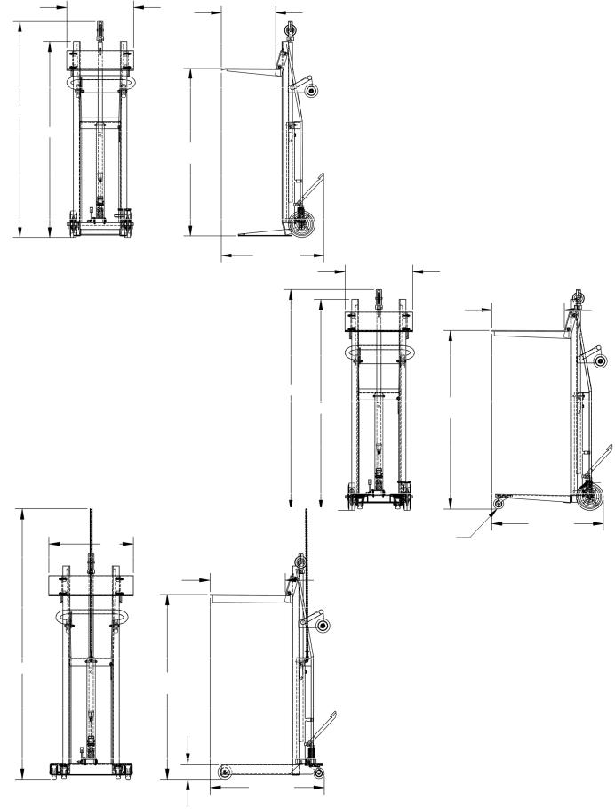
Product specifications:
Dimensions and other product specifications appear in the following table based on the following diagrams.
20” 161/4”
|
|
|
|
|
|
HYDRA-2 |
|
|
|
|
|
|
|
|
|
|
Deck operated by foot pump |
|
|
|
|
|
|
|
|
|
|
Capacity: |
750 lb. |
|
|
|
13 |
|
|
|
|
|
|
|
|
||
64 /16” |
|
|
|
|
Overall width: |
20 inches |
|
|
|
|
|
|
|
|
|
|
|
|
|
||
|
|
|
|
|
|
Overall length: |
3011/16 inches |
|
|
|
13 |
|
|
|
|
|
|
||||
|
58 /16” |
|
|
|
Overall height: |
6413/16 inches |
|
|
|
|
|
|
0” to 48” |
1 |
/4 |
inches |
|||||
|
|
|
||||||||
|
|
|
|
service |
|
Deck dimensions: |
20 inches x 16 |
|
||
|
|
|
|
|
Service range: |
0 inches to 48 inches |
||||
|
|
|
|
range |
|
|||||
|
|
|
|
|
|
|
|
|
|
|
3011/16”
20”
213/8”
HYDRA-4 |
|
|
|
|
|
|
|
|
|
|
|
Deck operated by foot pump |
|
|
|
|
|
|
|
|
|
||
Capacity: |
750 lb. |
|
|
|
|
|
|
|
|
|
|
Overall width: |
20 inches |
|
|
|
|
|
|
|
|
|
|
|
|
|
13 |
|
|
|
|
||||
|
|
|
|
|
|
3 |
|||||
|
15 |
|
|
|
|
|
64 /16” |
|
|
4 /4” to |
|
Overall length: |
3213/16 |
inches |
|
|
|
|
|
|
|
|
523/4” |
|
|
|
|
|
|||||||
|
|
|
7 |
||||||||
Overall height: |
64 /16 |
inches |
3 |
/8 |
inches |
|
|
61 /16” |
|
service |
|
Deck dimensions: |
20 inches x 21 |
|
|
|
|
||||||
|
|
|
|
|
|
|
|||||
Service range: |
4 inches to 523/4 inches |
|
|
|
|
|
|
||||
|
|
|
|
|
|
|
|
|
|
|
|
3215/16” |
|
|
20” |
|
|
|
3” x 11/4” hard rubber |
|
|
|
|
||||
|
|
|
|
|
|
|
|
|
|||||
|
|
|
|
swivel caster |
|
|
|
|
|
|
|||
|
|
|
|
|
|
|
|
|
|
|
|
|
|
|
|
|
|
|
|
|
|
|
|
|
|
|
|
|
|
|
|
|
|
|
|
|
|
|
|
||
|
|
|
|
213/8” |
|
|
|
|
|
|
|||
|
|
|
|
|
|
HYDRA-HD |
|
|
|
|
|
|
|
|
|
|
|
|
|
Deck operated by foot pump |
|
|
|
|
|||
|
|
|
|
|
|
Capacity: |
1,000 lb. |
|
|
|
|
||
|
|
|
|
|
|
Overall width: |
24 inches |
|
|
|
|
||
|
|
|
|
|
|
Overall length: |
327/16 inches |
|
|
|
|
||
1 |
|
|
|
|
|
|
|
|
|
||||
77 /4” |
|
3 |
|
|
|
|
|
1 |
|
|
|
|
|
|
|
4 /4” to |
|
|
|
|
|
|
|
|
|
||
|
|
523/4” |
|
|
|
Overall height: |
77 /4 inches |
|
|
|
|
||
|
|
|
|
|
Deck dimensions: |
24 inches x 213/8 |
inches |
||||||
|
|
service |
|
|
|
|
|
3 |
3 |
|
|||
|
|
|
|
|
|
Service range: |
4 /4 inches to 52 |
|
|
/4 inches |
|||
|
|
|
|
|
|
|
|
||||||
43/8”
327/16”
Copyright 2015 Vestil Manufacturing Co. |
Page 2 of 18 |

Signal Words:
This manual uses SIGNAL WORDS to indicate the likelihood of personal injuries, as well as the probable seriousness of those injuries, if the product is misused in the ways described. Other signal words call attention to uses of the product likely cause property damage. The signal words used appear below along with the meaning of each word:
Identifies a hazardous situation which, if not avoided, WILL result in DEATH or SERIOUS INJURY. Use of this signal word is limited to the most extreme situations.
Identifies a hazardous situation which, if not avoided, COULD result in DEATH or SERIOUS INJURY.
Indicates a hazardous situation which, if not avoided, COULD result in MINOR or MODERATE injury.
Identifies practices likely to result in product/property damage, such as operation that might damage the product.
Each person who assembles, installs, uses, or maintains this product should read the entire manual in advance and fully understand the directions. If after reading the manual you do not understand an instruction, ask your supervisor or employer for clarification, because failure to adhere to the directions in this manual might result in serious personal injury.
Safety Recommendations:
We strive to identify foreseeable hazards associated with the use of our products. However, material handling is dangerous and no manual can address every risk. The end-user ultimately is responsible for exercising sound judgment at all times.
 Improper or careless operation might result in serious personal injuries sustained by the operator and bystanders. Always apply material handling techniques learned during training and use the product properly.
Failure to read and understand the entire manual before assembling, using or servicing the product constitutes misuse. Read the manual to refresh your understanding of proper use and maintenance procedures as necessary.
Prior to each use, ALWAYS inspect the area where you intend to use the lifter. Inspect the area for unusual conditions that might require special precautions. See “Warning” messages on p. 7.
DO NOT use a malfunctioning lifter; always perform the “Functions Checks/Tests” described on p. 7 before each use.
Regardless of whether the lifter is loaded or unloaded, DO NOT stand or travel under the deck and DO NOT allow any other person to stand or travel under the deck.
Inform all persons in the area that you are going to use the lifter. Instruct them to stay clear of the device and the supported load during operation.
ALWAYS make sure that your clothing and body do not contact the moving parts during operation. In particular, avoid contact with the chain assembly (Item #21, Fig. 1; Item #22, Fig. 2; and Item #17, Fig. 3) and with the roller bearings. ONLY control the lifter from the “Operator Position,” shown in the figures that appear on p. 8. DO NOT move the lifter or raise or lower the forks unless you are in the operator position.
DO NOT allow people to ride on the lifter.
ALWAYS load the HYDRA-Lift according to the list of 5 recommendations that appears below. Failure to properly position a load on the deck might cause the lifter to tip over and you could be injured as a consequence.
1.DO NOT exceed the maximum rated load (capacity). The rated load of your lifter is posted on a label (see Fig. 5 on p. 18).
2.ONLY move loads using the deck platform or the optional forks.
3.ALWAYS properly center the load. DO NOT handle off-center loads or loads that cannot be centered.
4.Start and stop gradually to avoid upsetting the load on the deck.
5.NEVER tilt the lifter while carrying a load. All four castors must maintain contact with the ground when a load is on the deck (or forks).
NOTE: The HYDRA-2 model has only 2 wheels and thus operates like a dolly: it must be tilted towards the operator in order to drive it from one location to another. After loading the deck of a Hydra-2, verify that you will be able to control the loaded lifter, by tilting it into the drivable position. If the weight is too much for you to safely control, DO NOT use the Hydra-2 to transport the load.
DO NOT transport loads up or down stairs.
Copyright 2015 Vestil Manufacturing Co. |
Page 3 of 18 |

Fig. 1: HYDRA-2 exploded parts diagram & bill of materials
|
Item No. |
Part No. |
Description |
Quantity |
|
|
1 |
33-514-092 |
Frame Weldment |
1 |
|
|
2 |
33-513-044 |
Deck Plate Weldment |
1 |
|
|
3 |
16-132-009 |
HR–4/1.25–SLB-S |
2 |
|
|
4 |
11113 |
3/8”-16 x 21/2” Zinc-plated HHCS Bolt |
2 |
|
|
5 |
37024 |
3/8”-16 nylock nut |
6 |
|
|
6 |
16-132-200 |
8” x 2” red hard rubber wheel (red) |
2 |
|
|
7 |
65107 |
5/32” x 2” zinc-plated cotter pin |
2 |
|
|
8 |
33-027-003 |
Cam roller, bearing, deck |
4 |
|
|
9 |
33008 |
3/8” USS Zinc-Plated Flat Washer |
8 |
|
|
10 |
11111 |
3/8” - 16 x 2” Zinc-Plated Bolt HHCS |
4 |
|
|
11 |
33-542-001 |
Assembly, pulley |
1 |
|
|
12 |
21-537-002 |
Weldment, wheel brake assembly |
1 |
|
|
13 |
21-037-015 |
Brake lever, formed |
1 |
|
|
14 |
01-640-031 |
Pump, manual, 24in. stroke |
1 |
|
|
15 |
11010 |
1/4” - 20 x 13/4” HHCS zinc-plated #2 bolt |
2 |
|
|
16 |
42034 |
5/16” – 18UNC x 21/2” U-bolt |
1 |
|
|
17 |
33620 |
5/16” zinc-plated lock washer |
2 |
|
|
18 |
36104 |
5/16” – 18 zinc-plated hex nut |
2 |
|
|
19 |
33-542-002 |
Chain assembly (#50), hydrapulley |
1 |
|
|
20 |
33018 |
3/4” USS zinc—plated flat washer |
2 |
|
|
21 |
36102 |
1/4” – 20 zinc-plated hex nut |
2 |
|
Copyright 2015 Vestil Manufacturing Co. |
Page 4 of 18 |
||||
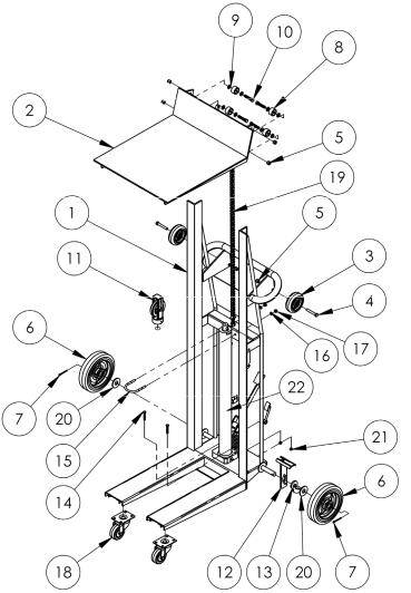
Fig. 2: HYDRA-4 exploded parts diagram & bill of materials
|
Item No. |
Part No. |
Description |
Quantity |
|
|
1 |
33-514-093 |
Frame Weldment |
1 |
|
|
2 |
33-513-043 |
Deck Plate Weldment |
1 |
|
|
3 |
16-132-009 |
HR–4/1.25–SLB-S |
2 |
|
|
4 |
11113 |
3/8”-16 x 21/2” Zinc-plated HHCS Bolt |
2 |
|
|
5 |
37024 |
3/8”-16 nylock nut |
6 |
|
|
6 |
16-132-200 |
8” x 2” red hard rubber wheel (red) |
2 |
|
|
7 |
65107 |
5/32” x 2” zinc-plated cotter pin |
2 |
|
|
8 |
33-027-003 |
Cam roller, bearing, deck |
4 |
|
|
9 |
33008 |
3/8” USS Zinc-Plated Flat Washer |
8 |
|
|
10 |
11111 |
3/8” - 16 x 2” Zinc-Plated Bolt HHCS |
4 |
|
|
11 |
33-542-001 |
Assembly, pulley |
1 |
|
|
12 |
21-537-002 |
Weldment, wheel brake assembly |
1 |
|
|
13 |
21-037-015 |
Brake lever, formed |
1 |
|
|
14 |
11010 |
1/4” - 20 x 13/4” HHCS zinc-plated #2 bolt |
2 |
|
|
15 |
42034 |
5/16” – 18UNC x 21/2” U-bolt |
1 |
|
|
16 |
33620 |
5/16” zinc-plated lock washer |
2 |
|
|
17 |
36104 |
5/16” – 18 zinc-plated hex nut |
2 |
|
|
18 |
16-132-201 |
Caster, PP-3/1.25 swivel (red) |
2 |
|
|
19 |
33-542-003 |
Chain assembly (#50), hydrapulley |
1 |
|
|
20 |
33018 |
3/4” USS zinc—plated flat washer |
4 |
|
|
21 |
36102 |
1/4” – 20 zinc-plated hex nut |
2 |
|
|
22 |
01-640-031 |
Pump, manual, 24in. stroke |
1 |
|
Copyright 2015 Vestil Manufacturing Co. |
Page 5 of 18 |
||||

Fig. 3: HYDRA-HD exploded parts diagram & bill of materials
|
Item No. |
Part No. |
Description |
Quantity |
|
|
1 |
33-514-094 |
Frame Weldment |
1 |
|
|
2 |
33-513-045 |
Deck Plate Weldment |
1 |
|
|
3 |
16-132-009 |
HR–4/1.25–SLB-S |
4 |
|
|
4 |
11113 |
3/8”-16 x 21/2” Zinc-plated HHCS Bolt |
4 |
|
|
5 |
37024 |
3/8”-16 nylock nut |
8 |
|
|
6 |
33-027-003 |
Cam roller, bearing, deck |
4 |
|
|
7 |
11111 |
3/8” - 16 x 2” Zinc-Plated Bolt HHCS |
4 |
|
|
8 |
33008 |
3/8” USS Zinc-Plated Flat Washer |
8 |
|
|
9 |
16-132-327 |
Caster, PU-3/1.5-S swivel (red) |
2 |
|
|
10 |
33-542-001 |
Assembly, pulley |
1 |
|
|
11 |
11010 |
1/4” - 20 x 13/4” HHCS zinc-plated #2 bolt |
2 |
|
|
12 |
42034 |
5/16” – 18UNC x 21/2” U-bolt |
1 |
|
|
13 |
33620 |
5/16” zinc-plated lock washer |
2 |
|
|
14 |
36104 |
5/16” – 18 zinc-plated hex nut |
2 |
|
|
15 |
33-542-003 |
Chain assembly (#50) |
1 |
|
|
16 |
36102 |
1/4” – 20 zinc-plated hex nut |
2 |
|
|
17 |
01-640-043 |
Pump, manual, 24in. stroke |
1 |
|
Copyright 2015 Vestil Manufacturing Co. |
Page 6 of 18 |
||||
 Loading...