


OPERATION & SERVICE MANUAL
S SERIES STACKER WITH POWERED DRIVE & POWER LIFT
Vestil Manufacturing Corp.
2999 North Wayne St., Angola, IN 46703
Ph: 260-665-7586 . Fax: 260-665-1339 E-mail: Sales@vestil.com
Website: www.vestil.com
1

General
Read and follow the instructions contained in this operating manual without fail!
Only trained, well-informed personnel, who have been instructed in accordance with this operation manual, may use or work on the machine.
Liability or guarantee is waived if:
The instructions in this operating manual are not observed.
The high-lift stacking truck is operated, cleaned or maintained incorrectly.
Alterations to the functions are carried out without the consent of manufacturer.
Original spare parts are not used.
Safety instructions
This chapter informs the user about residual dangers relating to the correct use of the products. It contains generally valid safety instructions which must be observed.
Safety instructions relating to specific actions or situations are listed prior to the respective action and/or description of the situation in the chapter.
Principles
This product complies with state-of-the –art technical standards and recognized safety regulations, but there are still dangers which may occur which must be considered.
Only operate the product in a perfect condition and observing the information contained in the operating manual.
The operator is responsible for integrating the product with as little risk as possible into his working environment. This obligation continues through every phase of the products lifespan, beginning at the planning stage. Residual dangers are to be minimized.
Only trained, competent personnel who have been instructed using the operating manual and the product are permitted to work with the truck.
The operating manual must be understood (responsibility, checking)
Declaration:
I have read this manual and, in particular, have taken note of the caution.
Name |
Date |
Signature |
|
|
|
|
|
|
|
|
|
2

Specification
SPECIFICATION
|
|
|
S-62-FF |
S-62-AA |
S-62-FA |
|
Capacity |
|
2000 lbs. |
2000 lbs. |
2000 lbs. |
|
Fork Lift Height |
62" |
62" |
62" |
|
|
Fork Dimension |
42x5.9x2 3/8" |
42x4x1-1/4"" |
42x5.9x2 3/8" |
|
|
Overall fork width |
26-3/4" |
26-3/4" |
26-3/4" |
|
|
Ground Clearance |
1" |
1" |
1" |
|
|
Lowered Fork H. |
3-3/8" |
2-1/8" |
2-9/16" |
|
|
H. Overall Extended |
81-7/8" |
81-7/8" |
81-7/8" |
|
|
Head Dimension |
26-1/2x30x29-3/4" |
26-1/2x30x29-3/4" |
26-1/2x30x29-3/4" |
|
|
Loading Center |
23-5/8" |
23-5/8" |
23-5/8" |
|
|
Wheel Base |
|
44-3/4" |
44-3/4" |
44-3/4" |
|
Turning Radius |
55" |
55" |
55" |
|
|
Support Wheel |
Φ4x2" |
Φ4x2" |
Φ4x2" |
|
|
Front Wheel |
|
Φ3-1/8x3-3/8" |
Φ3-1/8x3-3/8" |
Φ3-1/8x3-3/8" |
|
Drive Wheel |
|
Φ10x3-1/8" |
Φ10x3-1/8" |
Φ10x3-1/8" |
|
Overall Size |
|
68x30x82 |
69x46x82 |
68x46x82 |
|
Lift |
Load |
2.95"/s |
2.95"/s |
2.95"/s |
|
Speed |
Unload |
5.9"/s |
5.9"/s |
5.9"/s |
|
Lower |
Load |
4"/s |
4"/s |
4"/s |
|
|
|
|
|
|
|
Speed |
Unload |
2"/s |
2"/s |
2"/s |
|
Travel |
Load |
5km/h |
5km/h |
5km/h |
|
Speed |
Unload |
6km/h |
6km/h |
6km/h |
|
Drive Motor |
|
24V/700W |
24V/700W |
24V/700W |
|
Lift Motor |
|
24V/2.0KW |
24V/2.0KW |
24V/2.0KW |
|
Controller |
|
1207A-4102 |
1207A-4102 |
1207A-4102 |
|
Battery |
|
2x12V/70Ah |
2x12V/70Ah |
2x12V/70Ah |
|
Battery Charger |
DC 24V/6A Soneil |
DC 24V/6A Soneil |
DC 24V/6A Soneil |
|
|
Weight |
|
950 lbs. |
990 lbs. |
970 lbs. |
|
Load Grade ability |
6% |
6% |
6% |
|
|
Unload Grade ability |
10% |
10% |
10% |
|
|
Width of Aisle |
35-1/2" |
52" |
52" |
|
Note: The load capacity is based on the situation when the center of the gravity is located at the center of length of forks. When the center of gravity of goods is out of the center of forks, the load capacity will be lessened compared to the center.
3
CONTENTS
General ………………………………………………………………………………… |
2 |
Specification …………………………………………………… |
3 |
Receiving instructions ……………………………………………………………… |
5 |
Safety Notes ……….…………………………………………………………………… |
6 |
Product description ………………………………………………………………… |
7 |
Designated use …. … …... … …………………………………………………… |
7 |
Signs on the Truck ……………………………………………………………….. |
8 |
Transport ………………………………………………………………………………… |
9 |
Operation ……………………………………………………………………………… |
10 |
Operation ……………………………………………………………………………… |
11 |
Operating elements ……………………………………………………………… |
|
Safety elements ………………………………………………………………… |
12 |
Driving, braking and horn………………………………………………………… |
13 |
Lifting and lowering ………… …………………………………………………… |
14 |
Traveling ………………………………………………………………………….. |
15 |
Taking up the load………………………………………………………………… |
16 |
Driving on sloping surfaces……………………………………………………… |
17 |
Maintenance and repair …………………………………………………………… |
18 |
Trouble shooting ………………………………………………………………… |
18-22 |
Changing batteries ……………………………………………………………… |
23-24 |
Changing motor controller …………………………………………………….. |
25-31 |
Belly switch trouble shoot ……………………………………………………… |
32-49 |
Maintenance daily/before use, monthly, annually …………….…………….. |
50 |
Maintenance and care of the load chains …………………………………… |
51 |
Chain inspections ………………………………………………………………… |
52 |
Temporary lay-up ………………………………………………………………… |
53 |
Parts List ………………………………………………………………………………… |
54-60 |
4
Receiving Instructions
Every unit is thoroughly tested and inspected prior to shipment. However, it is possible that the unit may incur damage during transit. If you see damage when unloading, make a note of it on the SHIPPER RECEIVER.
Remove all packing & strapping material, inspect for damage. IF DAMGE IS EVIDENT, FILE A CLAIM WITH THE CARRIERIMMEDIATELY! Also, check fork size, type of power unit, etc., to see that the unit is correct for the intended application.
Warnings & Safety Instructions
Insure that all employees understand and follow the following instructions
∙Read and understand the owner’s manual before using or servicing the stacker.
∙Do not use the stacker if any damage or unusual noise is observed.
∙Improper use of this lift truck could result in injury and damage to load or equipment.
∙Always watch the stacker and any load on it carefully when it is being used or moved.
∙Avoid sudden stops or quick turns to turns to prevent accidental tipping of the load.
∙Load must be centered and evenly distributed on the forks.
∙Park the truck on level surfaces and not in the way of other products
∙When parked, lower the load fork completely.
∙When parked, push E-switch push-button down.
∙Do not perform any modifications to the stacker without the manufacturer’s approval. Failure to receive authorization for changes to the equipment could void the warranty.
∙Do not use brake fluid or jack oil in the hydraulic system. If oil is needed, use an anti-wear hydraulic oil with a viscosity grade of 150 SUS at 100°F, (ISO 32 @ 40°C), or a non-synthetic transmission fluid.
∙Use only replacement parts either supplied or approved by the manufacturer.
5
Safety notes
Symbols and pictograms used
In addition to the text and illustrations, this operating manual contains various symbols which should draw attention to the safety requirements.
They generally have the following appearance:
Signal wording |
Explanation |
DANGER |
Warning of an imminent danger! |
|
Non-observance cause death or serious injury |
WARNING |
Warning of a possibly incoming dangerous situation. |
|
Non-observance may cause death or serious injury. |
CAUTION |
Warning of a possibly incoming dangerous situation. |
|
May also be used for warnings of major damage to property. |
Other definitions: |
|
|
|
DIRECTION |
Marks recommendations for use and other useful information. |
|
Does not warn of dangerous situations. |
IMPORTANT |
Warns of a harmful situation. |
|
Non-observance may cause damage to material. |
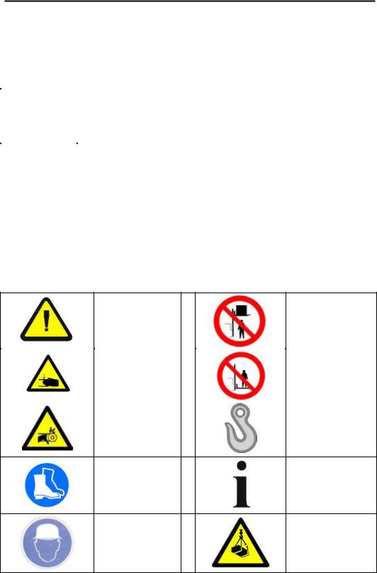
Used symbols and pictograms
Possible |
danger |
to |
|
Do not step onto when |
|
file |
and |
limb |
or |
|
|
|
load is raised! |
||||
machine! |
|
|
|
||
|
|
|
|
||
|
|
|
|
|
|
Danger of crushing! |
|
It is forbidden to ride |
|||
|
on the truck! |
||||
|
|
|
|
|
|
|
|
|
|
|
|
Do |
not |
reach |
into |
|
Suspension points for |
running motor! |
|
|
transport of truck! |
||
Wear safety shoes |
Important |
Wear helmet |
Suspended |
load |
warning! |
|
|
|
|
6
Product description
Designated use
The stacker is designated for lifting, lowering and transportation of loads according to the specifications of the identification plate.
The stacker is to be used on hard level surfaces.
To move the stacker between buildings, warehouses etc
The gradient of the slope must not be more than 10%
Make sure load is not loose or unstable.
Do not pick up loads on tips or forks or edge of platform.
Do not overload.
The road surfacing must be solid and have a good grip.
Travel routes must offer sufficient load-bearing capacity for the loaded truck.
The stacker is not suitable for continuous use in cool-houses!
Ambient conditions
Temperature |
|
From |
14 |
°F |
|
|
|
|
To |
113 |
°F |
Degree of humidity |
|
≤70 |
% |
||
|
|
|
|
|
|
Permitted |
floor |
|
|
|
|
incline |
|
|
|
|
|
|
Loaded |
|
|
Max. 0.5 |
% |
|
Unloaded ¹ |
|
|
Max. 2.0 |
% |
Dimensions and weights |
|
|
|||
|
|
|
|
||
Mass (dead weight) |
m |
480/750 |
kg |
||
|
|
|
|
|
|
WARNING!
The user is responsible for determining the actual load bearing capacity of a high-lift stacking truck. This can depend on the user, the condition of both the floor and the high-lift stacking truck and the regularity of the maintenance intervals.
7

Product description
8
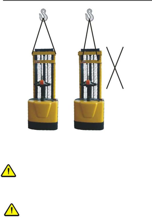
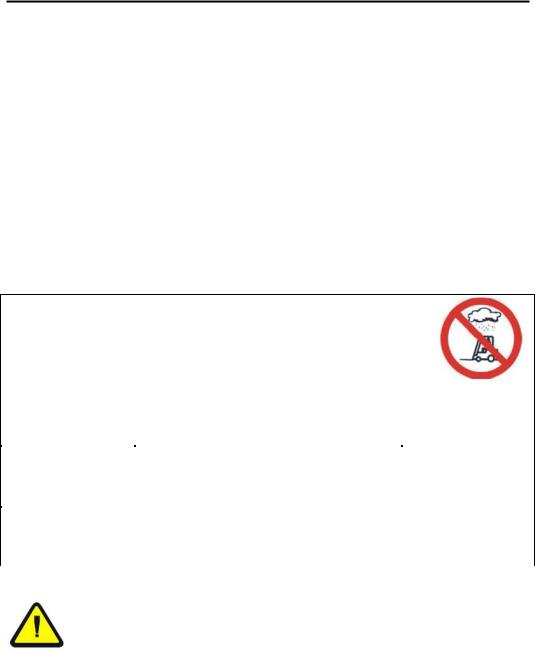
Removing from the pallet or lifting the product
Lifting belt specification— Use polyester lifting sling or nylon sling and hoist with a minimum of 2,000 lb. capacity.
CAREFUL
To pick up the unit only use overhead hoist, forklift or loading crane with sufficient carrying capacity!
Refer to the identification plate for the weight of the truck.
DANGER
When unloading the truck, all personnel should be cleared from area.
9

OPERATION
Visually inspect stacker for damaged and worn parts, before stacker is taken into operation. Authorized person should read and understand all instructions
The lifting truck is ready for immediate use once the packaging has been removed.
The battery is full and charged.
The hydraulic tank is full.
The driving gear is filled with oil filling for approx. 200 operation hours.
The steering roller and the running rollers are equipped with bearings which do not require maintenance; all mast rollers are also free from maintenance.
Caution!
Pedestrian controlled industrial trucks may only be operated by persons who have been satisfactorily instructed in operating the truck and have proved their ability to operate the truck to the responsible representative of the operating company.
The first driving attempts should take place on level and spacious surfaces.
Recommendation:
The operator who is to maneuver the truck and is to control the lifting mechanism should be allowed to practice, when unloaded, until they can safely operate these functions.
Only then should they undertake the loading, transporting and unloading of load.
10
Operation
11
Operation
12
Operation
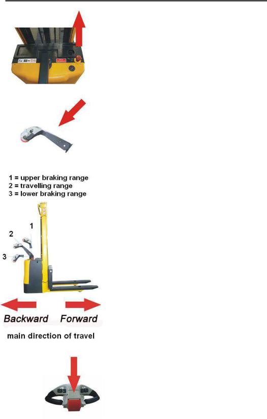
Driving
Pull up the red push button of the E-switch
Tilt the Control handle to driving position, the locking brake is released
If you release Control handle, this returns to the vertical start position, the truck brakes and the locking brake activates
The truck is steered via the Control handle
Brake:
This stacker is equipped with a magnetic brake that is applied between 10-15 degrees of the vertical position and between 85 -90 degrees of the lower position in the vertical operating of the handle. The brake can be operated at any point in the lateral operating of the handle. When you release your hand from the handle, it will resume neutral position automatically, and will activate the brake. Always make sure that the brake is in work before operating the stacker. When parked, always put the handle in the full vertical position with the brake applied and forks lowered.
Horn:
A horn is located on top of the handle.
13
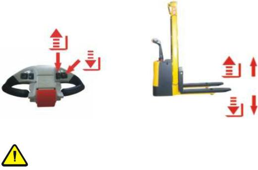
To raise and lower
The following are generally valid for the lifting and lowering procedure:
The red operating button of the EMERGENCY STOP pushbutton must be pulled upwards
Lifting and lowering movements are initiated by pressing the pushbuttons on the handle head.
There are four buttons located on the two sides of the handle. Each side of the control has one button for raising the forks and one button for lowering the forks. Always make sure when lifting that the load is within the capacity rating of your truck and that the load has been stacked safely on the pallet. Also, make sure that there is no one standing near the forks when raising or lowering. It is also important to make sure that the length of the forks corresponds to the opening in the bottom of the pallet. The load rollers must be placed between boards so when you raise the forks, the pallet will not be broken or damaged. Always make sure when entering the pallet that the forks are in the fully lowered position. Be careful when lifting pallets that are too short or too long for the truck
Warning
It is forbidden to climb or reach into any moving parts of the lifting truck-e.g. the lifting frame, thrust units, lifting mechanisms etc.
14
Travel
The butterfly switch controls the direction and speed of the lift truck. Rotating the butterfly control towards the forks moves the truck in the forward direction. Rotating the butterfly control away from the forks, moves the truck in the reverse direction. The control is progressive – the further you rotate the control, the faster the truck will travel.
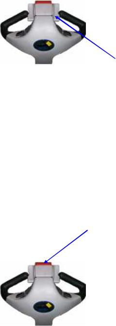
DIRECTIONAL SPEED CONTROL THROTTLE
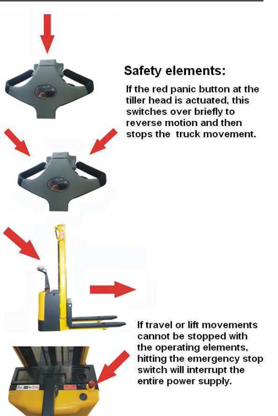
Emergency reverse safety button
At the top of the handle is a red safety reverse button. The button is designed to change the travel direction away from the operator when depressed. The truck will stop moving away from the operator when the button is released. When the fork truck is traveling forward (away from the operator) the button has no effect when activated.
If the belly switch becomes jammed or stuck, it will move forward (away from the operator) for a maximum of 3 seconds at which time the control circuit will become disabled until the handle is re-set to the full up or full down position and the belly switch is returned to normal operation.
BELLY SWITCH (SAFETY REVERSE BUTTON)
15
Operation
Lifting load
CAUTION!
Before lifting a load to be transported, ensure that the load does not exceed the carrying capacity of the truck.
The nominal carrying capacity and lifting heights can be viewed in the load diagram.
Ensure that the load can be taken up in a compact and stable manner. Slipping or falling of the load must be avoided.
The load must not project into the lifting frame.
The load must be centered and evenly distributed on the forks.
The load must not project more than 50mm over the end of the lifting forks.
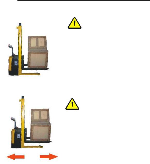
Transporting the load
CAUTION!
Raise the load only slightly to transport
For safety reasons (view) transport only in a forward direction
Only when lifting up or lowering down the load it is permissible to drive forwards or in reverse with a raised load
Lift up or lower down loads on level surfaces
When unloaded, move stacker only with forks lowered
16
Operation
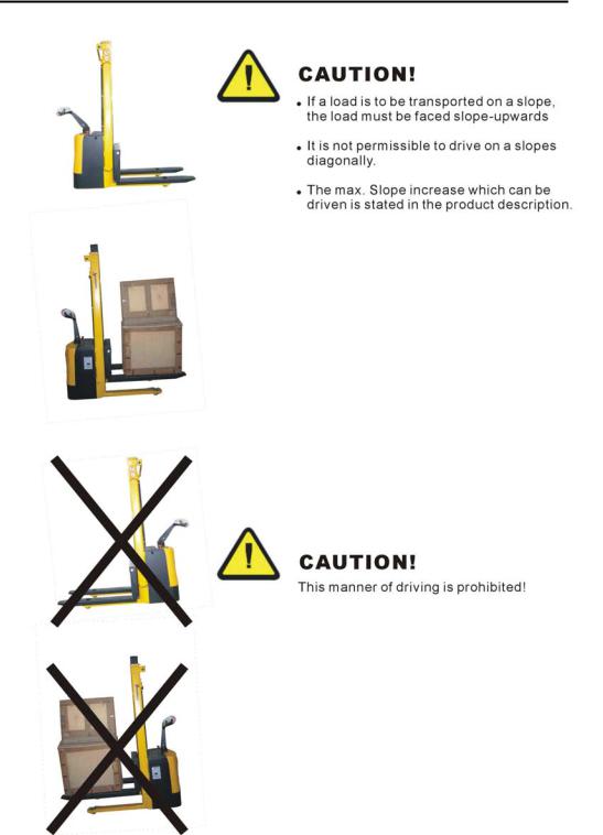
Driving on sloping surfaces
17
Maintenance and repair
TROUBLESHOOTING GUIDE -- ______
Warning: Before performing any task, always block drive wheel off of the ground.
Consult the factory for problems at time of installation, or for any problems not addressed below.
Problem: |
Possible cause(s): |
Action: |
Unit doesn’t move when controls are |
Battery voltage low (<17) |
used. |
|
|
Problem with motor controller |
|
(check for LED flash code on side |
|
of controller) |
|
Fuse blown |
Unit will not charge |
Charger malfunction |
Charge batteries.
Consult diagnostics page/factory
Remove back shroud and check fuses (3 fuses).
Verify output voltage on charger, will only get a reading when connected to batteries; should be approximately 28 volts.
|
Bad batteries |
Load test batteries |
|
Unit will not go forward; reverse |
Broken wire, or loose connection |
Locate Pin 2 on Molex connector at |
|
works; belly switch just kills unit |
|
motor controller. Trace wiring to |
|
(does not go forward and time out) |
|
contactor and verify connection. |
|
|
Contactor bad, motor controller bad |
When forward is depressed, there |
|
|
|
should be 24 volts on this wire |
|
|
|
from Molex connector to the |
|
|
|
contactor, if not, the motor |
|
|
|
controller may be bad; consult |
|
|
|
diagnostics page/factory. |
If 24 |
|
|
volts is present at contactor, |
|
|
|
verify ground connection. |
If |
ground is good, remove both wires and check with ohm meter; resistance should be approximately 38 ohms. If it’s open or zero, the contactor should be replaced.
Unit will not go reverse; belly switch works (i.e. when the handle is in operating range and rotating throttle in reverse and the belly switch is hit, the unit moves forward and times out)
Broken wire, or loose connection, contactor bad, motor controller bad
Same as above; except locate Pin 3 on Molex connector on motor controller…and follow procedure.
18
 Loading...