

Vertex Wireless VW450 User Manual
V.1.4E
1 | page

2 | page

1. INSTALLATION GUIDE
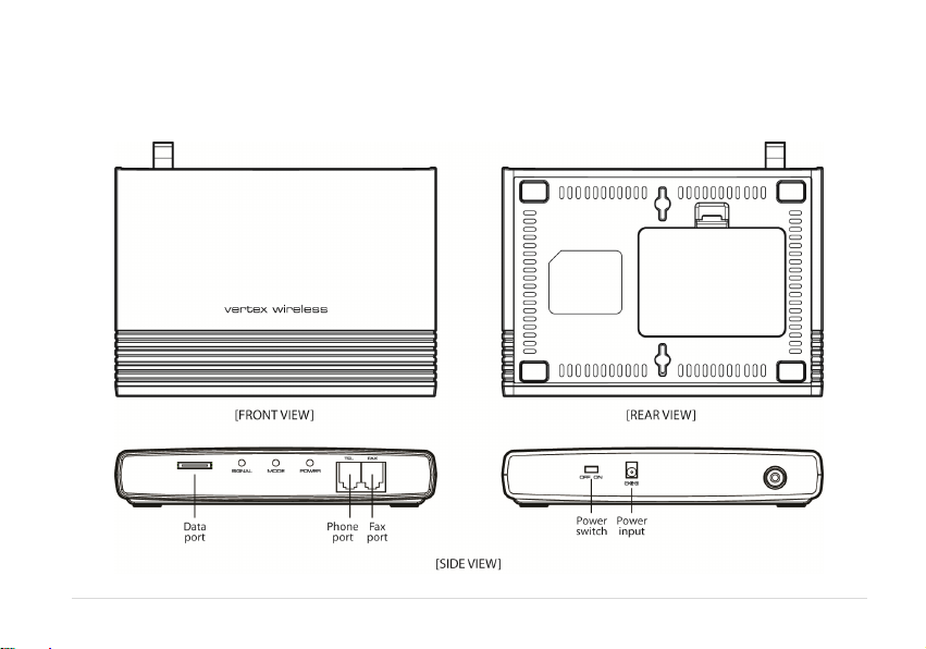
1.1. FRONT, SIDE AND REAR VIEW OF VW450
1.2. CHECKING THE COMPONENTS
1.3. SIM CARD INSTALLATION
1.4. BATTERY INSTALLATION
1.5. INSTALLATION OF THE ANTENNA AND LOCATION OF THE EQUIPMENT FOR VOICE SERVICE
1.6. DESKTOP INSTALLATION
1.7. WALL MOUNTING
2. GETTING TO KNOW VW450
2.1. LED STATUS INDICATOR
3. BASIC OPERATIONS
3.1. MAKING CALLS
3.2. RECEIVING CALLS
4. BASIC SETTINGS
4.1. RECEIVER VOLUME
4.2. DIAL DELAY TIME
4.3. SPEED DIAL ENTRY
4.4. TIME AND DATE
4.5. CID FORMAT
4.6. BAND SELECTION
4.7. EQUIPMENT LOCK
4.8. PIN LOCK
4.9. POLARITY REVERSE
4.10. LOOP CURRENT DISCONNECT
4.11. DTMF TONE GENERATION
3 | page
07
08
09
10
11
13
14
15
17
17
18
18
18
18
19
19
19
20
20
21
21

4.12. AUTOMATIC PIN ENTERING 21
4.13. FACTORY RESET
4.14. VOICEMAIL INDICATION
5. SUPPLEMENTARY SERVICE FEATURES
5.1. CALL FORWARDING
5.2. CALL BARRING
5.3. CALL WAITING
5.4. SIM SECURITY CODES
5.5. CALLER ID
6. DATA SERVICE FEATURES
7. FAX SERVICE FEATURE
7.1. ANALOG FAX
7.2. DIGITAL FAX
8. GENERAL INFORMATION
8.1. SPECIFICATIONS
8.2. ADDITIONAL SAFETY INFORMATION
8.3. GUARANTEE
8.4. TROUBLESHOOTING
9. CONFORMANCE STATEMENTS
APPENDIX A
4 | page
21
21
22
23
25
26
26
27
27
28
29
30
32
33
33

Welcome to your VW450
VW450 is a Fixed Wireless Terminal designed to provide better wireless connectivity between wire telephone and GSM
850/900/1800/1900 band network with high sensitivity to receive signal and large transmitting power to expand
extensively the effective coverage of GSM service.
Main function & features
- SIMPLE TO INSTALL AND EASY TO MAINTAIN
- COMPATIBLE TO MOST TELEPHONES, PBX
- BATTERY BACK UP DURING AC POWER OUTAGES
- PROVIDE REVERSAL POLARITY SIGNAL FOR METERING
- ADJUSTABLE RECEIVER VOLUME
- 3 LED DISPLAY (SIGNAL/MODE/POWER)
- 10 SPEED DIALS
- CALLER ID DISPLAY
- NETWORK BAND SELECTION
- CALL WAITING/FORWARDING/BARRING
- CONFERENCE CALL
- DATA COMMUNICATION (INTERNET OVER CSD/GPRS, DIGITAL FAX)
- ANALOG FAX (VW450)
5 | page

For your safety
Here is important information for safe and efficient operation.
Please read this information before using your VW450.
For optimal performance, install this indoors. When specially used in an outdoor area, it may not work in below 0℃ or over
50℃.
Install VW450 on hard, flat surface for proper ventilation.
Avoid using VW450 in high temperature or near a source of fire or gas.
Avoid storing VW450 in cold areas.
Do not expose VW450 to moisture or dust.
Do not use VW450 in the hospital. It will interfere with medical electronic equipments such as a peace maker.
Do not use harsh chemicals, cleaning solvents to clean VW450. And wipe with a soft, clean, dry cloth to clean it.
Do not knock, drop, and shake VW450 to avoid breaking the case.
Use only the supplied or approved replacements
Do not use VW450 with a car battery.
Do not touch the antenna when VW450 is being used.
Do not use VW450 with a damaged antenna. Have your antenna replaced by a qualified technician immediately.
Use only the provided antenna. Do not use the provided antenna for any other purpose.
Use only the provided adapter. Do not use the provided adapter for any other purpose
If VW450 fails to work for any reason, do not attempt to disassemble.
6 | page
1. Installation guide
1.1. Front, Side and Rear View of VW450
7 | page
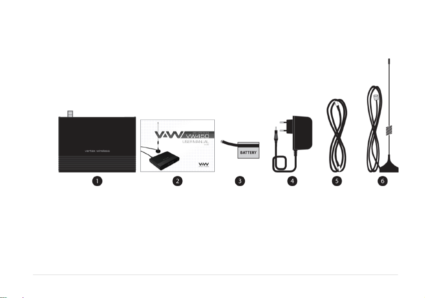
1.2. Checking the components
Check to make sure that you have all the parts shown below after opening the package. If any piece is missing or
broken, please call your agent or customer service.
1. MAIN UNIT
2. USER MANUAL
3. LI-ION BACKUP BATTERY
4. DC POWER ADAPTER
5. CABLE FOR GPRS CONNECTION (VW450): OPTIONAL ACCESSORY
6. ANTENNA AND THE CABLE WITH THEIR SUPPORT (YOU SHOULD COUPLE THE ANTENNA IN THEIR SUPPORT)
8 | page
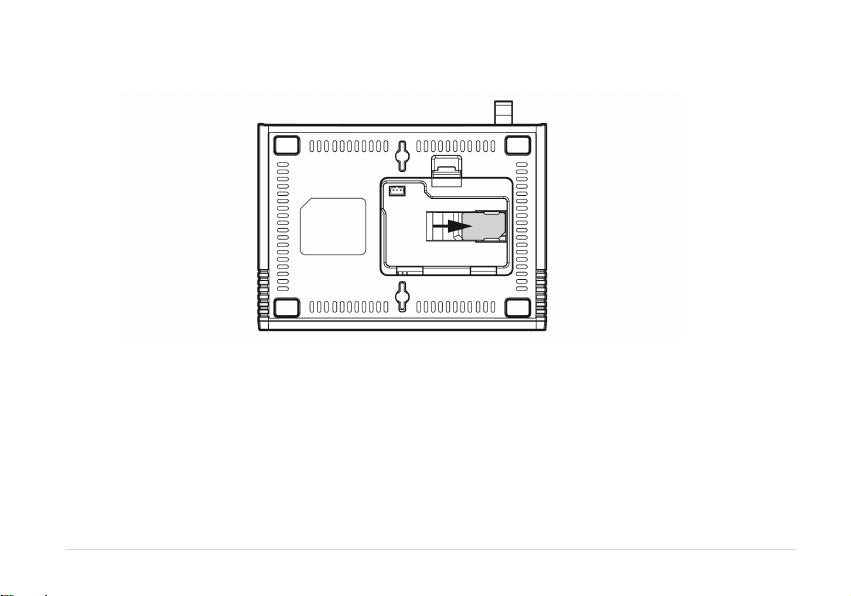
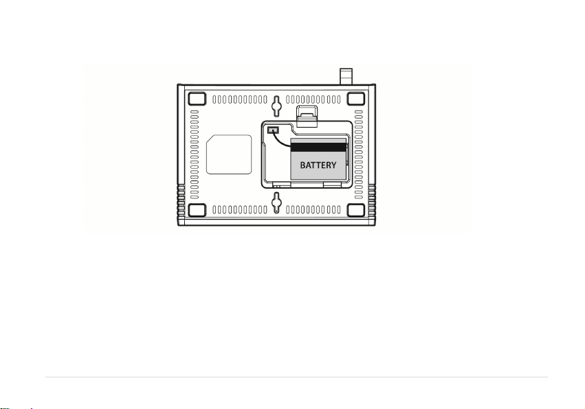
1.3. SIM card installation
1. Disconnect the power supply.
2. Open battery cover on the bottom side of the VW450.
3. Disconnect the DC power cable to VW450
4. Take out the battery pack in the right position between the hold bars
5. Insert the SIM card into the socket as shown in the picture.
* Note: Make sure the SIM card is aligned properly with the directional arrow on the holder.
6. Connect the DC power cable to VW450.
7. Insert the battery pack in the right position between the hold bars.
8. Close the battery cover.
9. Connect the power supply to VW450.
9 | page
1.4. Battery installation
1. Disconnect the power supply.
2. Open battery cover on the bottom side of VW450.
3. Connect the DC power cable to VW450.
4. Close the battery cover.
5. Connect the power supply to VW450.
10 | page

1.5. Installation of the antenna an d location of the equipment for voice service
Before you select a localization to place VW450, you should read the section for their Security in the first part of this
manual. You can place it in a plane area just as the floor, the walls or the desk or table.
1. It connects the antenna at the VW450 (previously it should couple the antenna in their support, make sure of
making the one it couples in a complete way, verify that the antenna mo is slack) and locate her it more far possible
of the terminal. If the antenna is located near the VW450 noise she/he will take place during the communication,
avoid it!
* Notices: make sure of pressing the antenna completely to their connector in the terminal.
2. Using the marked port as “Phone “connects the VW450 to the central PBX, or to the system of tariff of the booth
or a similar telephone. If their Terminal is model VW450 and you will use similar fax, connect the fax machine to the
port “Fax ".
3. Connect the adapter to the Terminal. Use the connector "DC Input."
4. Connect the adapter DC in an appropriate energy plug.
5. Turn on the terminal. Use the switch “On/Off ".
6. Checks the power of the signal GSM, verify the state of the led “Signal“(check the section 2.1). To improve the
signal reception, move the antenna and verify the state of the led “Signal".
Avoids leaving the antenna in a location in which the led illuminates red or be shut down
7. The terminal is ready to be used.
Attention : If the SIM Card (Chip) that will be used in the terminal has the number disabled PIN (it consults to their
operator), it won't be necessary to make some additional configuration in the VW450; this will be ready for their use.
In case, on the contrary, the SIM Card has the active PIN that same number PIN it will be recorded in the terminal. To
make it, connect a telephone similar to the port “Phone” and dial: #* 110 * 2 * number PIN #
With the previous procedure it will be engraving in the terminal the number PIN. It is this way when the terminal is
out and then lit, it won't be necessary to carry out this procedure again. Although the Terminal remains out a lot of
time, without current and without battery, the PIN that was recorded will always remember.
11 | page
 Loading...