

Page 1
V. 0 . 7 E
1 | page
Page 2

2 | page
Page 3

1. INSTALLATION GUIDE
1.1. FRONT, SIDE AND REAR VIEW OF VW400
1.2. CHECKING THE COMPONENTS
1.3. SIM CARD INSTALLATION
1.4. BATTERY INSTALLATION
1.5. INSTALLATION OF THE ANTENNA AND LOCATION OF THE EQUIPMENT FOR VOICE SERVICE
1.6. DESKTOP INSTALLATION
1.7. WALL MOUNTING
2. BASIC OPERATION
2.1. GETTING TO KNOW THE TERMINAL
2.2 POWER ON/OFF
2.3 MAKING CALLS
2.4 RECEIVING CALLS
2.5 ADVANCED FEATURES
3. INSTALLATION
3.1. INSTALLING VW400 MANAGER ON TO PCS (WINDOW XP)
3.2. INSTALLING VW400 MANAGER ON TO PCS (MAC)
3.2. CHECKING THE PROPER INSTALLATION OF THE DRIVER
3.2. TO UNINSTALL THE USB MODEM APPLICATION
4. CONNECTION MANAGER OPERATION GUIDE
4.1. GETTING STARTED
4.2. CONNECTING TO THE INTERNET
4.3. SETTING
5. TROUBLE SHOOTING
3 | page
07
08
09
10
11
13
14
14
16
17
17
18
20
21
24
26
27
28
29
31
Page 4

Welcome to your VW400
VW400 is a Fixed Wireless Terminal designed to provide better wireless connectivity between wire telephone and EV-DO
DATA with high sensitivity to receive signal and large transmitting power to expand extensively the effective coverage of
CDMA EV-DO Rev.A service.
Main function & features
- SIMPLE TO INSTALL AND EASY TO MAINTAIN
- COMPATIBLE TO MOST TELEPHONES, PBX
- BATTERY BACK UP DURING AC POWER OUTAGES
- ADJUSTABLE RECEIVER VOLUME
- 3 LED DISPLAY (SIGNAL/MODE/POWER)
- CALLER ID DISPLAY
- NETWORK BAND SELECTION
- CALL WAITING/FORWARDING/BARRING
- CONFERENCE CALL
- DATA COMMUNICATION (INTERNET OVER EV-DO Rev.A)
- ANALOG FAX (Optional)
4 | page
Page 5

For your safety
Here is important information for safe and efficient operation.
Please read this information before using your VW400.
For optimal performance, install this indoors. When specially used in an outdoor area, it may not work in below 0℃ or over
50℃.
Install VW400 on hard, flat surface for proper ventilation.
Avoid using VW400 in high temperature or near a source of fire or gas.
Avoid storing VW400 in cold areas.
Do not expose VW400 to moisture or dust.
Do not use VW400 in the hospital. It will interfere with medical electronic equipments such as a peace maker.
Do not use harsh chemicals, cleaning solvents to clean VW400. And wipe with a soft, clean, dry cloth to clean it.
Do not knock, drop, and shake VW400 to avoid breaking the case.
Use only the supplied or approved replacements
Do not use VW400 with a car battery.
Do not touch the antenna when VW400 is being used.
Do not use VW400 with a damaged antenna. Have your antenna replaced by a qualified technician immediately.
Use only the provided antenna. Do not use the provided antenna for any other purpose.
Use only the provided adapter. Do not use the provided adapter for any other purpose
If VW400 fails to work for any reason, do not attempt to disassemble.
5 | page
Page 6

1. Installation guide
1.1. Front, Side and Rear View of VW400
6 | page
Page 7

1.2. Checking the components
Check to make sure that you have all the parts shown below after opening the package. If any piece is missing or
broken, please call your agent or customer service.
1. MAIN UNIT
2. USER MANUAL
3. LI-ION BACKUP BATTERY
4. DC POWER ADAPTER
5. CABLE FOR DATA CONNECTION
6. ANTENNA
* Note: Drawings may vary from equipment supplied.
7 | page
Page 8

1.3. SIM card installation
1. Disconnect the power supply.
2. Open battery cover on the bottom side of the VW400.
3. Disconnect the DC power cable to VW400
4. Take out the battery pack in the right position between the hold bars
5. Insert the SIM card into the socket as shown in the picture.
* Note: Make sure the SIM card is aligned properly with the directional arrow on the holder.
6. Connect the DC power cable to VW400.
7. Insert the battery pack in the right position between the hold bars.
8. Close the battery cover.
9. Connect the power supply to VW400.
8 | page
Page 9

1.4. Battery installation
1. Disconnect the power supply.
2. Open battery cover on the bottom side of VW400.
3. Connect the DC power cable to VW400.
4. Close the battery cover.
5. Connect the power supply to VW400.
9 | page
Page 10

1.5. Installation of the antenna and location of the equipment for voice service
Before you select a localization to place VW400, you should read the section for their Security in the first part of this
manual. You can place it in a plane area just as the floor, the walls or the desk or table.
1. It connects the antenna at the VW400 (previously it should couple the antenna in their support, make sure of
making the one it couples in a complete way, verify that the antenna mo is slack) and locate her it more far possible
of the terminal. If the antenna is located near the VW400 noise she/he will take place during the communication,
avoid it!
* Notices: make sure of pressing the antenna completely to their connector in the terminal.
2. Using the marked port as “Phone “connects the VW400 to the DECT Phone, or to similar telephone. If their
Terminal is model VW400 and you will use similar fax, connect the fax machine to the port “Fax ".
3. Connect the adapter to the Terminal. Use the connector "DC Input."
4. Connect the adapter DC in an appropriate energy plug.
5. Turn on the terminal. Use the switch “On/Off ".
6. Checks the power of the signal EV-DO Network, verify the state of the led “Signal“(check the section 2.1). To
improve the signal reception, move the antenna and verify the state of the led “Signal".
Avoids leaving the antenna in a location in which the led illuminates red or be shut down
7. The terminal is ready to be used.
10 | page
Page 11
IF THE PIN OF THE SIM CARD (CHIP) IT IS ACTIVATED AND SHE/HE IS NOT CARRIED OUT THE PREVIOUS PROCEDURE
A
CORRECTLY, THE SIM CARD WILL BE ABLE TO BE BLOCKED AND YOU WILL HAVE TO ENTER THE NUMBER PUK TO UNBLOCK IT
(TO CONSULT SECTION 4.9).
void noise or interference during the communication: the antenna should be at least separated from the equipment a
meter. Avoid proximity of the team and of their antenna to electric motors, fluorescent lamps, radios, televisions, computer
monitors, speakers and in general electric equipment. Before connecting the terminal to central PBX, verify connecting a
direct telephone and making calls of test that there are not noise or interference during the call; if there is verify the location
of the equipment and their antenna.
11 | page
Page 12

1.6. Desktop installation
Before you select a location to place VW400, you must read “For your safety” section in the first part of this manual.
You can place it on the flat surface area such as above ground, on the walls, or table.
1. Connect the antenna to VW400 and locate it as far as it can reach
* Note : finger-tighten the antenna.
2. Connect a wire telephone to VW400 using phone cord
3. Connect the barrel connector of the power supply to DC Adaptor
4. Plug the DC Adaptor into the power supply.
5. Plug the DC Adaptor into an appropriate power outlet.
6. Check signal strength moving the antenna until you find the best signal possible.
(See 2.1 LED Status Indicator section)
7. If you use Data Service or PC FAX Service, connect your data cable to the Data port located at the side of VW400.
8. If you use G3 FAX machine, connect your line cord of G3 FAX to the RJ-11port located at the side of VW400.
12 | page
Page 13

1.7. Wall mounting
1. Mark two mounting hole locations to match the screw hole in the back of VW400.
2. Drill two holes at the marked locations.
3. Tighten the screws until the head is about 3~5mm from the wall.
4. Hang VW400 on the screw using the two holes in the back.
5. Push VW400 down until the unit is firmly locked into place.
13 | page
Page 14
2. Basic Operation
2.1. Getting to know the terminal
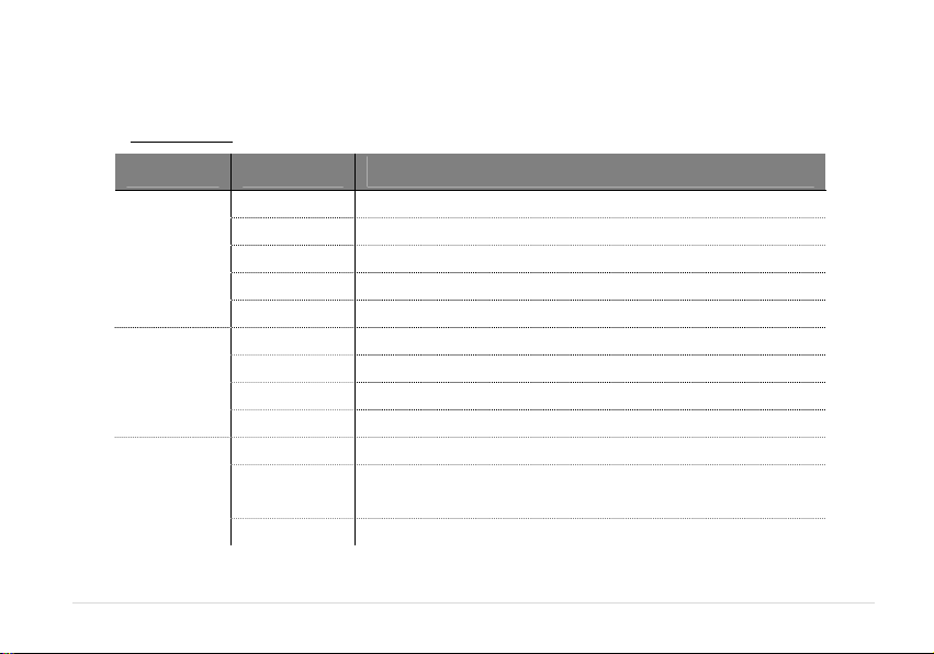
LED Indications
LED Color Meaning
Power
Signal
Mode
14 | page
Green(Blinking) Power is being supplied by the AC adapter
Green(Solid) Full Charged Power is being supplied by the battery
Orange Mid Power is being supplied by the battery
Red Low Power is being supplied by the battery
Green Very good signal level
Orange Good signal level
Red Low signal level
Green EV-DO Service
Orange
Red No Service
Off Power is off or power is being supplied by battery
Off No Service, No Signal
CDMA 1x Service
Battery is being charged, if power adaptor is connected
Page 15
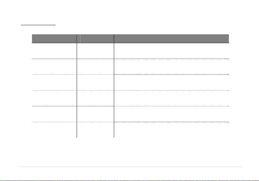
SOUND Indications
Typ e Condition Meaning
Normal dial Tone Continuous Terminal is in service area with adequate signal
No Service Tone
Outgoing call
restriction tone
Voice mail tone
1.5sec on
800msec off
800msec on
200msec off
4 long beeps
and dial tone
Confirmation 3 short beeps
Error howling beep
Terminal cannot make or receive calls (No signal)
Terminal is configured to block outgoing call but it
can receiving incoming calls
When you lift the receiver, this sound indicates
voice mail message
When using the menu with ** sequence, this
sound indicates success
When using the menu with ** sequence, this
sound indicates error
15 | page
Page 16

2.2. Power On/Off
Power switch is located on the bottom side of terminal
◦ Turn on the unit by moving switch to ON position.
◦ Turn off the unit by moving switch to OFF position.
Note : When you turn on the terminal, it automatically searches for service signal.
After successfully acquiring s ervice signal, the Signal LED turns to green, orange or red depending on signal strength.
Starting with RUIM
When the PIN Code of R-UIM Card is turned on, you may need to enter the PIN Code when you
power on the terminal.
1. Lift the receiver of the analog telephone.
2. Using the numeric keypad of the analog phone, enter the Pin Code.
3. If the PIN code is correct, confirmation tone sounds. If wrong, howling tone sounds.
Note 1: PIN code checking can be turned on/off. Please see page 20.
Note 2: You may enter pin code up to 3 times. After 3 times, you will need to re-start the terminal.
Note 3: Default pin code is provided by the service provider.
Please contact your service provider in case you do not remember the pin code.
Once the modem is plugged, the installation will be started automatically.
16 | page
Page 17

2.3. Making Calls
1. Check to see that your terminal is turned on.
2. Pick up the handset of the phone.
3. If you hear the dial tone, dial the desired telephone number, using the numeric keypad.
4. Wait for about 3~9 seconds until the call is automatically made by the terminal.
Note: Press <#> button to make call right away after entering the dial number.
5. When the other person answers, begin conversation.
Note: If Connection Alert is turned on, a beep is heard phone is connected with base station.
6. To hang up, put the handset back on the phone.
2.4. Receiving Calls
The analog telephone(s) connected to the terminal ring when there is an incoming call.
1. Pick up the telephone handset to answer the call.
2. To disconnect after finished, replace the handset on the phone.
Note 1: Make sure that the attached telephone’s ringer is enabled.
Note 2: When there is an incoming call when you are already holding the receiver, press any key on the numeric keypad to answer the
call.
17 | page
Page 18
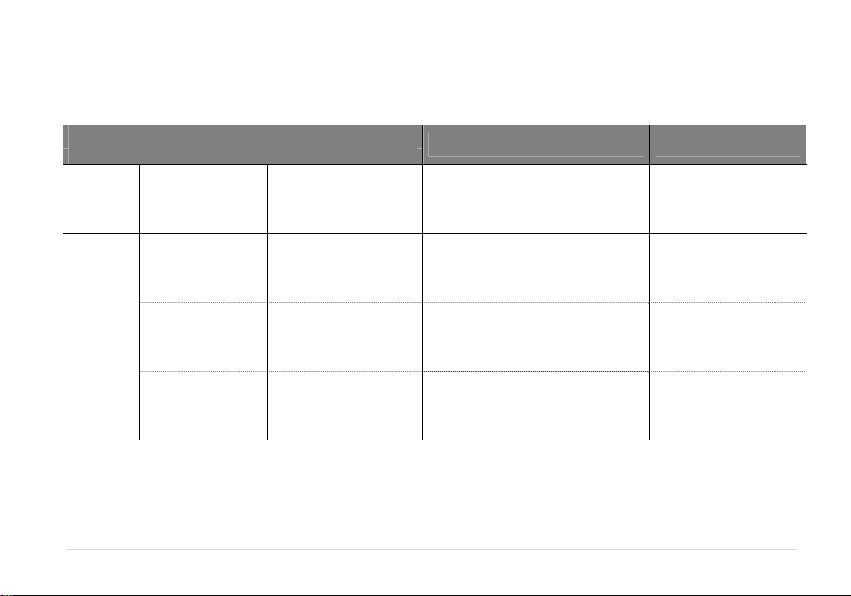
2.5. Advanced Feature
You can follow below code table to control VW400.
Enter the menu item by pressing ## and the menu option.
MENU
EXAMPLE REMARK
1. Sound
2. General
18 | page
1. Adjusting Voice
Volu me
1. Setting Caller ID
2. Setting Auto
Send time
3.Setting DTMF
Length
<*>Louder / <#>Lower
0. No Caller ID
1. DTMF Standard
2. FSK(Bell core)
3. V23
3~9 seconds, 0 OFF
<*>Long / <#> Short
<#><#><1><1><*>(louder)
<#><#><1><1><#>(lower)
<#><#><2><1><0> (no caller id)
<#><#><2><1><1> (DTMF)
<#><#><2><1><2> (FSK)
<#><#><2><1><3> (V23)
<#><#><2><2><4> (4 seconds)
<#><#><2><2><0> (off)
<#><#><2><3><*> (Long)
<#><#><2><3><#> (Short)
Available if Caller ID
capable analog phone is
used
Page 19
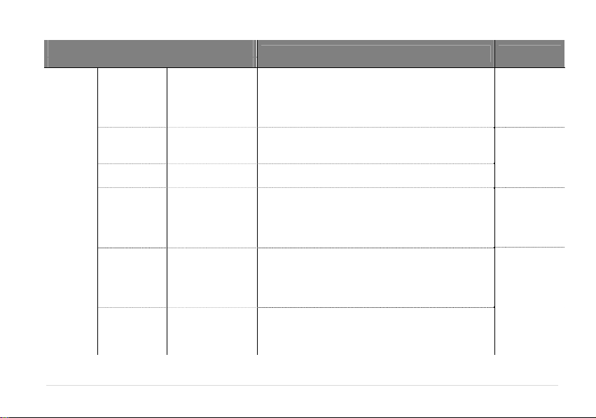
Enter the menu item by pressing ## and the menu option.
T
K
T
MENU
EXAMPLE REMARK
Old lock
1. Changing
Lock code
code,(Tone),
New lock code,(#),
New lock code
To change from “0000” to “1234”
<#><#><3><1><0><0><0><0>(confirmation tone)
<1><2><3><4><#><1><2><3><4><#>
again,(#)
3.Security
2. Restricting
Outgoing
Calls
3. Terminal
Reset
4. Change the
PIN code*
5. PIN
Enable/Disable
6. Input PUK
with New PIN
code
*
Lock code, <*>Off
or
<#>On
Lock code, <#>
Lock code,(Tone),
Old PIN code,(#),
New PIN code,(#),
New PIN code
again,(#)
Lock code,(Tone),
PIN
code,<*>Disable or
<#>Enable
PUK code,(Tone),
New PIN code
If lock code is <0><0><0><0>:
<#><#><3><2><0><0><0><0><*>(off)
<#><#><3><2><0><0><0><0><#>(on)
If lock code is <0><0><0><0>:
<#><#><3><3><0><0><0><0>
If lock code is <0><0><0><0>:
To change from “1234” to “5678”
<#><#><3><4><0><0><0><0>(confirmation tone)
<1><2><3><4><#><5><6><7><8><#>
<5><6><7><8><#>
If lock code is <0><0><0><0>:
PIN code is <5><6><7><8>:
<#><#><3><5><0><0><0><0>(confirmation tone)
<5><6><7><8><*>(disable)
<5><6><7><8><#>(enable)
code is <5><6><7><8>:
If PU
New PIN code is <0><0><0><0>:
<#><#><3><6><5><6><7><8><#><0><0><0><0><#>
<0><0><0><0><#> (confirmation tone>
his menu is
applicable
when UIM card
is inserted and
PIN is enabled.
This menu is
applicable
when UIM
cards inserted.
his menu is
applicable
when UIM
cards inserted.
19 | page
Page 20

3. EV-DO Data Service
3.1. Installing VW400 Manager onto PCs (Window Users)
The entire process will take approximately 10 minutes to complete. (Take Windows XP as an example)
1) Please insert the modem into the PC.
Once the modem is plugged, the installation will be started automatically.
2) Once the installation is completed, the Connection Manager and USB Driver is installed into the PC.
You will see “Your new hardware is Installed and ready to use” message.
3) Connection Manager icon will be created on desktop in Window.
1 2 3
20 | page
Page 21
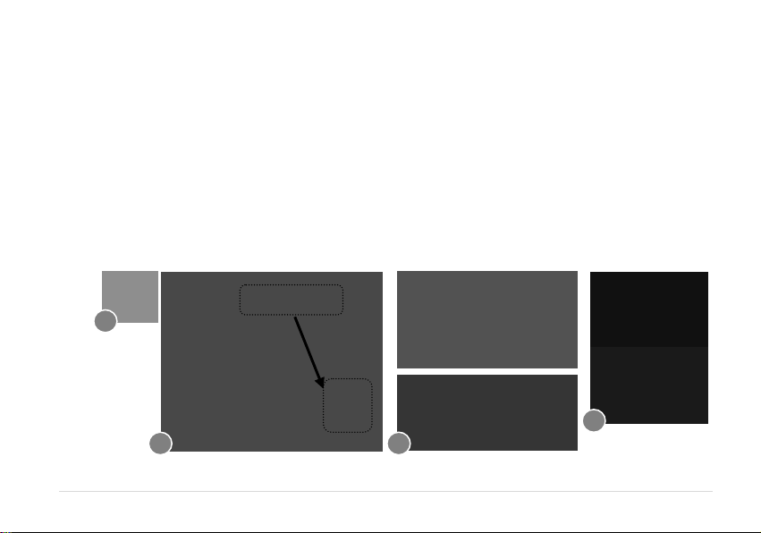
3.2. Installing VW400 Manager onto PCs (Mac Users)
The entire process will take approximately 10 minutes to complete. (Take MAC Tiger as an example)
1) Insert CD and wait for the CD device icon to be appeared on your desktop. Click on the icon to open the CD
storage and double – click on the “osx-V1_09c+3-release.dmg” File.
2) Copy following two items: VertexWireless_SerialPort installer and Uninstaller and paste at “Applications Folder”.
3) Installing “Vertex Wireless _ Serial port Installer” and then restart your computer.
4) Insert your USB modem into any available USB port, and wait for the VWMF icon to be appeared on your desktop.
Right click on the VWMF icon and select Eject “VWMF”.
Note: Every time the modem is inserted Into the PC, VWMF must be ejected to use the modem.
1
4
2 3
21 | page
Page 22

5) Go to “System Preference” -> Click “Network”
6) “Show” setting Vertex wireless Multi-Function. -> “PPP Options” Check each Option
22 | page
Page 23
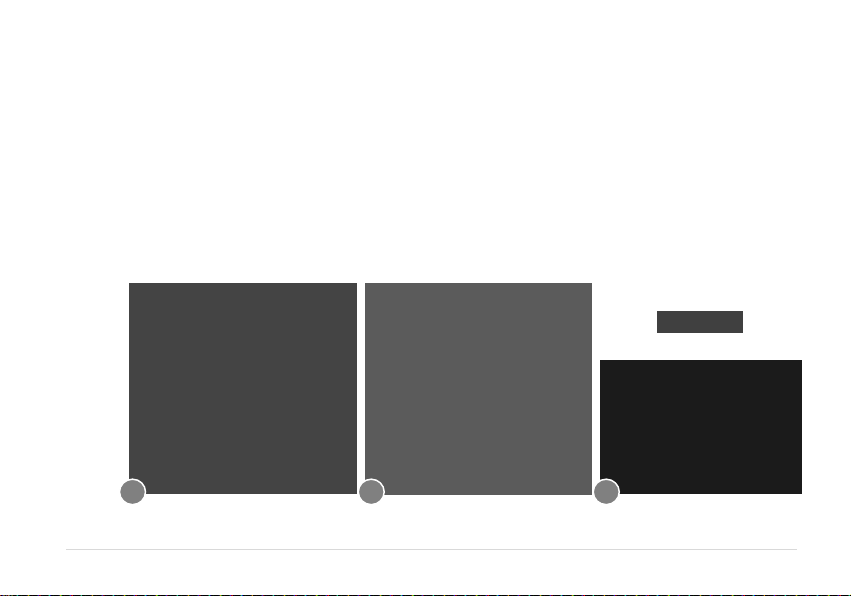
7) “Modem “ Select “ Vertex Wireless Multi-Function”
8) Go to PPP and configure connection parameters as below.
1
Service Provider : Enter the name to be displayed on the “Profile Name”
○
2
○
Account Name : If required, enter the User ID for the Network provider.
3
○
Password : Enter the password for the user name.
4
○
Telephone No. : Specify the phone number to which modem will connect.
9) Modem icon will be displayed on the taskbar at the upper right corner. Indicating that the connection manager is
launched and ready to use.
7 8 9
23 | page
Page 24
3.3. Checking the proper installation of the Driver
If the Driver has been installed properly, it is possible to check the proper operation from Control Panel (the example
below is for Windows XP)
1) Start Control Panel
2) Select “System”
3) Select “Device Manager” from Hardware Tab
3
1 2
24 | page
Page 25

4) As shown in below with boxes that shows “Vertex Wireless CDMA USB Modem” and “Vertex Wireless CDMA USB
Serial Device”, the Driver has been successfully installed.
25 | page
Page 26

3.4. To Uninstall the USB Modem Application
1) To Uninstall VW400 Modem Driver, Click “Control Panel” And click “ADD or Remove Programs”
2) Find VW400 Connection Manager Program.
Click Change / Remove (Remove the VW400 Modem from the USB Port)
3) Once uninstall is completed, you must restart computer before the new setting will take effect.
2
1 3
26 | page
Page 27

4. Connection Manager Operation Guide
4.1. Getting Started
After plug the modem into the PC, and run “Connection Manager”, the following window is appeared. Connection
Manager allows browsing internet, modifying modem configurations.
4.1.1 Basic User Interface
1) Connect / Disconnect Button : Connect to the
communication connection /Disconnect from
the communication connection
2) Status Bar : Indicate the strength of the signal. More
bars Indicate stronger signal.
3) Time : Indicate the Using time.
4) Packet : Indicate the packet rate.
4.1.2 Security
1) Pin Control
You can enable or disable the PIN from the setting (please refer to
“PIN Control” in Setting section). If Pin is enabled, the PIN is
requested each time the Connection Manager is run. Once the
following pop up window is appeared, press the proper PIN code. If
the proper PIN code is inserted, you will be able to use the modem
with the connection manager.
27 | page
Page 28

2) Fail to input the proper Pin number
If you fail up to three times to input proper PIN code,
the Authentication would be automatically into PUK
code authentication. At this time you have 10 times to
enter PUK code. If you fail up to 10 times to enter proper
PUK code, you can’t use your UIM card any more. In that
case consult your service provider.
4.2. Connecting to the Internet
4.2.1 Connect
First, connect the modem into the PC then double-click the
Connection Manager icon on the PC. If VW400 is inserted
correctly, the LED on the Modem is blinking from Red to Blue.
Once the modem is ready, CONNECT button will be enabled.
Click the CONNECT button to be connected to the internet.
Once the connection is completed, CONNEC T button will be
changed to DISCONNECT button
4.2.2 Disconnect
Click the Disconnect button to be disconnected from the
connection. Once the disconnection is completed,
DISCONNECT button will be changed to CONNECT button
28 | page
Page 29

4.3. Setting
Click “Setting” to open the setting window to set various items.
4.3.1 General
You can change basic function in this section.
4.3.2 Information
You can check the software version of Firmware and Manager.
29 | page
Page 30

4.3.3 Pin Control
You can enable or disable the PIN feature or change the PIN number in this section. The PIN number should be
4~5 digits numbers.
4.3.4 Profile Manager
You can create new profile by pressing New button or delete existing profile by pressing Delete button.
1) Profile Name : Enter the name to be displayed on the “Profile Name”
2) Dial No. : Specify the phone number to which modem will connect.
3) ID : If required, enter the User ID for the network provider.
4) Password : Enter the password for the user name.`
30 | page
Page 31
5. Troubleshooting
Below is a list of common error and possible solutions regard the use of your Wireless Modem.
Error Solution
Initialization Fail
Out of Service Area
There was no answer
Can not connect to the
Internet
- If this condition appears, please right click the Connection Manager icon on your
system tray and click “Exit”. Then remove and reinsert the modem and wait until your
computer “beeps” before clicking the Connection Manager shortcut icon again.
- If this condition appears, there is no service available at this time or Area. The network
may be busy or undergoing maintenance. Try connecting to the network at a later time,
or Moving to another location if you are outside the enhanced.
- If this condition appears, the network may be busy. Try and connect again at a later
time.
- Please Check “Profile Manager” of program for correct ID, password and Service
Number. For proper ID, password and Service number, please contact service provider for
more information.
Any other trouble, please consult with service center.
31 | page
Page 32
FCC ID: XAVVW440
Warning: Exposure to Radio Frequency Radiation The radiated output power of this device is far below the
FCC radio frequency exposure limits. Nevertheless, the device should be used in such a manner that the
potential for human contact during normal operation is minimized. In order to avoid the possibility of
exceeding the FCC radio frequency exposure limits, human proximity to the antenna should not be less
than 100 cm during normal operation. The gain of the antenna for Cellular band must not exceed 1dBi.
The gain of the antenna for PCS band must not exceed 1dBi.
FCC Compliance Information
NOTE: This equipment has been tested and found to comply with the limits for a Class B digital device, pursuant to part 15 of
the FCC Rules.
These limits are designed to provide reasonable protection against harmful interference in a residential installation. This
equipment generates, uses and can radiate radio frequency energy and, if not installed and used in accordance with the
instructions, may cause harmful interference to radio communications. However, there is no guarantee that interference will
not occur in a particular installation. If this equipment does cause harmful interference to radio or television reception, which
can be determined by turning the equipment off and on, the user is encouraged to try to correct the interference by one or
more of the following measures:
- Reorient or relocate the receiving antenna.
- Increase the separation between the equipment and receiver.
- Connect the equipment into an outlet on a circuit different from that to which the receiver is connected.
- Consult the dealer or an experienced radio/TV technician for help.
Caution the user that changes or modifications not expressly approved by the party responsible for compliance could void
the user’s authority to operate the equipment.
32 | page
Page 33

32 | page
 Loading...