

Page 1
Page 2

Table of Contents
Technical Specification ………….2
Table of Contents
Status ..………………………11
1. Product Overview …………..….3
Package Contents ……………… 3
System Requirements………..… 3
Features ………….……….……...4
Hardware Overview ……………. 5
2. Installation ….………..………….8
3. Configuration .……..…………....9
Web-based Configuration ……... 9
Basic Setup ...……………………10
Connection Setting ...……….10
Advanced Setup ………………..12
IP Setup ……………………..12
Wireless Setup ……………..14
Traffic Control ………………19
Security ……………………...22
Utility ………………………....26
4. Administrator .…………………31
5. Status …………………………...33
Troubleshooting ………...……….34
1
Page 3

Technical Specifications
Technical Specifications
Standards
IEEE 802.11g
IEEE 802.11b
Wireless Signal Rates
54Mbps 48Mbps
36Mbps 24Mbps
18Mbps 12Mbps
11Mbps 9Mbps
6Mbps 5.5Mbps
2Mbps 1Mbps
Security
64/128-bit WEP
WPA-PSK
WPA-PSK2
Frequency Range
2.4GHz to 2.483GHz
CDMA Frequency Range
VW210 – Rx: 463 ~ 468MHz
Tx: 453 ~ 458MHz
VW240 – Rx: 859.64 ~ 893.37MHz
Tx: 824.64 ~ 848.37MHz
Rx: 1930 ~ 1989.95MHz
Tx: 1850 ~ 1909.95MHz
Channel Bandwidth
CDMA 1.23MHz
External Antenna T ype
Two detachable reverse SMA Antenna
LEDs
Power Signal
1x/EVDO WAN
WLAN LAN
Operating temperature
-20 °C ~ +60 °C
Storage temperature
-30 °C ~ +70 °C
Humidity
5 ~ 95%
Dimension
150(W)x130(D)x30.5(H)mm
Operating time
Working time: 2.5Hrs
Standby time: 4.2Hrs
AC Adaptor
AC 110~240V, 50~60Hz
DC 5.0V / 2.0A
2
Page 4
Section 1 – Product Overview
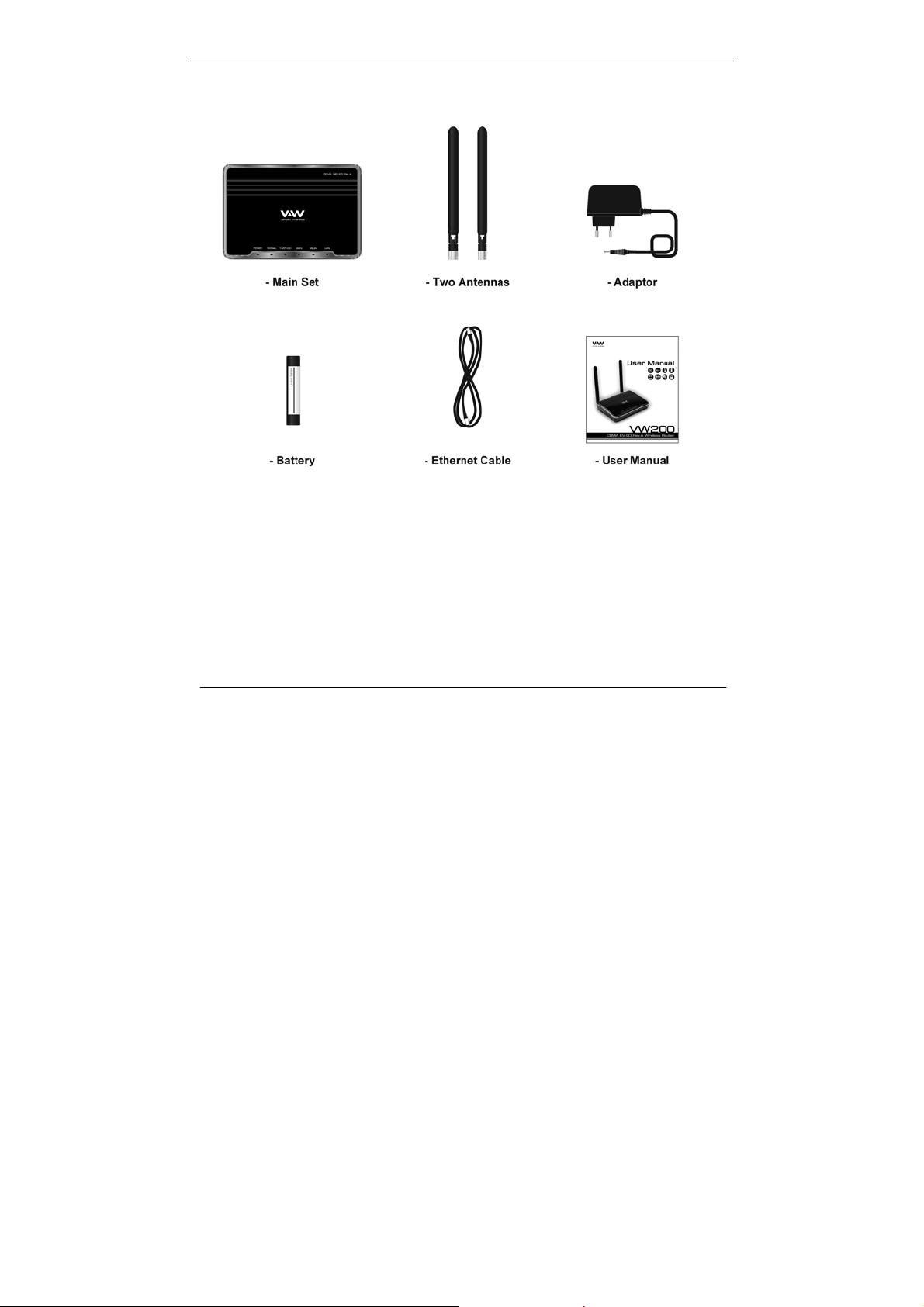
Packages Contents
System Requirements
• Broadband Internet connection with RJ45 (Ethernet connection)
• At least one computer with an installed wireless network interface card or
adaptor
• TCP/IP networking protocol installed on each computer
• Internet browser
3
Page 5

Section 1 – Product Overview
Features
• Faster Wireless Networking – The VW200 provides up to 54Mbps wireless
connection with other 802.11g wireless clients.
• Compatible with 802.11b Devices – The VW200 is still fully compatible with
the IEEE 802.11b standards, so it can connect with existing 802.11b PCI, USB
and Cardbus adapters.
• Advanced Firewall feature – The Web-based user interface displays a
number of advanced network management features including:
Filter Scheduling – These filters can be scheduled to be active on certain
days or for a duration of hours or minutes.
Parental Controls – Easily applied content filtering based on MAC
Address, and/or URL.
Secure Multiple/Concurrent Sessions – The VW200 can pass through
VPN sessions. It supports multiple and concurrent IPSec and PPTP
sessions, so users behind the VW200 can surely access corporate
network.
*Maximum wireless signal rate derived from IEEE Standard specification. Actual data throughput will vary.
CDMA Network conditions and environmental factors, including volume of network traffic, building materials and
construction, and network overhead, lower actual data throughput rate. Environmental conditions will adversely
affect wireless signal range.
4
Page 6
Section 1 – Product Overview
Hardware Overview
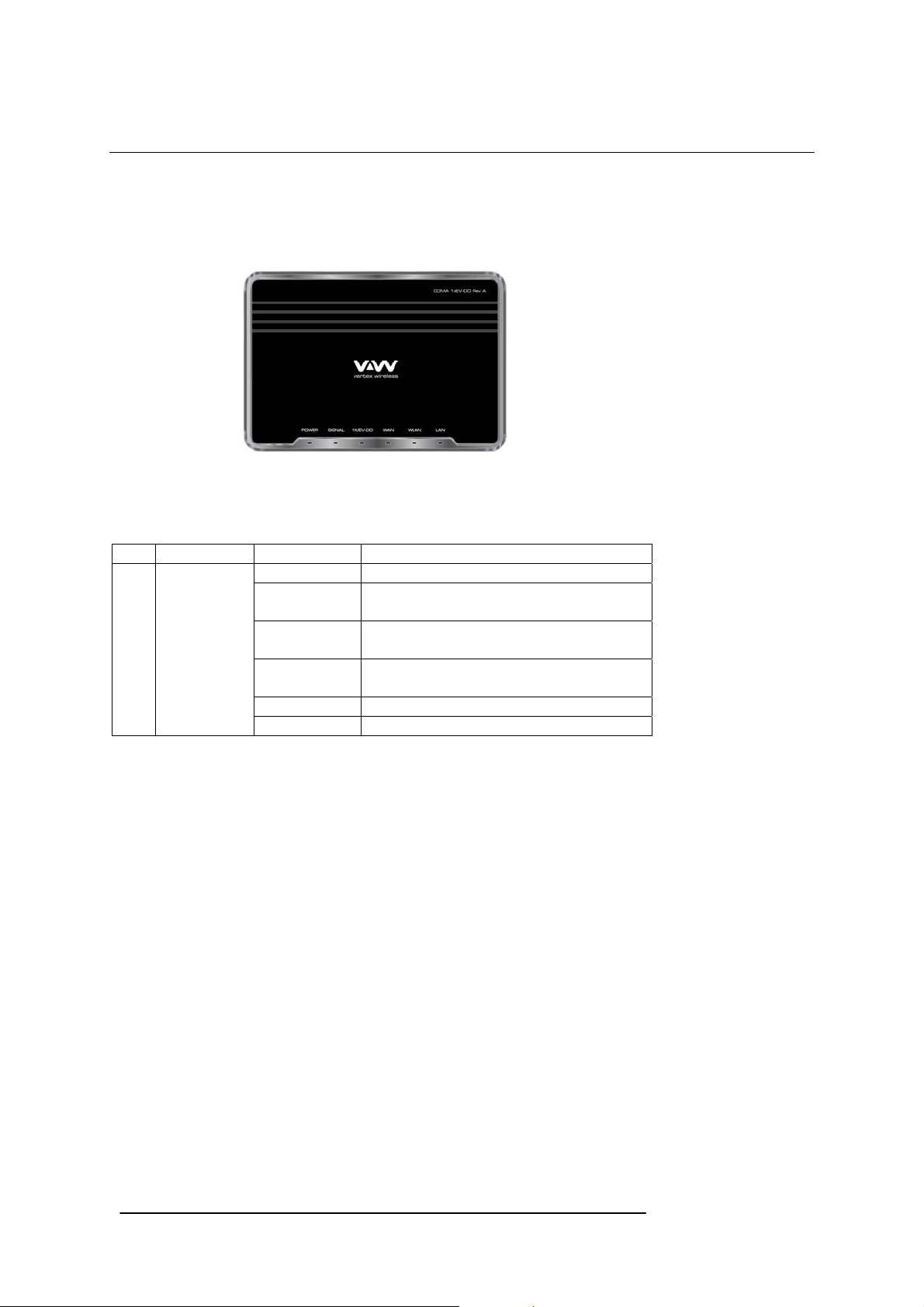
Router Front Panel
The panel of the VW200 contains the status lights to verify various conditions
Item Function Activity Description
1 Power OFF Power is not supplied to the router
Solid Blue Power is supplied to the router with either
Adapter or Battery (Full charged)
Solid Violet Power is supplied to the router with half
battery
Solid Red Power is supplied to the router with low
battery
Blinking Blue Charging the battery
Blinking Red Error with charging battery (bad battery, etc)
5
Page 7

Section 1 – Product Overview
Router Front Panel (continued)
2 Signal OFF No 1x or EV-DO signal
Solid Blue Strongest level
Solid Violet Medium level
Solid Red Low level
3 1x/EV-DO OFF Router is connected to 1x
Solid Blue Router is connected to EV-DO
4 WAN OFF Modem is not connected to the Network.
i.e: dormant or idle mode
Solid Blue Modem is connected to the Network.
i.e: traffic channel is established
5 WLAN OFF No Wi-Fi is used
Solid Blue Wi-Fi is activated
Blinking Blue Active data passed through Wi-Fi
6 LAN OFF No RJ45 (Ethernet) connection is used
Solid Blue RJ45 connection is in use
Blinking Blue Active data passed through the port
6
Page 8

Section 1 – Product Overview
Router Back Panel
The rear panel of the VW200 contains the items in the list that follows
1. CDMA Diversity Antenna connector
2. Power Switch
3. AC power adapter outlet
4. Ethernet ports for connecting the router to local computers
5. CDMA Main Antenna connector
Note: Restore factory settings button is placed at the bottom of the router
7
Page 9

Section 2 – Installation
Wireless Installation Considerations
The VW200 wireless router let your network using a wireless connection from virtually
anywhere within the operating range of your wireless network. However, the number,
thickness and location of walls, ceilings, or other objects that the wireless signals must
pass through, may limit the range. Typical ranges vary depending on the types of
materials and background RF noise in your home or business.
1. Router should be placed at the position with good CDMA signal.
2. Keep the number of walls and ceilings between the VW200 and other
network devices to a minimum-each wall or ceiling ca n reduce your ad apter’s
range from 1~30 meters. Position your devices so th at the number of walls or
ceilings is minimized.
3. Building Materials make a difference. A solid metal door or aluminum studs
may have a negative effect on range. Try to position access points, wireless
routers, and computers so that the signal passes through drywall or open
doorways. Materials and objects such as glass, steel, metal, walls with
insulation, water (fish tanks), mirrors, file cabinets, brick, and concrete will
degrade your wireless signal.
4. Keep your product away (at least 1~2 meters) from electrical devices or
appliances that generate RF noise.
5. If you are using 2.4GHz cordless phones or X – 10 (wireless products such
as ceiling fans, lights, and home security systems), your wireless connection
may degrade dramatically or drop completely. Make sure your 2.4GHz phone
base is as far away from your wireless devices as possible. The base
transmits a signal even if the phone is not in use.
8
Page 10
Section 3 – Configuration
Configuration
Web-based Configuration
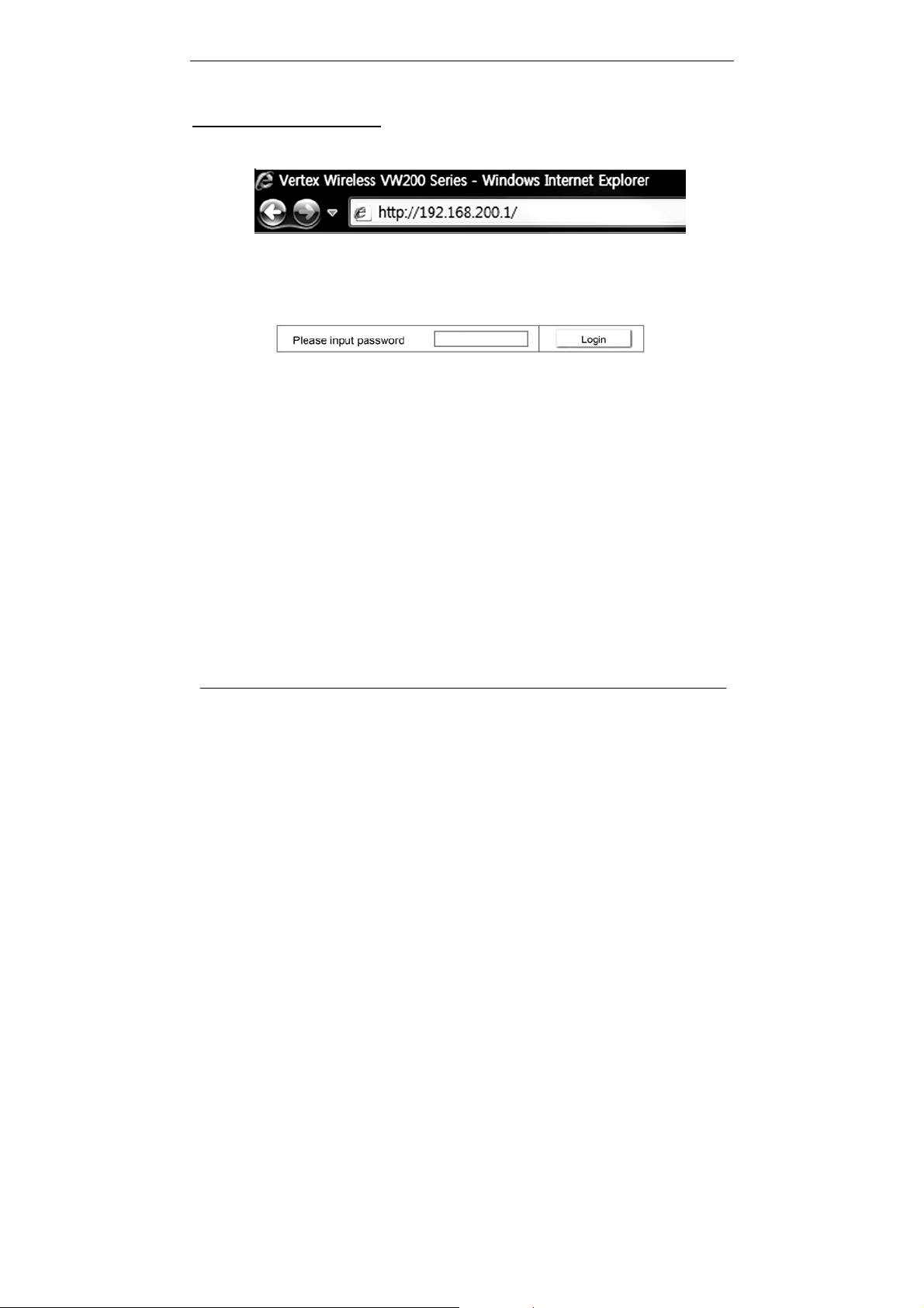
Please open a web-browser and enter the IP address of the router (192.168.200.1)
You will see the Router’s login page in your browser window. Enter login password and
press “Login” button to log in.
Note: The Router ships with no password entered. In the login screen, leave the password blank and click the
“Login” button to log in.
9
Page 11
Section 3 – Configuration
Basic setup
Connection Setting
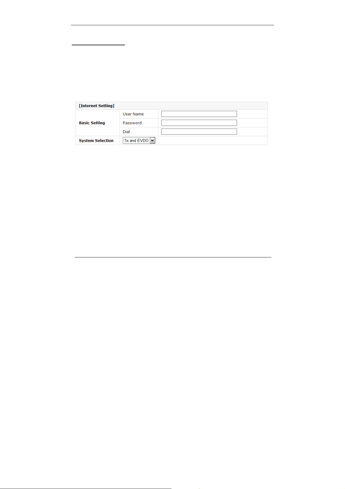
[Internet Setting]
Basic setting: Enter your PPP user name, password and Dial (Provided
by operator. Default dial: #777)
System Selection: Select the CDMA system from the drop-down menu:
1x and EVDO, 1x, and EVDO
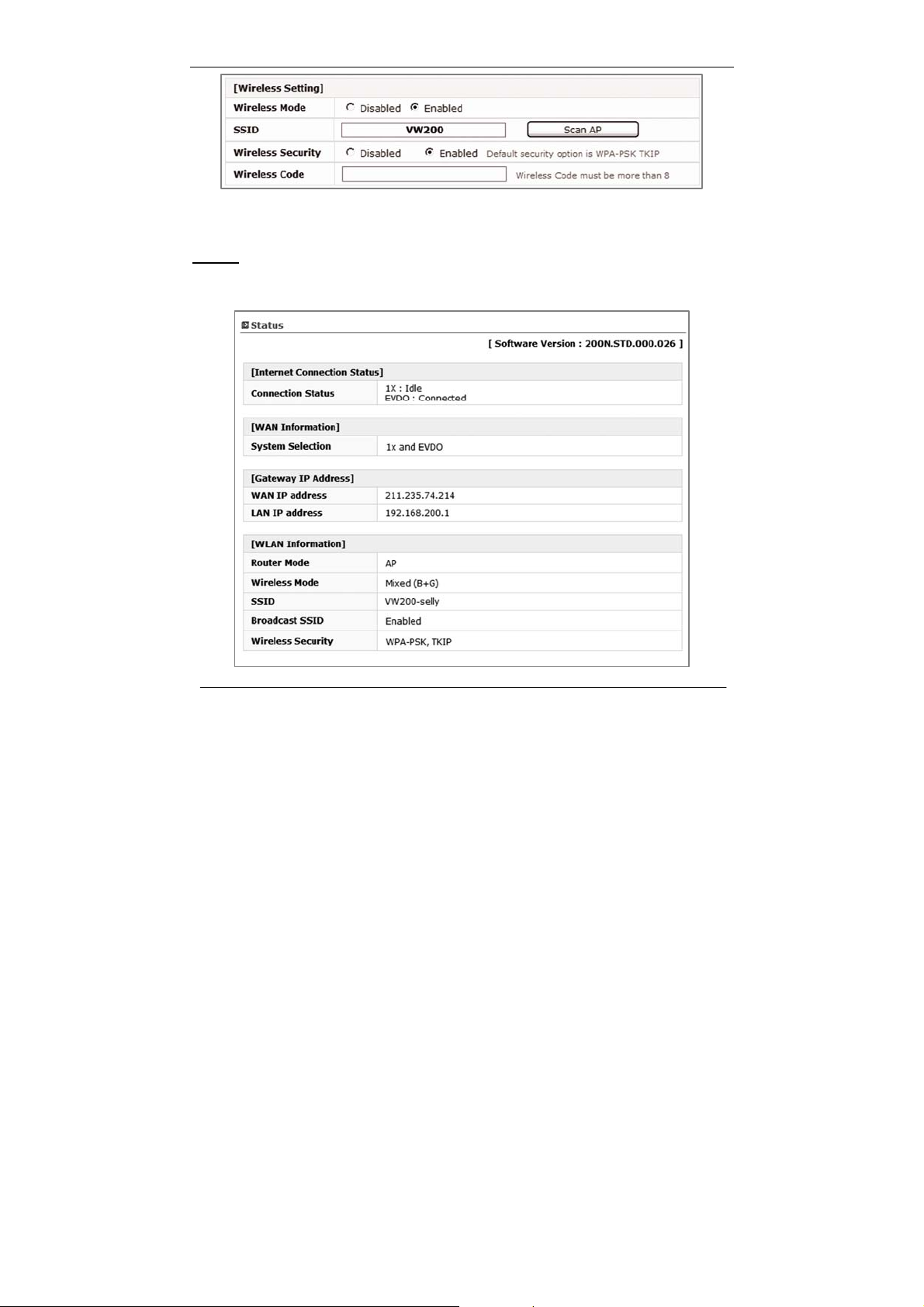
[Wireless Setting]
Wireless Mode: Select Enabled to use Wi-Fi feature otherwise select
Disabled. If you select Enabled, SSID and Wireless
Security will be displayed below
SSID: Service Set Identifier is the name of your wireless
network. Create a name using up to 32 characters.
Wireless Security: Select Enabled to use Wireless Security otherwise select
Disabled. If you select Enabled, Wireless Code will be
displayed below (Default security option is WPA-PSK
TKIP. If you want to have more option, go to Wireless
Setup under Advanced Setup)
10
Page 12
Section 3 – Configuration
Wireless Code: Enter security code for WPA PSK TKIP encryption if you want to
use Wi-Fi security option
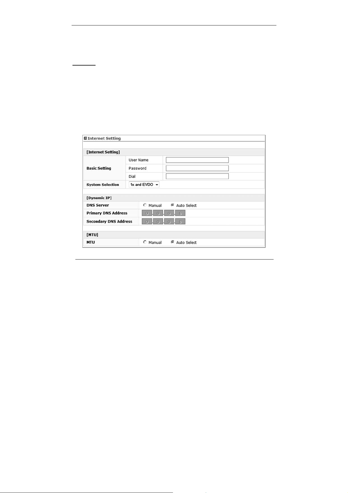
Status
You can check current Router status via this menu.
11
Page 13
Section 3 – Configuration
Advanced Setup
This menu provides various enhanced network function configuration and recommend
to expert user. It’s not necessary for all users.
IP Setup
≫ Internet Setting
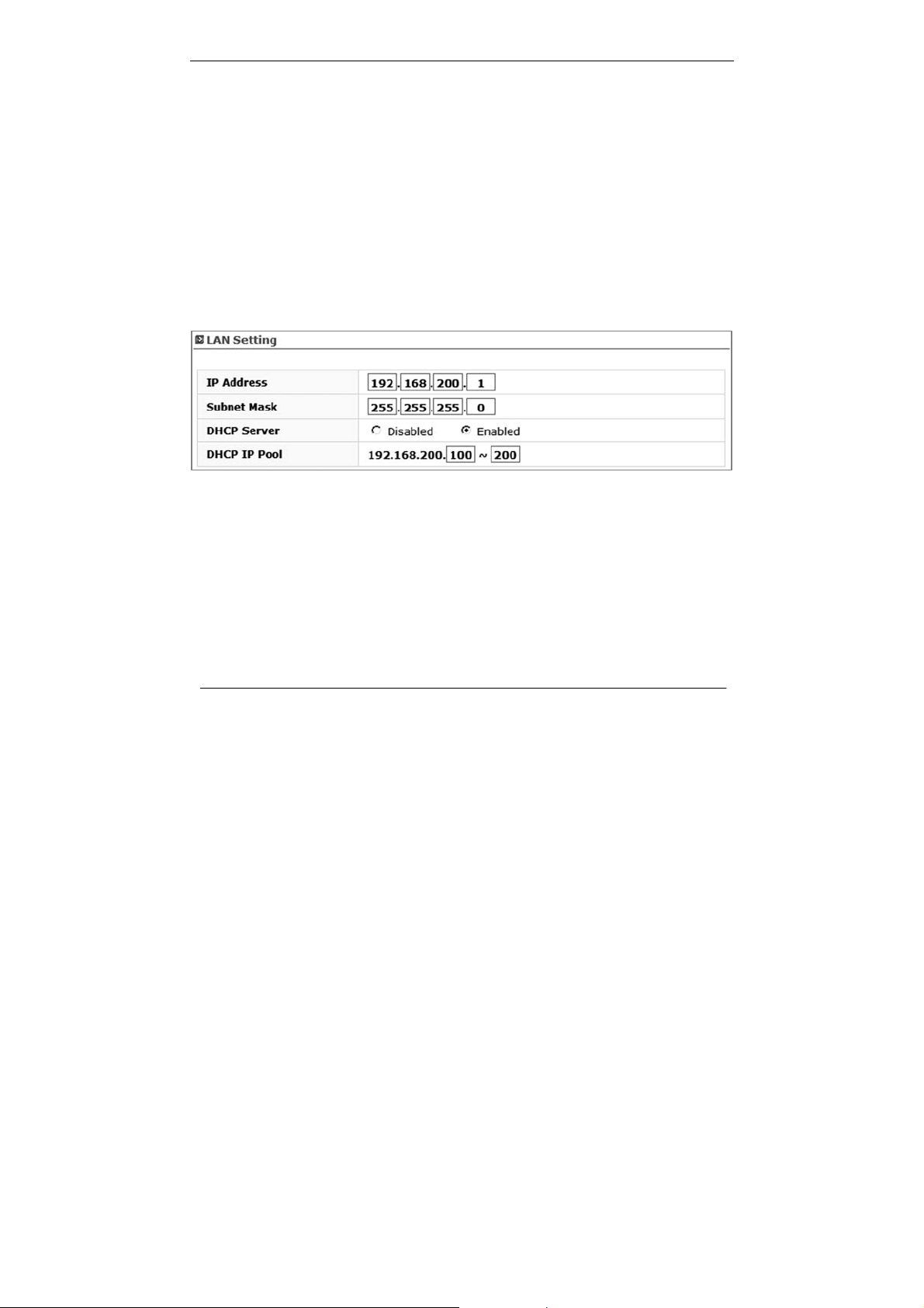
[Internet Setting]
Basic setting: Enter your PPP user name, password and Dial (Provided
by operator. Default dial: #777)
System Selection: Select a CDMA system from the drop-down menu:
1x and EVDO, 1x, and EVDO
12
Page 14
Section 3 – Configuration
[Dynamic IP]
DNS Server: Select either Manual or Auto select for DNS server.
Primary DNS Address: Enter the Primary DNS server IP assigned by your ISP
Secondary DNS Address: Enter the Secondary DNS server IP assigned by
your ISP (optional)
MTU: Maximum Transmission Unit – you may need to change the MTU for
optimal performance with your specific ISP. Automatic is the default MTU
≫ LAN Setting
IP Address: This is the internal IP address of the Router.
The default IP address is “192.168.200.1” and it can be
changed if needed.
Subnet Mask: This is a unique, advanced feature of the Router. The
default is “255.255.255.0” and it can be changed if
needed.
DHCP Server: The Dynamic Host Control Protocol (DHCP) server will
automatically assign an IP address to the computers on
the LAN/private network. Select Enabled to use DHCP
server otherwise select Disabled
13
Page 15
Section 3 – Configuration
Note: To use DHCP server, be sure to set your computers to be DHCP clients by setting their TCP/IP settings to
“Obtain an IP Address Automatically.
DHCP IP Pool: Enter the starting and ending IP addresses for the DHCP
server’s IP assignment. The default range is 100-200.
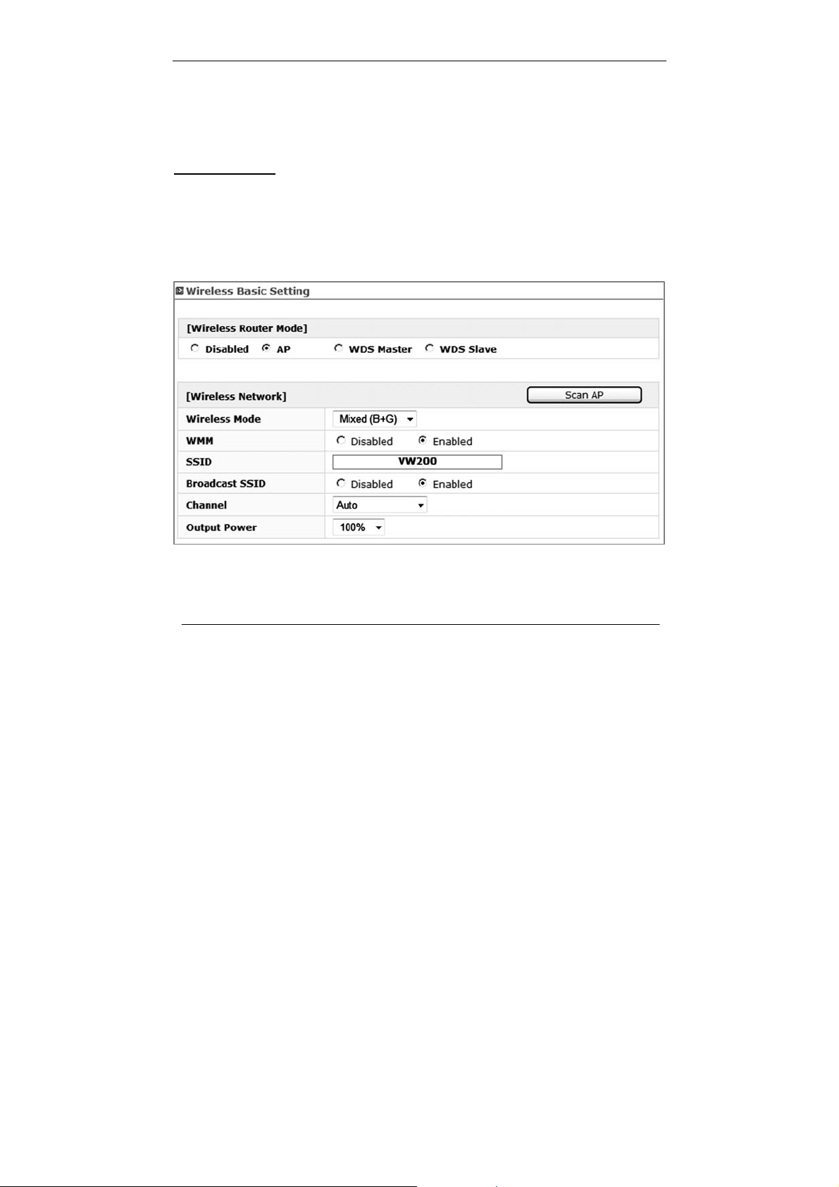
Wireless Setup
≫ Wireless Basic Setting
[Wireless Router Mode]
Select a Wireless Router mode from the list: Disabled / AP / WDS Master / WDS
Slave
[Wireless Network]
Wireless Mode: Select a Wireless Mode from the drop-down menu:
Mixed(B+G) Mode – Select if you are using both
14
Page 16

Section 3 – Configuration
802.11b and 802.11g wireless clients.
G only Mode – Select if you are using 802.11g wireless
clients only.
B only Mode – Select if you are using 802.11b wireless
clients only.
WMM: Wireless Multimedia Extension (WMM) mode is Power
Save uses mechanisms from 802.11e and legacy 802.11
to save power (for battery powered equipment) and finetune power consumption. Select Enabled to use WMM
otherwise select Disabled
SSID: Service Set Identifier is the name of your wireless
network. The SSID must be identical for all devices in the
wireless network. Create a name using up to 32
characters. (It is case-sensitive and uses any of the
characters in the keyboard)
Broadcast SSID: Select Disabled if you do not want the SSID of your
wireless network to be broadcasted by the router
otherwise select Enabled. If Disabled is selected, the
SSID will not be detected by site survey so your wireless
clients need to have the SSID manually entered to
connect to the router.
Channel: A number of operating channels can be selected. If there
are other wireless networks operating in your area, the
channel will be set different from the channel of the other
wireless networks. For best performance, use a channel
that is at least five channels away from the other
wireless network.
Output Power: There are a number of operating output power you can
choose from. The default output power 100%. The
output power can be changed if needed. For best
performance, use a 100%.
15
Page 17

Section 3 – Configuration
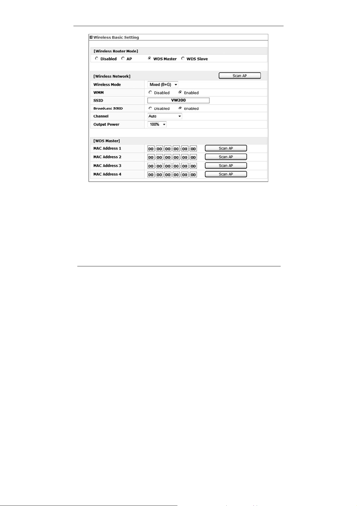
≫ Wireless Distribution System(WDS) Master & Slave
WDS is a system that enables the wireless interconnection of access points in
network. It allows a wireless network to be expanded using multiple access points
without need for a wired backbone to link them. It is possible to extend wireless
coverage area by using more than two VW-200 (Maximum 4).
WDS can be either a WDS master or remote WDS slave. WDS Master relays data
between remote WDS slave, wireless clients or other relay station to either a main or
other relay WDS slave. WDS Master & Slave must be configured as same SSID,
Channel and security.
Note : When you setup WDS function, please disable wireless security options of every AP’s.
WDS function of VW200 series is applicable with other APs which use Ralink chipset but function can
be restricted for other wireless chipset.
¾ Setting Wi-Fi security : Disable Wi-Fi security option in each units.
(You can set security option in WDS mode but recommend to set security
after WDS configuration. Also you should set same security option in each
Master and Slave unit.)
¾ WDS Master Setting : Master mode should be set in the unit which is working
with EVDO network for WAN.
Connect to WEB UI using IP address, “192.168.200.1”.
Go to [Advanced Set up] -> [Wireless Set up] -> [Basic setting].
Click [WDS Master] -> Set desired SSID and Channel.
(These SSID and Channel should be same with WDS slave device.)
Click “Scan AP” in WDS Master section -> Choose AP that you want to use
as WDS Slave -> Click “Apply” to apply your configuration.
¾ WDS Slave Setting : Connect to WEB UI using IP address, “192.168.200.1”
which you want to use as WDS slave.
Go to [Advanced Set up] -> [Wireless Set up] -> [Basic setting].
Click [WDS Slave] Æ Set desired SSID and Channel.
(These SSID and Channel should be same with WDS Master device.)
Set desired IP address of WEB UI.
(Once device is operated as WDS slave, you can access WEB UI via this
address.)
Click “Scan AP” in WDS Slave section -> Choose AP that you want to use as
WDS Master -> Click “Apply” to apply your configuration.
16
Page 18
Section 3 – Configuration
17
Page 19
Section 3 – Configuration
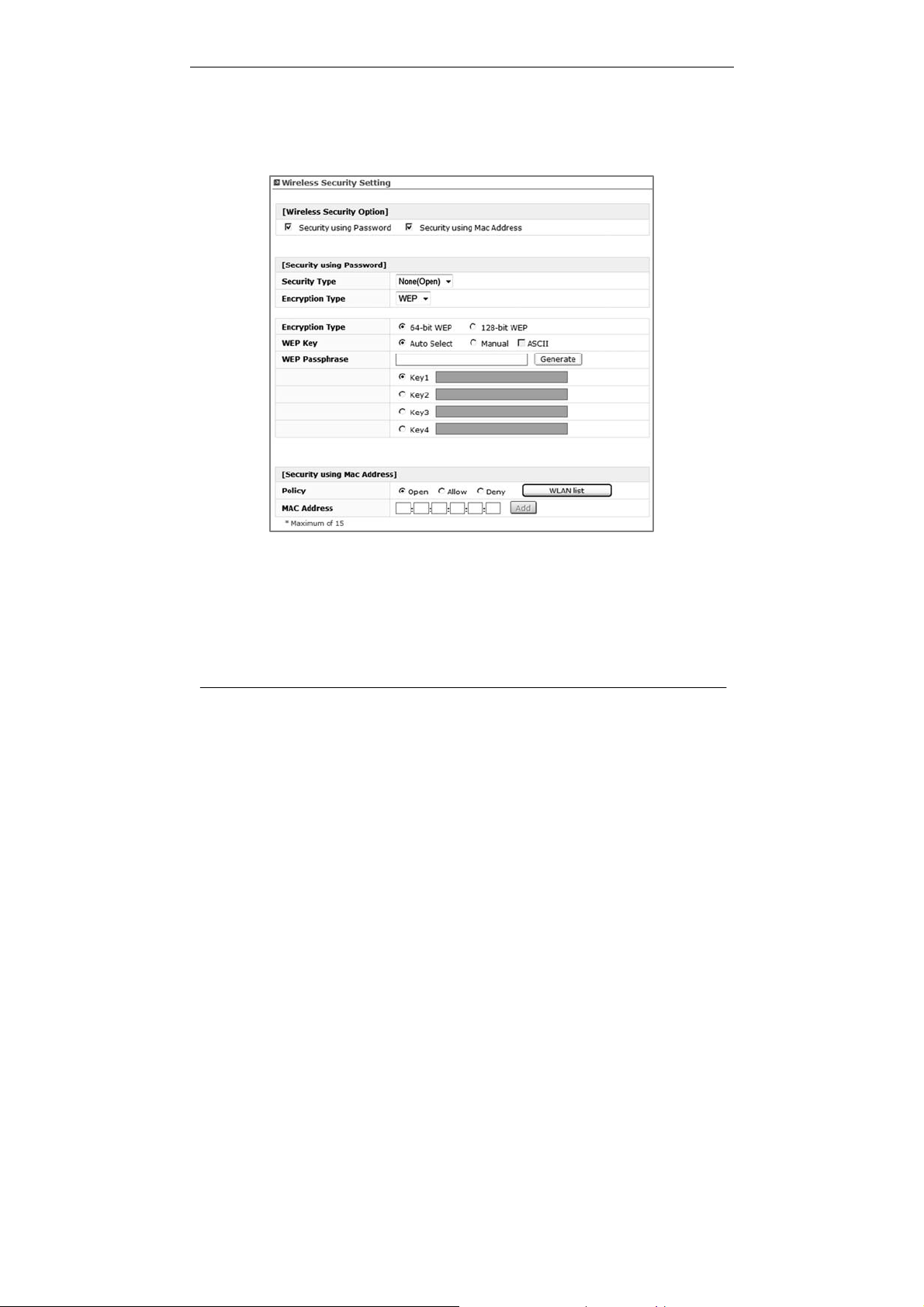
≫ Wireless Security Setting
Here are a few different ways you can maximize the security of your wireless
network and protect your data from prying eyes and ears. This section is intended
for the home, home office, and small office user. At the time of this User Manua l’s
publication, there are two encryption methods available.
Security Using Password
Security Type : Select a Security Type from drop-down menu.
¾ None(open) & Shared – In this mode, a wireless device must know the
WEP key to join the network.
¾ WPA-PSK & WPA-PSK2 - In this mode, Wi-Fi protected access with Pre-
Shared Key (WPA-PSK and WPA-PSK2) data encryption provides
extremely strong data security, very effectively blocking eaves dropping.
18
Page 20

Section 3 – Configuration
Uses a pass phrase or key to authenticate your wireless connection.
The key is an alpha-numeric password between 8 and 63 characters long.
The password can include symbols and spaces.
Encryption Type : Select an Encryption Type from drop-down menu
¾ None(open) & Shared
¾ WEP (Wired Equivalent Privacy) - WEP provides security by encrypting
data over your wireless network so that it its protected as it is transmitted
from one wireless device to another. To gain access to a WEP network, you
must know the key. The key is a string of characters that you create. When
using WEP, you must determine the level of encryption. The type of
encryption determines the key length. In this mode, this is a common
protocol that adds security to all Wi-Fi compliant wireless products. WEP
was designed to give wireless networks the equivalent level of privacy
protection as a comparable wired network.
¾ WPA-PSK & WPA-PSK2.
¾ TKIP & AES - Improved data encryption through the Temporal Key Integrity
Protocol(TKIP). TKIP scrambles the keys using a hashing algorithm and, by
adding an integrity-checking feature, ensures that the keys haven’t been
tampered with. WPA2 is based on 802.11i and uses Advanced Encryption
Standard(AES) instead of TKIP.
Security using Mac Address
The MAC address security is a powerful security feature that allows you to specify
which computers are allowed on the network. When you use this feature, you must
enter the MAC address of each client (computer) on your network to allow network
access to each.
Policy : Select a Policy from the three different modes:
¾ Open – In this mode, there is no restriction to any device connected to
the Modem whether it is through Wi-Fi or Ethernet ports.
¾ Deny – In this mode, the service table shows the client \ MAC address
being blocked by the Modem.
¾ Allow – In this mode, the service table shows the client MAC address
allowed by the Modem.
Note: You will not be able to delete the MAC address of the computer you are using to access the Router’s
administrative functions (the computer you are using now).
19
Page 21
Section 3 – Configuration
Traffic Contr o l
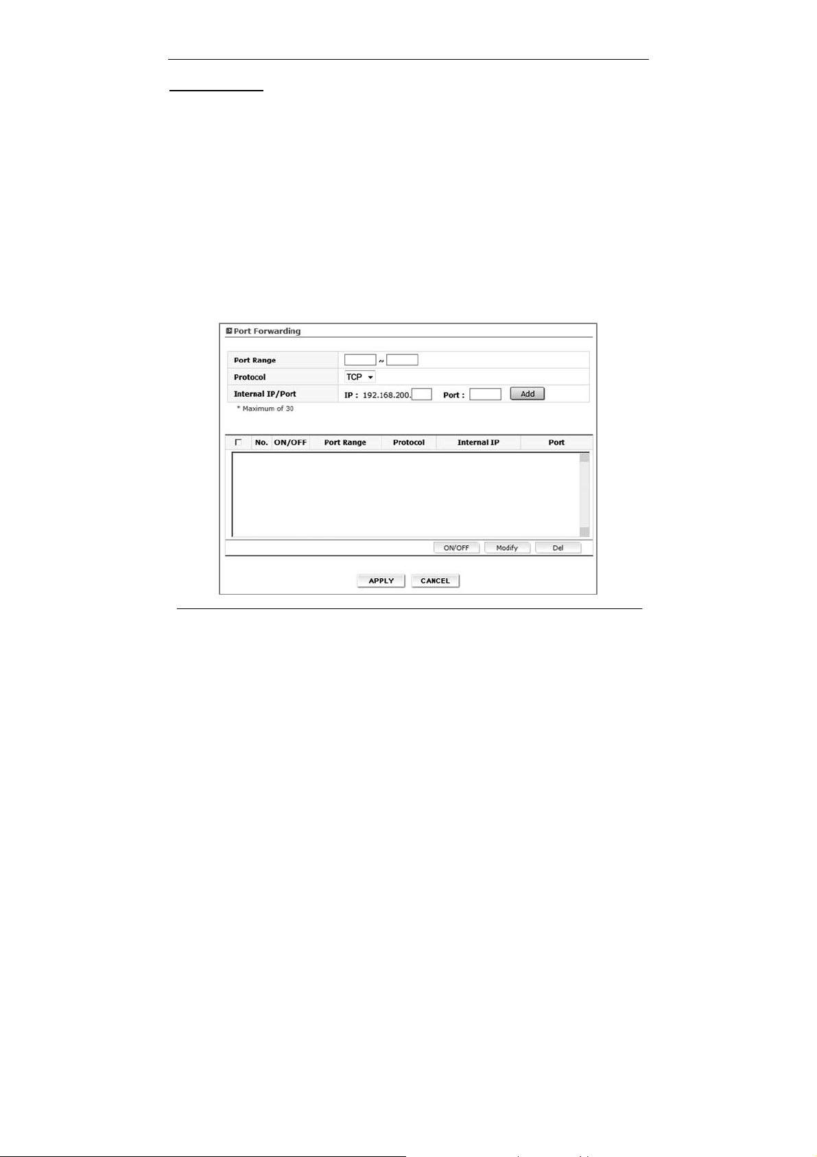
≫Port Forwarding
Using the port forwarding feature, you can allow certain types of incoming traffic to
reach servers on your local network. For example, you might make a local Web
server, FRTP server visible and available to the Internet. Clicking on the header of
the “Port Forwarding” tab will take you to the “Port Forwarding” header page. This
function will allow you to route external (Internet) calls for services such as a web
server (port 80), FTP server (Port 21), or other applications through your Router to
your internal network. You will need to contact the application vendor to find out
which port settings you need. To enter settings, select the Protocol from the
dropdown box, you will see a list of common applications (TCP,UCP). Select the
desired applications, enter the IP address and the port number in the space
provided for the internal (server) machine and click “Add” & “Apply”.
20
Page 22

Section 3 – Configuration
≫Demilitarized Zone (DMZ)
The DMZ feature is helpful when you using some on line WEB, FTP, Telnet, E-Mail
conferencing application. The modem is programmed to recognize some of these
applications and to work correctly with them, but there are other applications that
might not function well. Incoming traffic from the internet is usually discarded by
the modem unless the traffic is a response to one of your local computers. The
computer in the DMZ is NOT protected from hacker attacks.
≫Irregular FTP
You can use this function if you wish to connect to external irregular FTP port. You
can use maximum of five irregular FTP port.
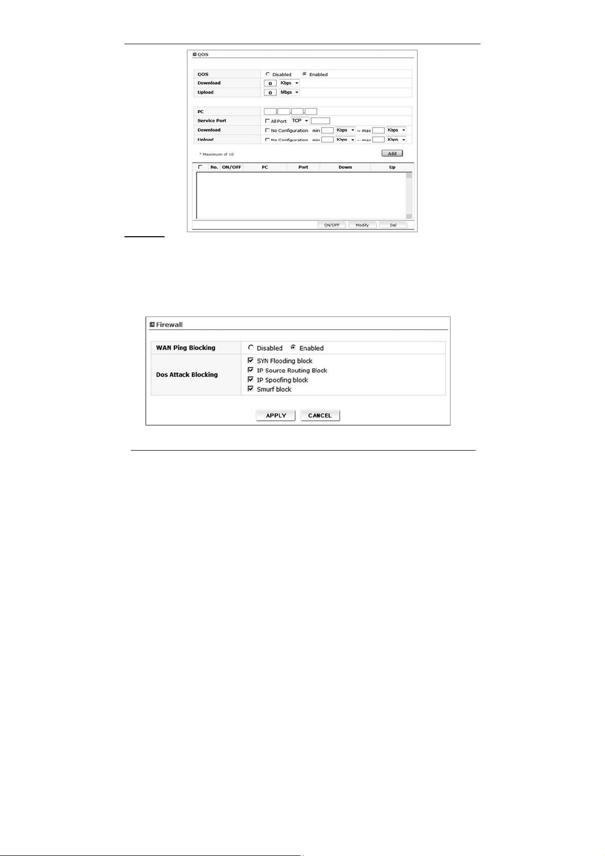
≫Quality of Service (QOS)
The QOS Engine option helps improve your network performance by prioritizing
applications. By default the QOS Engine are disabled and application priori ty is not
classified automatically. It guarantees the minimum speed by setting either pc or
port speed and it also limits the maximum speed. It is efficient use this function
when you have many users. It is only possible to manage setting for 10 pc
.
Download, Upload: It is current speed of CDMA service. It is possible to
manage the speed of the internet between 12kbs and
65Mbps.
PC: When using a service to limit the speed of the internet
connection, and you have many PCs connected to one
router, then the speed of the internet slow down.
Service Port : You need to assign a unique port number to insure that
you have the min speed required.
Download, Upload speed: The speed at which data can be transferred from the
modem. You can limit the speed for both min & max.
21
Page 23
Section 3 – Configuration
Security
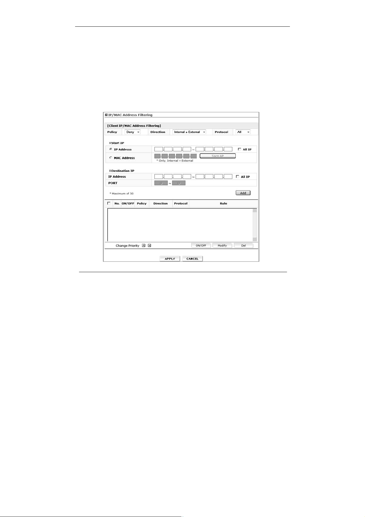
≫ Firewall
Your Router is equipped with a firewall that will protect your network from a wide
array of common hacker attacks including:
WAN Ping / SYN Flooding / IP Source Routing / IP Spoofing / Smurf Attack
22
Page 24
Section 3 – Configuration
You can turn the firewall functions off if needed. Turning off the firewall protection
will not leave your network completely vulnerable to hacker attacks, but it is
recommended that you turn the firewall on whenever possible.
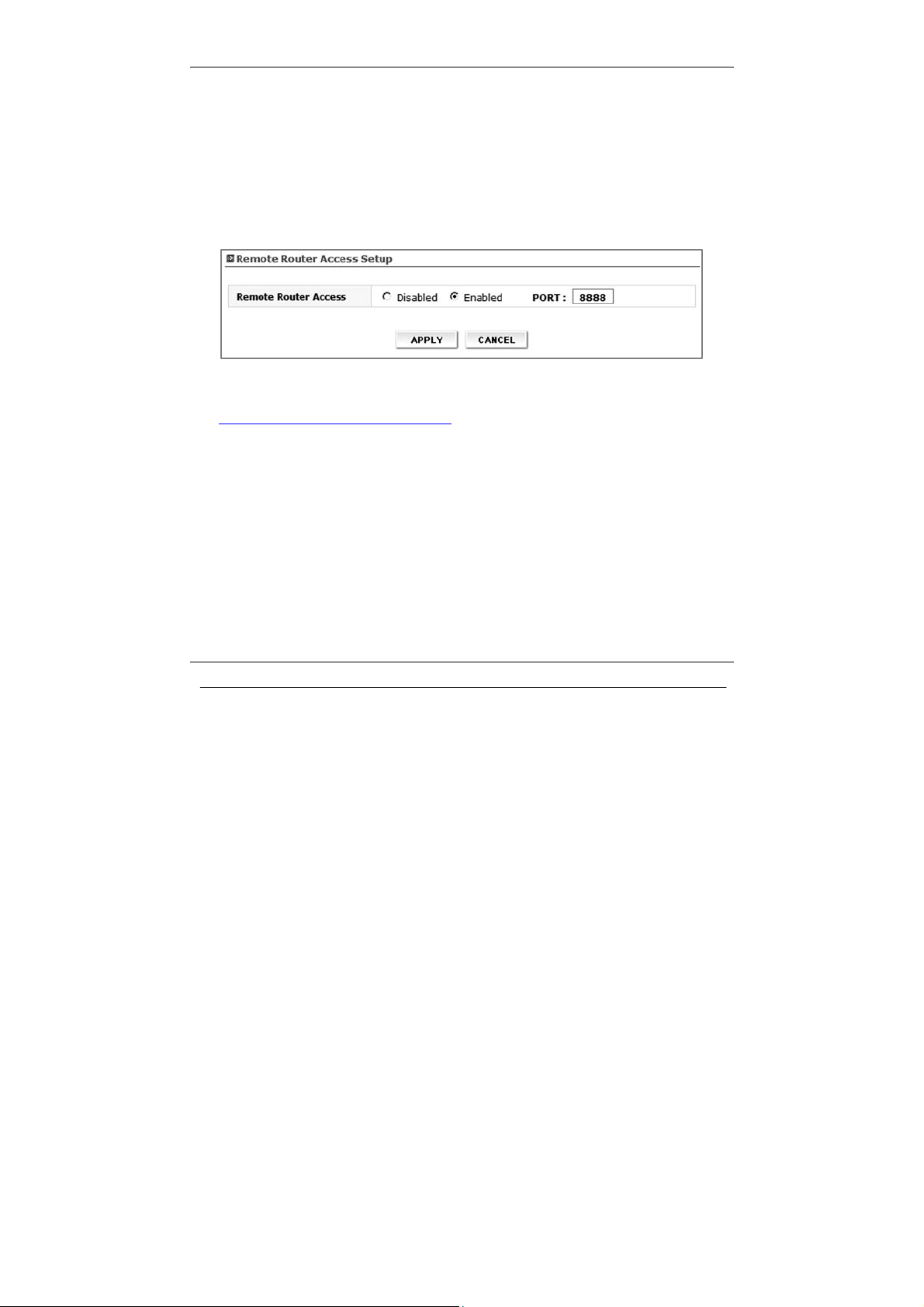
≫ IP/MAC Address Filtering
The Router can be configured to restrict access to the Internet, email, or other
network services at specific days and times. Restriction can be set for a single
computer, a range of computers, or multiple computers by IP or MAC address
specification. Available up to 30ea configuration list.
23
Page 25

Section 3 – Configuration
[Client IP/MAC Address Filtering]
Policy : Select filtering policy Deny or Allow
Direction
¾ Internal to External: Select if you want to apply filtering policy in the
outgoing communication. (All clients are allowed in case of outgoing
communication by default)
¾ External to Internal: Select if you want to apply filtering policy in the
incoming communication. (All clients are restricted in case of incoming
communication by default. Hence this option is valid in case of DMZ or IP
Forwarding)
Protocol : Select one among of TCP / UDP / ALL. If you select ALL option, filtering
policy will be applied in all protocol.
Start IP
Internal to External
¾ IP Address : Configure internal client IP address to be restricted by
filtering policy.
¾ All IP: Apply filtering policy in all clients.
¾ MAC Address: Configure internal client MAC address to be restricted by
filtering policy. You can scan client MAC address using
Scan AP button.
External to Internal
¾ IP Address: Configure external IP address to be restricted by filtering
policy.
¾ All IP: Apply filtering policy in all external IP address.
¾ MAC Address: Not available in this option.
Destination IP
Internal to External
¾ IP Address/PORT: Configure external IP address and Port to be restricted.
¾ All IP : Apply filtering in all external IP address.
External to Internal
¾ IP Address/PORT: Configure internal client IP address and Port to be
24
Page 26
Section 3 – Configuration
restricted.
¾ All IP: Apply filtering in all internal client IP address.
≫ URL Filtering
You can block desired website URL. Once you register specified URL, clients can
not access this address. Available up to 10 URL registrations.
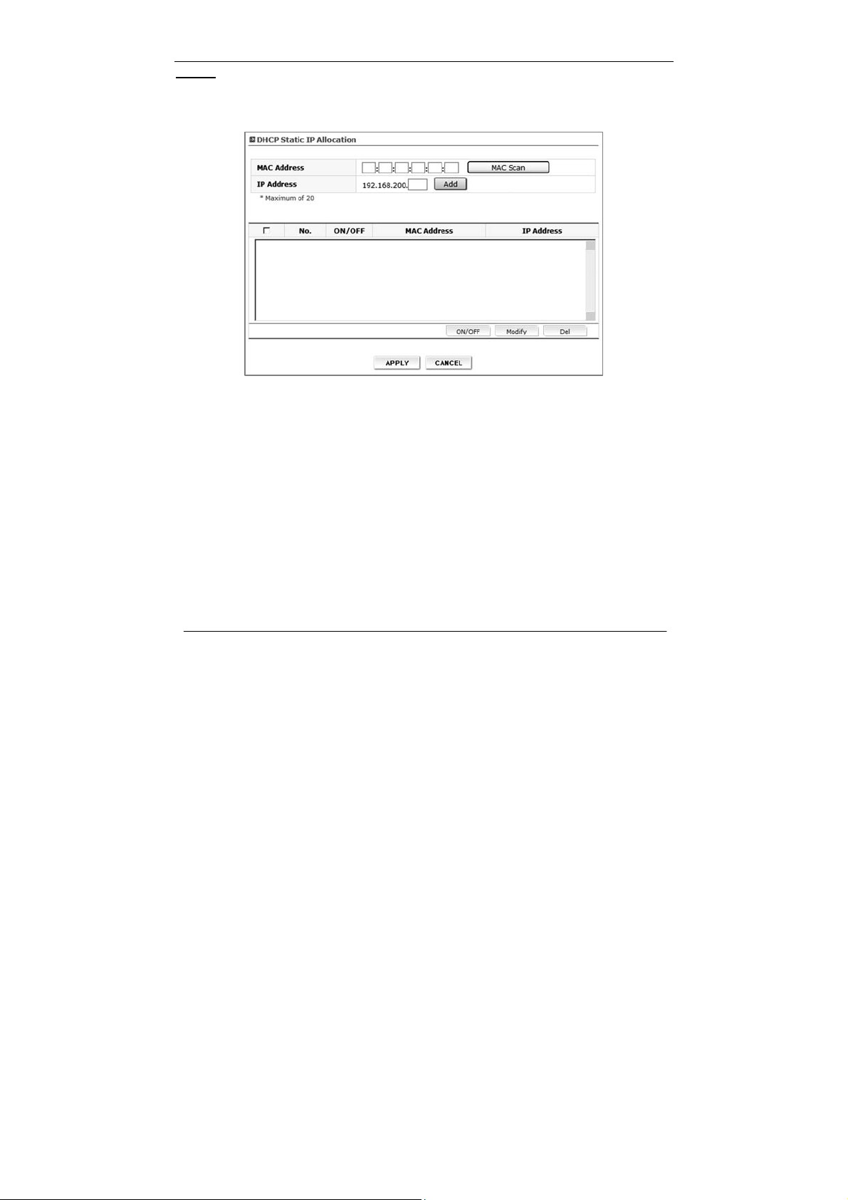
≫ Remote Router Access
Remote management allows you to make changes to your Router’s settings from
anywhere on the Internet.
Ex) If registered DDNS Domain name is “vertexwireless.vw200.com” and you have set
port number “8888” in this menu, you can access the router with this address,
http://vertexwireless.vw200.com:8888
.
25
Page 27
Section 3 – Configuration
Utility
≫ DHCP Static IP Allocation
Use this menu if you want to assign a fixed local IP address to a MAC address.
¾ MAC Address: Enter MAC address in the “MAC Address” field that you
want to assign fixed IP address. Or you can use MAC
address scan function.
If you press “MAC Scan” button, router will search
currently connected client’s MAC address and list up in
the table.
¾ IP Address: Select one MAC address of the list and enter the IP
address you want to it to have in the “IP Address” field
and press “Add” to add static IP allocation information in
the table.
Make sure the IP address is between the starting DHCP
server’s IP address and maximum number of DHCP
users range.
A list of DHCP clients and their fixed local IP address will be displayed at the bottom
of the screen. If you want to remove a client from the list, click “Del”.
26
Page 28
Section 3 – Configuration
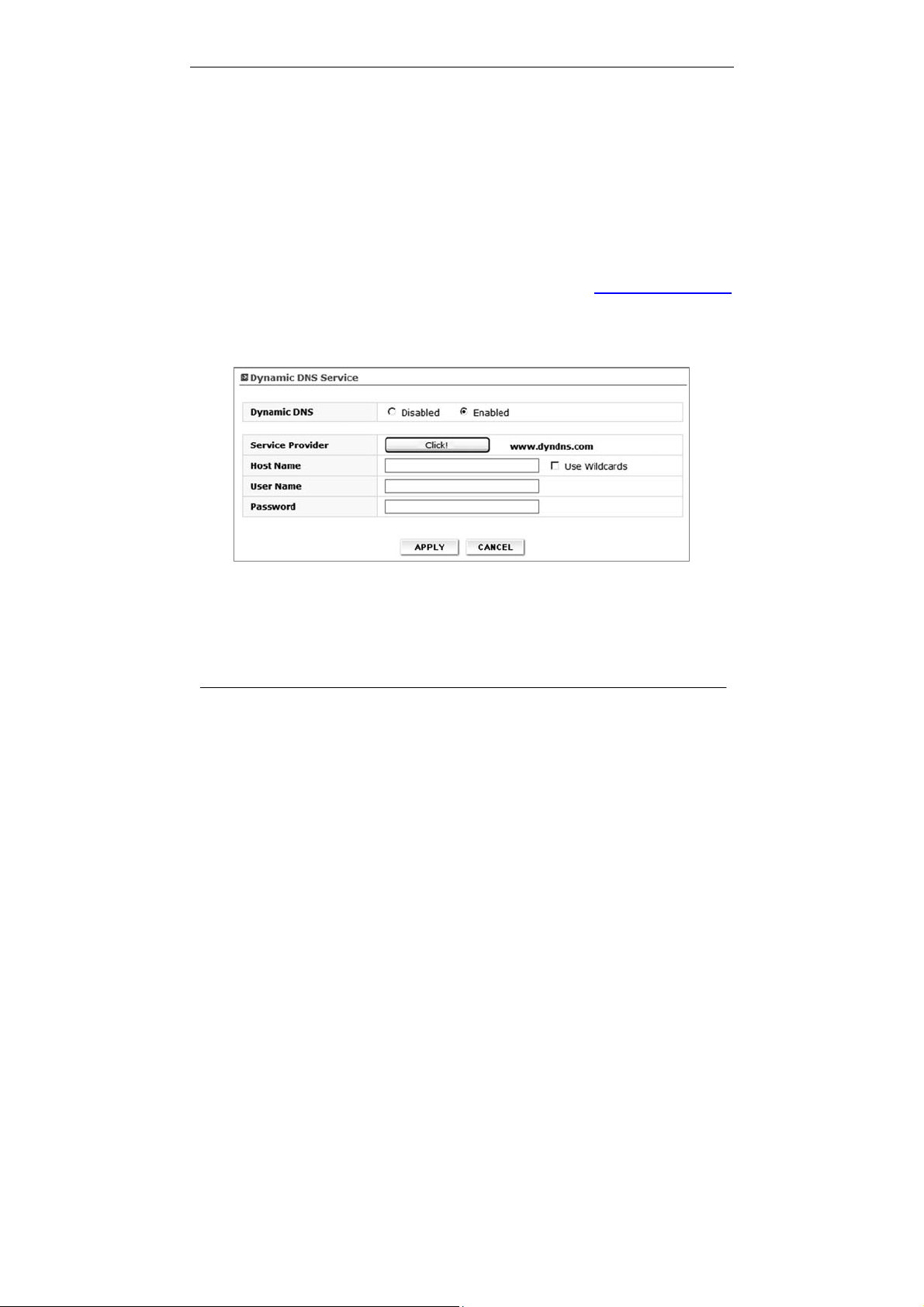
≫ DDNS
The Dynamic DNS service allows you to alias a dynamic IP address to a static host
name in any of the many domains DynDNS.org offers, allowing your network
computers to be more easily accessed from various locations on the Internet.
DynDNS.org provides this service, for up to five host names, free to the Internet
community. The Dynamic DNSSM service is ideal for a home website, file server, or to
make it easy to access your home PC and stored files while you’re at work. Using the
service can ensure that your host name always points to your IP address, no matter
how often your ISP changes it. When your IP address changes, your friends and
associates can always locate you by visiting yourname.dyndns.org instead.
To register free for your Dynamic DNS host name, please visit http://www.dyndns.org
z Setting up the Router’s Dynamic DNS updat e client
You must register with DynDNS.org’s free update service before using this feature.
Once you have your registration, follow the directions below.
.
¾ Select “Enabled” to activate DDNS service.
¾ Press “Click” button to connect DynDNS.org’s web site.
¾ Enter the DynDNS.org domain name you set up with DynDNS.org in the
“Host Name” field
¾ Wildcards option: This setting enables or disables wildcards for your host.
27
Page 29

Section 3 – Configuration
¾ For example, if your DDNS address is vw200.dyndns.org and you enable
wildcards, then x.vw200.dyndns.org will wor k as well (x is the wildcard).
¾ To enable wildcards, select “Use Wildcards” option.
¾ Enter your DynDNS.org user name in the “User Name” field
¾ Enter your DynDNS.org password in the “Password” field
¾ Press “APPLY” to update your IP address
Whenever your IP address assigned by your ISP changes, the Router will
automatically update DynDNS.org’s servers with your new IP address. You can also
do this manually by clicking the “APPLY” button.
≫ UPnP
Universal Plug and Play (UPnP) is a technology that offers seamless operation of
voice messaging, video messaging, games, and other applications that are UPnPcompliant. Some applications require the Router ’s firewall to be configured in a
specific way to operate properly. This usually requires opening TCP and UDP ports.
An application that is UPnP-compliant has the ability to communicate with the Router,
basically “telling” the Router which way it needs the firewall configured. The Router
ships with the UPnP feature disabled. If you are using any applications that are
UPnP-compliant, and wish to take advantage of the UPnP features, you can enable
the UPnP feature. Simply select “Enabled” in the “UPnP” section of the “Utility” page.
Click “APPLY” to save the change.
≫ NAT-T
If you are using VPN, VoIP or PPTP service you can enable or disable depending on
your network environment.
≫ Wake on LAN
Wake on LAN (WOL) is an Ethernet computer networking standard that allows a
computer to be turned on or woken up remotely by a network message. WOL must
be enabled in the Power Management section of a PC motherboard's BIOS. It may
also be necessary to configure the computer to reserve power for the network card
when the system is shutdown.
28
Page 30
Section 3 – Configuration
Press “MAC Scan” button to scan MAC address of currently connected client PC
through RJ45 and select the scanned MAC address.
Now you connect to the router, access WEB UI and press ON button. Then the client
PC will be turned on remotely using WOL.
This is useful function with DDNS when you need to turn on the client remotely.
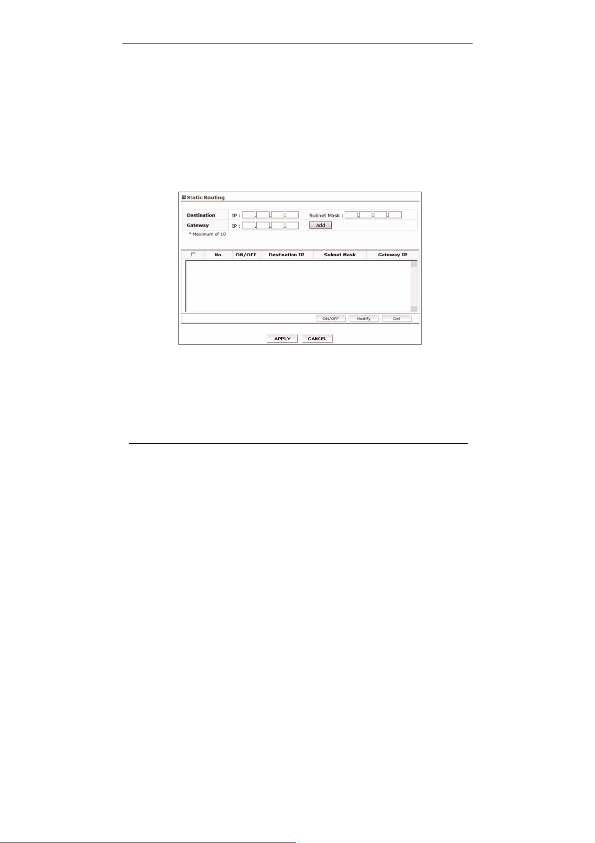
≫ Static Routing
A static IP address connection type is less common than other connection types.
This is pre-determined pathway that network information must travel to reach a
specific host or network.
If your ISP uses static IP addressing, you will need your IP address, subnet mask,
and ISP gateway address. This information is available from your ISP or on the
paperwork that your ISP left with you.
Destination: The Destination is LAN IP address of the remote network
or host to which you want to assign a static route.
Subnet Mask: T his determines which portion of a Destination LAN IP
address is the network portion, and which portion is the
host portion.
Gateway: This is the IP address of the gateway device that allows
29
Page 31

Section 3 – Configuration
for contact between the Router and the remote network
or host. A list of Static Routing table will be displayed at
the bottom of the screen. If you want to remove a client
from the list, click “Del”.
30
Page 32
Section 4 – Administration
Administrator
≫ Login Password
This menu is for setting up WEB UI login password.
The Router ships with NO password entered. If you wish to add a password for
greater security, you can set a password here. Write down your password and keep it
in a safe place, as you will need it if you need to log into the Router in the future. It is
also recommended that you set a password if you plan to use the remote
management feature of your Router.
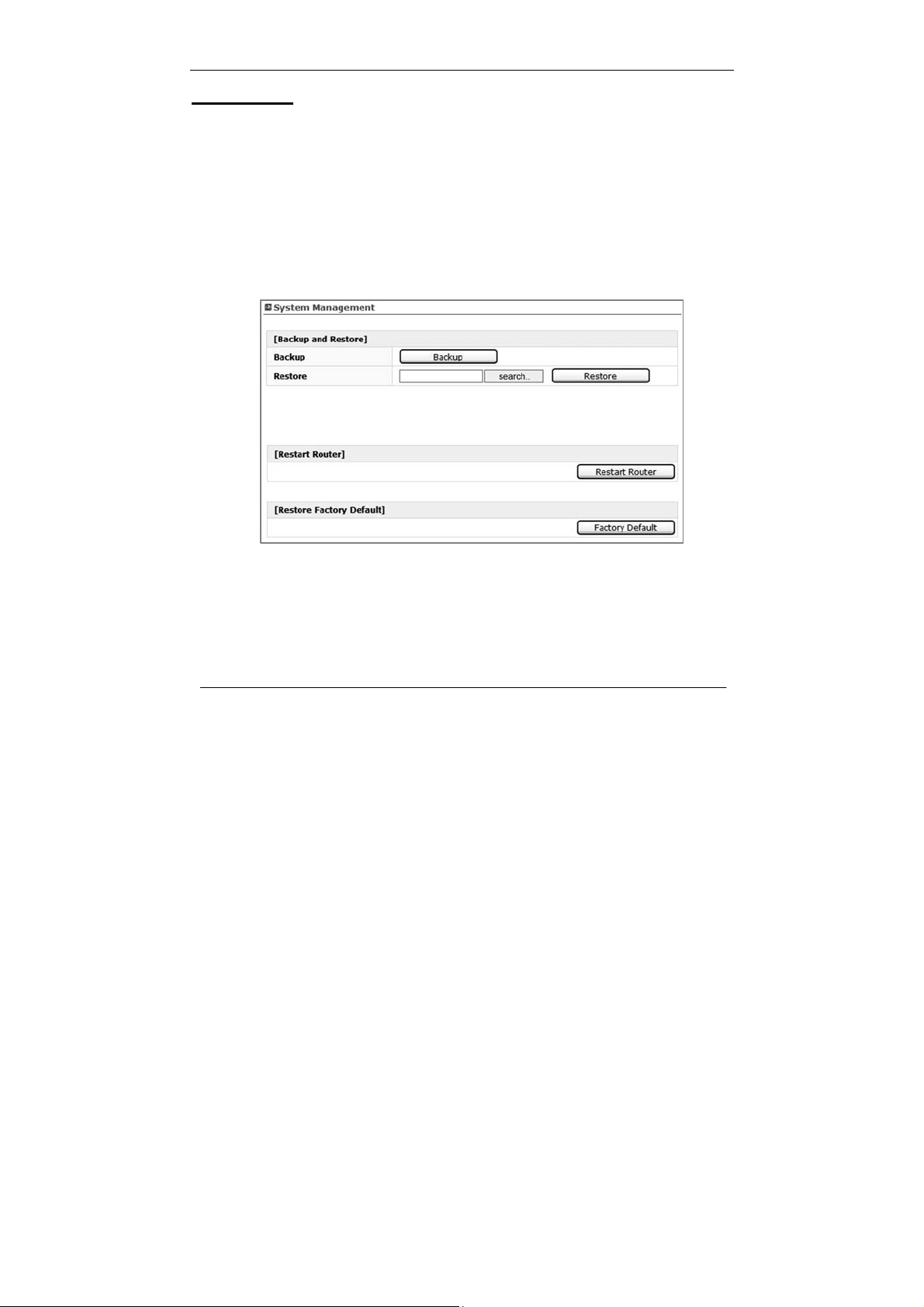
≫ System Management
≫ Backup and Restore
You can save your current configuration or restore a previously saved configuration
by using this feature. Saving your configuration will allow you to restore it later if your
settings are lost or changed. It is recommended that you back up your current
configuration before performing a firmware update.
31
Page 33

Section 4 – Administration
≫ Restart Router
Sometimes it may be necessary to restart or reboot the Router if it begins working
improperly. Restarting or rebooting the Router will NOT delete any of your
configuration settings.
≫ Restore Factory Default
Using this option will restore all of the settings in the Router to the factory (default)
settings. It is recommended that you back up your settings before you restore all of
the defaults.
≫ Firmware Upgrade
From time to time, your service provider may release new versions of the Router’s
firmware.
Firmware updates contain feature improvements and fixes to problems that may exist.
When service provider releases new firmware, you can download the firmware from
the service provider update website and update your Router’s firmware to the latest
version. In the “Firmware upgrade” page, click “Browse”. A window will open that
allows you to select the location of the firmware update file. A warning will be
displayed while upgrading is progressed, ple ase follow the instruction.
32
Page 34

Section 5 – Status
Status
≫ Status Information
You can check current gateway connection status via this menu. Detailed WAN /
LAN / WLAN descriptions can be seen here.
≫ DHCP Allocation Information
You can view a list of the computers (known as clients), which are connected to
your network. You are able to view the IP address of the computer, the host name (if
the computer has been assigned on), and the MAC address of the computer’s
network interface card.
≫ Traffic Information
A Router keeps statistics of traffic that passes through it. You are able to view the
amount of packets that pass through the Ethernet and wireless portions of the
network. Using Refresh button, you can reset all packet volume.
≫ System Log
This menu displays router system log and you can save this as text file using Save
button. If you want to update or reset system log, press Refresh or Delete button.
33
Page 35

Section 6 – Troubleshooting
Troubleshooting
1. I am not able to access the web-based configuration utility
- Verify physical connectivity by checking for solid link lights on the device. If
you do not get a solid link light, try using a different cable on the device.
- Disable any internet security software running on the computer.
- Make sure you have an updated Java-enabled web browser. Recommend the
following:
Internet Explorer 6.0 or higher
Firefox 1.5 or higher
Netscape 8 or higher
Mozilla 1.7.12 (5.0) or higher
Opera 8.5 or higher
Safari 1.2 or higher (with Java 1.3.1 or higher)
2. I forgot my password.
- Need to reset your router. Unfortunately this process will change all your
settings back to the factory defaults.
To reset the router, hold the reset button for 10 seconds (reset button is placed
at the bottom of the router). Release the button and the router will go through
its reboot process then wait for 30 seconds to access the router. The default
IP address is 192.168.200.1. (login password: leave as a blank box)
3. I am not able to connect to certain sites or send and receive emails when
connecting through my router.
- Suggest lowering the MTU in increments of ten (ex. 1492, 1482, 1472, etc)
4. I need to update the firmware
- First of all, prepare proper F/W to be downloaded into the router (it will be
provided by Service provider if needed) and go to “Firmware upgrade” page
under Administrator in Web-UI.
34
Page 36

Notice
OEM integrators and installers are instructed that the phrase. This device contains
transmitter FCC ID:
XAVVW240 must be placed on the outside of the host.
Warning: Exposure to Radio Frequency Radiation The radiated output
power of this device is far below the FCC radio frequency exposure
limits. Nevertheless, the device should be used in such a manner that
the potential for human contact during normal operation is minimized.
In order to avoid the possibility of exceeding the FCC radio
frequency exposure limits, human proximity to the antenna should
not be less than 20cm during normal operation. The gain of the
antenna for Cellular band must not exceed
1.630 dBi.
The gain of the antenna for PCS band must not exce
ed 0.00000dBi.
Page 37

INFORMATION TO THE USER
"Changes or modifications not expressly approved by Vertex Wireless could void the user's
authority to operate the equipment".
"NOTE: This equipment has been tested and found to comply with the limits for a Class
B digital device, pursuant to part 15 of the FCC Rules. These limits are designed to provide
reasonable protection against harmful interference in a residential installation.
This equipment generates, uses and can radiate radio frequency energy and, if not installed
and used in accordance with the instructions, may cause harmful interference
to radio communications. However, there is no guarantee that interference will not occur
in a particular installation. If this equipment does cause harmful interference to
radio or television reception, which can be determined by turning the equipment off and
on, the user is encouraged to try to correct the interference by one or more of the following
measures:
-Reorient or relocate the receiving antenna.
-Increase the separation between the equipment and receiver.
-Connect the equipment into an outlet on a circuit different from that to which the receiver is
connected.
-Consult the dealer or an experienced radio/TV technician for help.”
FCC Compliance Information
This device complies with Part 15 of FCC Rules.
Operation is subject to the following two conditions:
(1) This device may not cause harmful interference, and
(2) This device must accept any interference received.
Including interference that may cause undesired operation.
Page 38

37
 Loading...