

50/144/430 MHz
TRIPLE-BAND HEAVY DUTY
SUBMERSIBLE TRANSCEIVER
VX-8R
OPERATING MANUAL
VERTEX STANDARD CO., LTD.
4-8-8 Nakameguro, Meguro-Ku, Tokyo 153-8644, Japan
VERTEX STANDARD
US Headquarters
10900 Walker Street, Cypress, CA 90630, U.S.A.
YAESU EUROPE B.V.
P.O. Box 75525, 1118 ZN Schiphol, The Netherlands
YAESU UK LTD.
Unit 12, Sun Valley Business Park, Winnall Close
Winchester, Hampshire, SO23 0LB, U.K.
VERTEX STANDARD HK LTD.
Unit 5, 20/F., Seaview Centre, 139-141 Hoi Bun Road,
Kwun Tong, Kowloon, Hong Kong
VERTEX STANDARD (AUSTRALIA) PTY., LTD.
Normanby Business Park, Unit 14/45 Normanby Road
Notting Hill 3168, Victoria, Australia

Contents
Introduction ................................................................................. 1
Controls &Connections ............................................................... 2
Display Icons & Indicators ......................................................... 3
Keypad Functions ....................................................................... 4
Accessories & Option .................................................................. 6
Accessories Supplied with the VX-8R ..................................... 6
Available Options for your VX-8R .......................................... 7
Installation of Accessories ........................................................... 8
Antenna Installation ................................................................. 8
Belt Clip Installation ................................................................ 8
Installation of FNB-101LI Battery Pack .................................. 9
Battery Life Information ........................................................ 10
Installation of FBA-39 Alkaline Battery Case ....................... 11
Interface of Packet TNCs .......................................................... 12
Operation ................................................................................... 13
Switching Power On and Off ................................................. 13
Adjusting the Volume Level .................................................. 13
Squelch Adjustment ............................................................... 14
Selecting the Operating Band ................................................ 15
Selecting the Frequency Band ................................................ 16
Frequency Navigation ............................................................ 17
1) Tuning Dial .................................................................. 17
2) Direct Keypad Frequency Entry .................................. 17
3) Scanning ....................................................................... 18
Transmission .......................................................................... 19
Changing the Transmitter Power Level ............................ 19
VOX Operation ................................................................ 20
AM and FM Broadcast Reception ......................................... 22
AF-Dual Operation ........................................................... 24
Advanced Operation ................................................................. 26
Keyboard Locking ................................................................. 26
Adjusting the Keypad Beeper Volume Level ......................... 27
Setting the Frequency Display Image Size ............................. 27
Audio Muting ......................................................................... 28
Keypad/LCD Illumination ...................................................... 28
Changing the Channel Steps .................................................. 29
Changing the Receiving Mode ............................................... 29
SQL S-meter .......................................................................... 30
Repeater Operation ................................................................... 31
General ................................................................................... 31
Repeater Shifts ....................................................................... 31
Automatic Repeater Shift (ARS) ........................................... 31
Manual Repeater Shift Activation .......................................... 32
Changing the Default Repeater Shifts .............................. 32
Checking the Repeater Uplink (Input) Frequency ................. 33
CTCSS/DCS/EPCS Operation ................................................. 34
CTCSS Operation .................................................................. 34
DCS Operation ...................................................................... 36
DCS Code Inversion ........................................................ 37
Tone Search Scanning ........................................................... 39
EPCS (Enhanced Paging & Code Squelch) ........................... 40
Storing the CTCSS Tone Pairs for EPCS Operation ....... 40
Activating the Enhanced Paging & Code Squelch System .. 41
Paging Answer Back ........................................................ 41
CTCSS/DCS/EPCS Bell Operation ....................................... 42
Programming the User Melody ........................................ 43
Split Tone Operation .............................................................. 44
Tone Calling (1750 Hz) ......................................................... 45
Memory Mode (Regular Memory Channel Operation) ......... 46
Memory Storage .................................................................... 47
Memory Recall ....................................................................... 48
HOME Channel Memory ....................................................... 49
Labeling Memories ................................................................ 50
Memory Offset Tuning .......................................................... 51
Masking Memories ................................................................ 52
Memory Bank Operation ....................................................... 53
Moving Memory Data to the VFO ........................................ 55
Memory Only Mode ............................................................... 55
Memory Mode (Special Memory Channel Operation) .......... 56
Weather Broadcast Channels ................................................. 56
VHF Marine Memory Channels ............................................. 57
Short-wave Broadcast Station Memory Channels ................. 58
Scanning ..................................................................................... 60
General ................................................................................... 60
VFO Scanning ........................................................................ 62
How to Skip (Omit) a Frequency during VFO Scan ........ 63
Memory Scanning .................................................................. 64
How to Skip (Omit) a Channel during Memory Scan ...... 65
Preferential Memory Scan ................................................ 66
Memory Bank Scan .......................................................... 67
Programmable (Band Limit) Memory Scan (PMS) ............... 68
“Priority Channel” Scanning (Dual Watch) ........................... 69
Priority Revert Mode ....................................................... 70
Automatic Lamp Illumination on Scan Stop .......................... 71
Band Edge Beeper ................................................................. 71
Bluetooth® Operation ............................................................. 72
Pairing .................................................................................... 72
Activation ............................................................................... 73
Operation ............................................................................... 74
GPS Operation .......................................................................... 76
Setting the Time Zone (Time Offset) ..................................... 78
Selecting the Display Units of the GPS Screen ...................... 79
Selecting the Map Datum ...................................................... 79
APRS® Operation ...................................................................... 80
Preparations ........................................................................... 80
Receiving an APRS Beacon ................................................... 83
Transmit an APRS Beacon .................................................... 85
Receiving an APRS Message ................................................. 88
Transmit an APRS Message .................................................. 90
ARTSTM (Automatic Range Transponder System) ................ 92
Basic ARTSTM Setup and Operation ..................................... 93
ARTSTM Polling Time Options .............................................. 93
ARTSTM Alert Beep Options ................................................. 94
CW Identifier Setup ............................................................... 95
Spectrum Analyzer Operation ................................................. 96
Channel Counter Operation ..................................................... 98
Smart Search Operation ......................................................... 100
Message Feature ...................................................................... 102
General ................................................................................. 102
Programming a Message ...................................................... 102
Programming a Member List ............................................... 103
Set your Personal ID ............................................................ 104
Sending a Message ............................................................... 105
Receiving a Message ............................................................ 106
Emergency Feature ................................................................. 107
Emergency Channel Operation ............................................ 107
Emergency Automatic ID (EAI) feature .............................. 108
Selecting the EAI mode and its Transmit Time .............. 109
Activating the EAI feature ............................................. 109
To Locate an Unresponsive Operator
using the EAI feature .......... 110
Internet Connection Feature .................................................. 111
General ................................................................................. 111
SRG (“Sister Radio Group”) Mode ..................................... 111
FRG (“Friendly Radio Group”) Mode ................................. 112
DTMF Operation ..................................................................... 114
CW Learning Feature ............................................................. 116
CW Training Feature .............................................................. 118
Sensor Mode ............................................................................. 119
Sensor Mode Options .......................................................... 120
Clock Set ........................................................................ 120
Selecting the Measurement Units of the Sensor Unit ..... 121
Correcting the Sensor Unit ............................................. 121
Miscellaneous Setting .............................................................. 122
Password .............................................................................. 122
Programming the [Internet(TXPO)] Key ............................. 123
ATT (Front End Attenuator) ............................................... 124
Receive Battery Saver Setup ............................................... 125
TX Battery Saver ................................................................. 125
Disabling the BUSY Indicator ............................................. 126
Automatic Power-Off (APO Feature) .................................. 126
Transmitter Time-Out Timer (TOT) .................................... 127
ON/OFF Preset Timer .......................................................... 128
Busy Channel Lock-Out (BCLO) ........................................ 129
Changing the TX Deviation Level ....................................... 129
Changing the Microphone Gain ........................................... 130
S-and TX Power Meter Symbols ......................................... 130
Display Contrast .................................................................. 131
Display Dimmer ................................................................... 131
My Bands Operation ............................................................ 132
Changing the Status of the [VOL] Key ................................133
Reset Procedures ..................................................................... 134
Cloning ..................................................................................... 135
Set Mode ................................................................................... 136
APRS/GPS Set Mode .............................................................. 161
Specifications ........................................................................... 166
Installation of the BU-1 (Option) ........................................... 168

INTRODUCTION
The Ultra Compact VX-8R (2.4”W x 3.7”H x 0.9”D) is thinner than the previous advanced
model - It is packed with advanced technology and features, designed for outdoor operation. It
is submersible and shockproof! The compact case combines a rugged die-cast chassis with the
clean, tough polycarbonate resin front panel. Its shockproof versatility will allow you to operate the radio in the toughest environments.
The large High-resolution Dot Matrix LCD display provides clear, easy-to-read indication of
both “A” (Main band) and “B” (Sub band) frequencies, the operating mode, and S-meters for
both bands. When you engage the Spectrum Scope function, the high-resolution display will
indicate relative signal strengths of up to ±50 adjacent channels!
The Bluetooth® capabilities, already known and utilized among users and enthusiasts of the
®
FTM-10R/SR, are also available with the VX-8R. The optional Bluetooth
it possible to operate Hands-free with the optional waterproof Bluetooth
(Stereo) or BH-2 (monaural).
The built-in worldwide standard AX.25 Data TNC Modem permits uncomplicated APRS
operation. (Automatic Packet/Position Reporting System: APRS® is a registered trademark of
the APRS Software and Bob Bruninga, WB4APR.) The VX-8R supports APRS
bps data communication on the B band only. You may communicate your location to other
®
stations along with the position, speed and heading displayed on your radio! You and
APRS
®
others will be able to see your APRS
movement on the web! The VX-8R displays the re-
ceived station’s positions, heading directions, messages, distances, icons (43 kinds), weather
information, object, etc. With the list function you may automatically store and recall up to 20
®
messages and the APRS
2 can provide you with your real time APRS
data from up to 40 stations. The optional GPS Antenna Unit FGPS-
®
data. You may also send the information without
the FGPS-2 if you manually input your data in advance.
Unit BU-1 makes
®
headsets BH-1
®
1200/9600
®
An Enhanced Paging and Code Squelch (EPCS) allows you to page a particular station and
only receive calls from that station. A security Password may be set, which will allow you to
turn on and operate the transceiver only after you enter the Password. A convenient key provides access to Vertex Standard's WIRES™ (Wide-Coverage Internet Repeater Enhancement
System). The Emergency Automatic ID (EAI) function can automatically cause your VX-8R
to transmit your callsign and engage your rig’s microphone, even if you are disabled and unable to press the PTT switch. Additional features include: transmit Time-Out Timer (TOT),
Automatic Power-Off (APO), and Automatic Repeater Shift (ARS). Yaesu’s exclusive ARTS
™
(Auto-Range Transponder System) which “beeps” the user when you move out of communications range with another ARTS™ equipped station. There is provision to reduce the TX deviation for use in areas of high channel congestion. The squelch circuit allows adjusting the squelch
to open at a programmable setting of the S-Meter, thus reducing guesswork in setting the
squelch threshold. Provides a completely independent FM/AM broadcast receiver and an internal bar antenna for better AM broadcast reception. Listen to FM broadcasts in stereo with your
stereo headset/earphone!
We appreciate your purchase of the VX-8R, and encourage you to read this manual thoroughly,
and learn about the many exciting features of your thrilling new Yaesu hand-held transceiver!
VX-8R OPERATING MANUAL 1
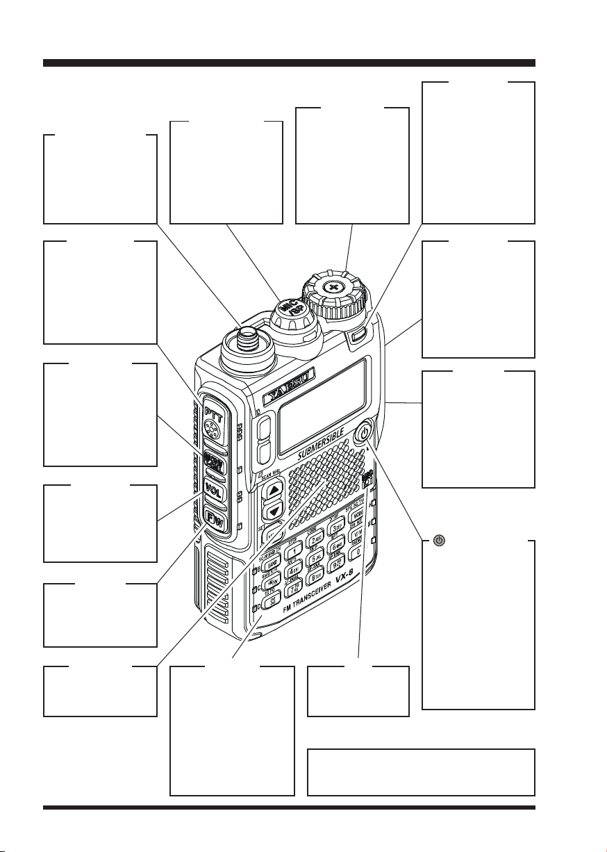
CONTROLS & CONNECTIONS
MIC/SP Jack
ANTENNA Jack
Connect the supplied rubber flex antenna (or another
antenna presenting
a 50-Ohm impedance) here.
This 7-pin miniature jack connects
an optional MH-
74
A7A Speaker Mi-
crophone or CT136 GPS Antenna
Adapter.
DIAL Knob
The main tuning
Dial is used to set
the operating frequency, and is also
used for audio volume level, menu
selections, and
other adjustments.
LED Light
This white LED will
glow (or flash) during “Emergency
Channel” operation. It can also be
useful as a flash
light in a dark environment via the Set
Mode Item 50 LED
LIGHT.
PTT Switch
(“Push To Talk”)
Press this switch inward to transmit,
and release it (to
receive) after your
transmission is
completed.
MONI Key
Pressing this key
disables the noise
squelching action,
allowing you to
hear very weak signals near the background noise level.
VOL Key
Rotate the DIAL
knob while pressing and holding this
key to adjust the
audio volume level.
F/W Key
Pressing this key
activates the “Alternate” key function
of the keypad.
SPEAKER
The internal
speaker is located
hear.
KEYPAD
The 20 front panel
key buttons select
many of the most important operating features.
The functions of the
keys are described in
details on pages 4
and 5.
EAR Jack
This 3-contact miniature jack allows
connection of stereo earphones
With aftermarket
earphones, you
may enjoy stereo
FM broadcasts.
EXT DC
This coaxial DC
jack allows connection to an external
DC power source
(10-16V DC). The
center pin of this
jack is the Positive
(+) line.
(
PWR) Switch
Press and hold this
switch for 2 seconds to toggle the
transceiver’s power
“on” and “off”.
Press this switch
briefly while the
transceiver is
MIC
The internal microphone is located hear.
Ú Some stereo earphone plugs may not
fit this jack, depending on the shape of
the connection plug.
turned “on” to
toggle the key lockout feature “on” or
“off”.
Ú
.
VX-8R OPERATING MANUAL2
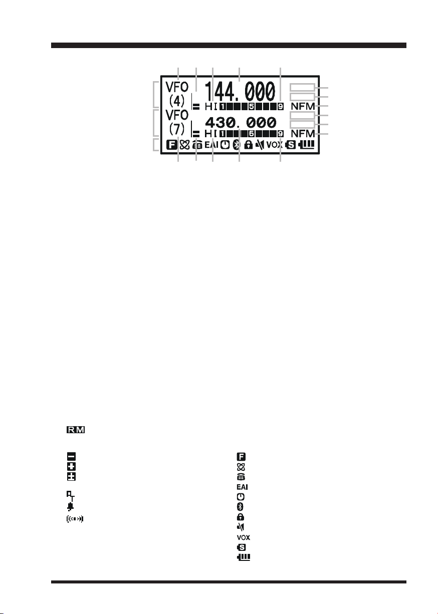
DISPLAY ICONS & INDICATORS
cdef g
“A” Band
Display
“B” Band
Display
Icon
edcfg
FREQUENCY CONTROL
c
VFO: VFO Mode
MR: Memory Mode
MT: Memory Tune Mode
HOM: Home Channel Memory
PMS: Programmable Memory Scan Mode
VDW: Dual Watch Active
(VFO-Memory Channel)
MDW: Dual Watch Active
(Memory Channel-Memory Channel)
SQUELCH TYPE & RADIO MODE
h
TN: Tone Encoder Active
TSQ: Tone Squelch Active
DCS: Digital Code Squelch Active
RTN: Reverse Tone Squelch Active
PR: User Programmed Reverse CTCSS Decoder Active
PAG : Enhanced Paging & Code Squelch (EPCS) Active
MSG: Message Feature Active
DC: Split Tone Feature Active (DCS Encode only)
T-D: Split Tone Feature Active (Encodes a CTCSS Tone and Decodes a DCS Code)
D-T: Split Tone Feature Active (Encodes a DCS Code and Decodes a CTCSS Tone)
A12: APRS
A96: APRS
MISCELLANEOUS SETTING
i
: Repeater Shift Direction (Minus Shift)
: Repeater Shift Direction (Plus Shift)
: Independent Transmit Frequencies
: Attenuator Active
: Bell Alarm Active
OPERATING MODE
j
NFM: FM
WFM: Wide FM
AM: AM
®
Feature Active (1200 bps)
®
Feature Active (9600 bps)
: AM/FM Broadcast Reception
(Odd Splits)
: Receiving an FM Stereo Signal
VOLUME LEVEL
d
TX POWER LEVEL
e
HI: High Power (5 W)
L3: LOW3 Power (2.5 W)
L2: LOW2 Power (1 W)
L1: LOW1 Power (0.5 W)
OPERATING FREQUENCY
f
S&PO METER
g
ICON
: Secondary Keypad Active
: Internet Connection Feature (WiRESTM) Active
: DTMF Autodialer Active
: Emergency Automatic ID (EAI) Feature Active
: Automatic Power-Off Active
: Bluetooth® Active
: Key Lock Active
: Mute Feature Active
: VOX Feature Active
: Battery Saver Active
: Battery Indicator
h
i
j
h
i
j
VX-8R OPERATING MANUAL 3
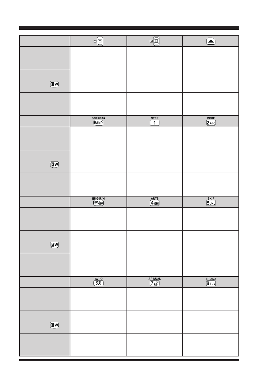
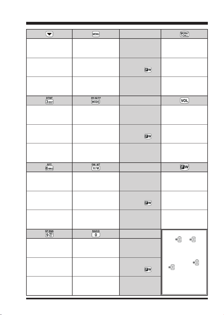
KEYPAD FUNCTIONS
ÚÚ
PRIMARY FUNCTION
(
PRESS KEY
)
SECONDARY FUNCTION
(
PRESS +
THIRD FUNCTION
(
PRESS AND HOLD KEY
PRIMARY FUNCTION
(
PRESS KEY
)
SECONDARY FUNCTION
(
PRESS +
THIRD FUNCTION
(
PRESS AND HOLD KEY
PRIMARY FUNCTION
(
PRESS KEY
)
Switches the “Upper”
frequency to be the
“Operating” (TX) Band.
)
)
)
)
No Action
Activates the
Dual Receive Feature.
(1) Moves operation to the
next-highest frequency band.
(2) Activates the Memory Bank
feature.
Moves operation to the
next-lowest frequency band
(1) Select the Bandwidth for
the VFO scanner.
(2) Select the Memory Scan
mode.
Reverses transmit and
receive frequencies while
working through a repeater.
Switches the “Lower”
frequency to be the
“Operating” (TX) Band.
No Action
Activates the
Dual Receive Feature.
Frequency entry digit “1”
Selects the synthesizer steps
to be used during VFO
operation.
No Action
Frequency entry digit “4”
Increases the VFO
frequency by one step or
moves the memory channel
to the next-highest channel.
Tunes the VFO frequency
upward in 1 MHz steps.
Activates the Scanner
Upward (toward a higher
frequency or a higher
channel number).
Frequency entry digit “2”
Selects the CTCSS Tone,
DCS code, EPCS code, or
Message.
No Action
Frequency entry digit “5”
SECONDARY FUNCTION
(
PRESS +
THIRD FUNCTION
(
PRESS AND HOLD KEY
PRIMARY FUNCTION
(
PRESS KEY
)
SECONDARY FUNCTION
(
PRESS +
THIRD FUNCTION
(
PRESS AND HOLD KEY
Switches operation to the
“Home” (favorite frequency)
)
Activates the EMERGENCY
)
Activates the Internet
Connection feature.
Selects the desired transmit
)
power output level.
)
No Action.
channel.
function.
Activates the ARTS feature.
No Action
Frequency entry digit “7”
Activates the AF Dual
function while receiving the
Broadcast Stations.
No Action
VX-8R OPERATING MANUAL4
Activates the Memory Scan
“Skip” channel selection
mode.
No Action
Frequency entry digit “8”
Activates the Spectrum
Analyzer (Spectra-Scope
feature.
No Action
TM
)
KEYPAD FUNCTIONS
Decreases the VFO
frequency by one step or
moves the memory channel
to the next-lowest channel.
Tunes the VFO frequency
downward in 1 MHz steps.
Activates the Scanner
Downward (toward a lower
frequency or a lower channel
number).
Frequency entry digit “3”
Selects the DTMF mode.
No Action
Frequency entry digit “6”
Selects the direction of the
uplink frequency shift (either
“–”, “+”, or “simplex”) during
repeater operation.
No Action
Activate the APRS (Automatic
Position Reporting System)
function.
No Action
Enter the Set Mode.
Selects the receive mode
among AM, FM,
and Wide FM.
Activates the CTCSS
or DCS operation.
Engage the Special
Search mode.
Switches frequency control
between the VFO and
Memory System.
Activates the “Memory Tune”
mode while in the Memory
Recall mode.
Activates the Priority (Dual
Watch) function.
PRIMARY FUNCTION
(
PRESS KEY
)
SECONDARY FUNCTION
(
PRESS +
)
THIRD FUNCTION
(
PRESS AND HOLD KEY
PRIMARY FUNCTION
(
PRESS KEY
)
SECONDARY FUNCTION
(
PRESS +
)
THIRD FUNCTION
(
PRESS AND HOLD KEY
PRIMARY FUNCTION
(
PRESS KEY
)
SECONDARY FUNCTION
(
PRESS +
)
THIRD FUNCTION
(
PRESS AND HOLD KEY
USA Version: Disables the Noise
and Tone Squelch System.
EXP Version: Activates the T.CALL
(1750 Hz) for repeater access.
Adjusts the Squelch
threshold level.
USA Version: Disables the Noise
and Tone Squelch System.
EXP Version: Activates the T.CALL
)
(1750 Hz) for repeater access.
No Action
Toggle the DIAL knob
function between the
“Frequency Control” and
“Receiver Audio Control”.
Rotate the DIAL knob while
holding this key to adjust the
)
audio volume level.
Activates the “Secondary”
key function.
Disables the “Secondary”
key function.
Activates the “Memory Write”
mode (for memory channel
)
storage).
NOTE
1: The and keys
Frequency entry digit “9”
Enters the “Special Memory”
mode.
No Action No Action
Frequency entry digit “0”
Enters the Broadcast
Reception mode.
PRIMARY FUNCTION
(
PRESS KEY
)
SECONDARY FUNCTION
(
PRESS +
)
THIRD FUNCTION
(
PRESS AND HOLD KEY
glows green when the
squelch opens, and
turns red during transmission.
2: Press the or
key to switch the
frequency display between the “Double-size
Character” and “Small
Character” mode while
)
Mono band operation.
VX-8R OPERATING MANUAL 5

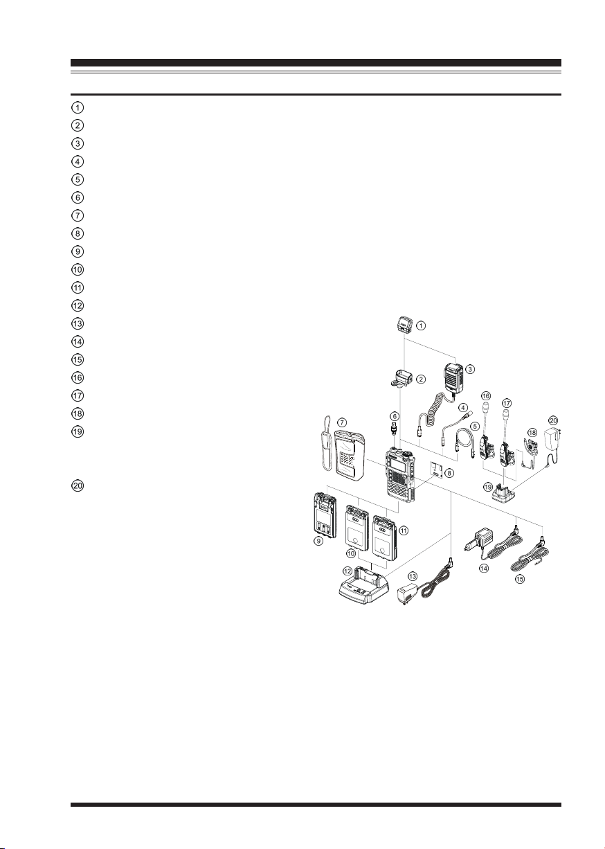
ACCESSORIES & OPTIONS
ACCESSORIES SUPPLIED WITH THE VX-8R
Antenna 1 pc YHA-65 (for USA version: Q3000185) or
YHA-64 (for EXP version: Q3000183)
Li-ion Battery Pack 1 pc FNB-101LI (7.4V/1,100mAh: AAG10X001)
Battery Charger 1 pc NC-86B (for USA version: Q9500149) or
NC-86C (for EXP version: Q9500150)
Connector Unit 1 pc (CB4392001)
Belt Clip 1 pc (RA1053600)
Screws 2 pcs (M3x10SUS: U24310020)
Plastic Cap 1 pc (RA1054200)
Sheet 2 pcs (RA1066900)
Operating Manual 1 pc
Warranty Card 1 pc
VX-8R OPERATING MANUAL6
ACCESSORIES & OPTIONS
AVAILABLE OPTIONS FOR YOUR VX-8R
FGPS-2 GPS Antenna Unit
CT-136 GPS Antenna Adapter
MH-74A7A Waterproof Speaker/Microphone
CT-131 Microphone Adapter
CT-134 Clone Cable
CN-3 BNC-to-SMA Adapter
CSC-93 Soft Case
BU-1 Bluetooth® Unit
FBA-39 3 x “AA” Cell Battery Case (batteries not supplied)
FNB-101LI Li-ion Battery Pack (7.4V/1,100 mAh)
FNB-102LI Li-ion Battery Pack (7.4V/1,800 mAh)
CD-41 Rapid Charger (requires NC-86B/C/U)
NC-86B/C/UÚBattery Charger for the CD-41
E-DC-5B DC Cable w/Noise Filter
E-DC-6 DC Cable; plug and wire only
BH-2 Bluetooth® Headset (Monaural)
BH-1 Bluetooth® Headset (Stereo)
FEP-4 Earphone for BH-1
CD-40 Charger Cradle for
the BH-1/BH-2 (requires NC-85B/C/U)
NC-85B/C/UÚBattery Charger for
the CD-40
Ú: “B” suffix is for use with 120 VAC
(Type-A plug), “C” suffix is for use with
230 VAC (Type-C plug), and “U” suffix is for use with 230 VAC (Type-BF
plug).
Availability of accessories may vary. Some accessories are supplied as standard per local
requirements, while others may be unavailable in some regions. Consult your Yaesu Dealer
for details regarding these and any newly-available options. Connection of any non-Yaesu
approved accessory, should it cause damage, may void the Limited Warranty on this apparatus.
VX-8R OPERATING MANUAL 7
INSTALLATION OF ACCESSORIES
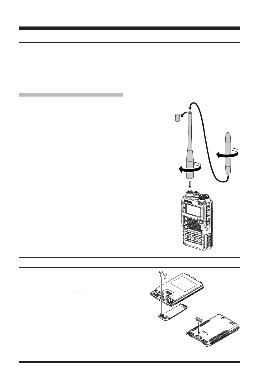
ANTENNA INSTALLATION
The supplied antenna provides good results over the entire frequency range of the transceiver. However, for enhanced base station medium-wave and shortwave reception, you
may wish to connect an external (outside) antenna. The supplied antenna consists of two
sections: the “Base Antenna” (used for operation above 50 MHz), and the “Extender Element” (used for monitoring of frequencies below 50 MHz).
TO INSTALL THE SUPPLIED ANTENNA
Hold the bottom end of the antenna, then screw it onto the
mating connector on the transceiver until it is snug. Do not
over-tighten by use of extreme force.
When operating the VX-8R on the 50 MHz band and lower
frequencies, disconnect the antenna cap from the base antenna,
then screw the Extender Element onto the Antenna Base. Of
course, the VX-8R may be operated on frequencies higher
than the 50 MHz band while the Extender Element is still attached to the Antenna Base.
Notes:
Never transmit without having an antenna connected.
Carefully turn the supplied antenna onto the SMA jack.
Never twist the upper part of the antenna while screwing
it onto the mating connector of the transceiver.
If using an external antenna for transmission, ensure that
the SWR presented to the transceiver is 1.5:1 or lower.
Take care, do not lose the antenna cap when removing it
from the Base Antenna.
BELT CLIP INSTALLATION
Install the supplied Belt Clip to the FNB-101LI
Battery Pack using the supplied two screws
(Figure 1). Use only the screws included with
the Belt Clip to mount the Belt Clip to the back
of the Battery Pack!
If you do not need the Belt Clip, install the sup-
plied Plastic Cap to the Battery Pack (Figure
2). If you install the belt clip later, push the Plastic Cap out with a small tool or screwdriver.
Figure 1
Figure 2
VX-8R OPERATING MANUAL8
INSTALLATION OF ACCESSORIES
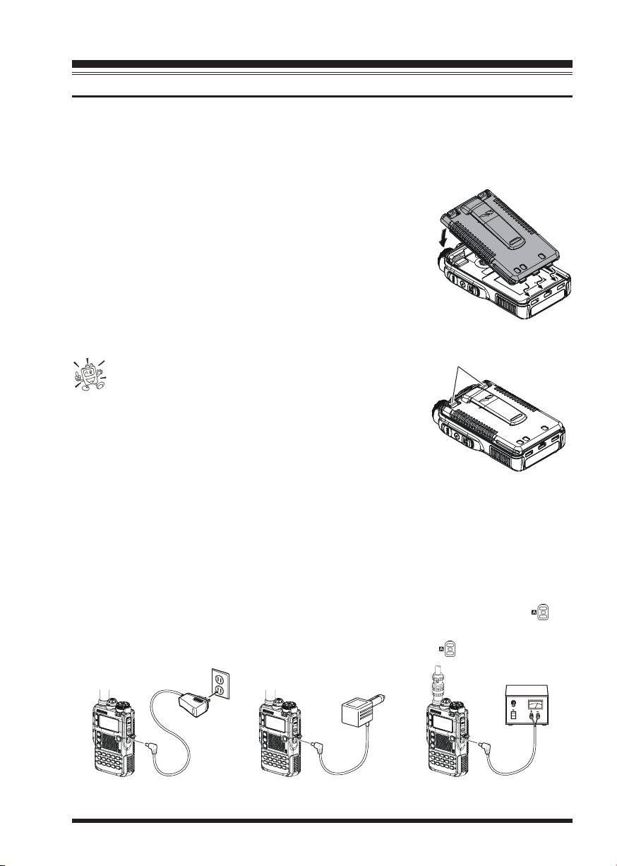
INSTALLATION OF FNB-101LI BATTERY PACK
The FNB-101LI is a high-performance Lithium-Ion battery providing high capacity in a
very compact package. Under normal use, the FNB-101LI may be used for approximately 300 charge cycles, after which operating time may be expected to decrease. An old
battery pack, which is displaying diminished capacity should be replaced with a new one.
To install the FNB-101LI Battery Pack, carefully mate the
battery’s three alignment tabs with their corresponding alignment slots on the transceiver bottom case, then gently press
the top side of the Battery Pack until it locks in place with a
“click”.
To remove the Battery Pack, turn the transceiver off and
remove any protective cases. Press the Battery Pack Release
Knobs downward to unlock the latch, then remove the Battery Pack from the transceiver.
The VX-8R battery must be correctly installed, to
maintain the waterproof integrity.
BATTERY PACK RELEASE KNOB
INSTALL
REMOVE
If the battery has never been used, or its charge is depleted, it may be charged by connecting the NC-86B/C Battery Charger, as shown in the illustration, to the EXT DC jack. If
only 12 ~ 16 Volt DC power is available, the optional E-DC-5B DC Adapter (with its
cigarette lighter plug) or E-DC-6 DC Cable may also be used for charging the battery, as
shown in the illustration.
While the battery is being charged, the display will indicate “
will glow red. The S-meter will deflect according to the charging status. When charging is
finished, the display will change to indicate “
COMPLETECOMPLETE
COMPLETE” and the key will glow green.
COMPLETECOMPLETE
CHARGINGCHARGING
CHARGING” and the key
CHARGINGCHARGING
E-DC-6E-DC-5BNC-86
VX-8R OPERATING MANUAL 9
INSTALLATION OF ACCESSORIES
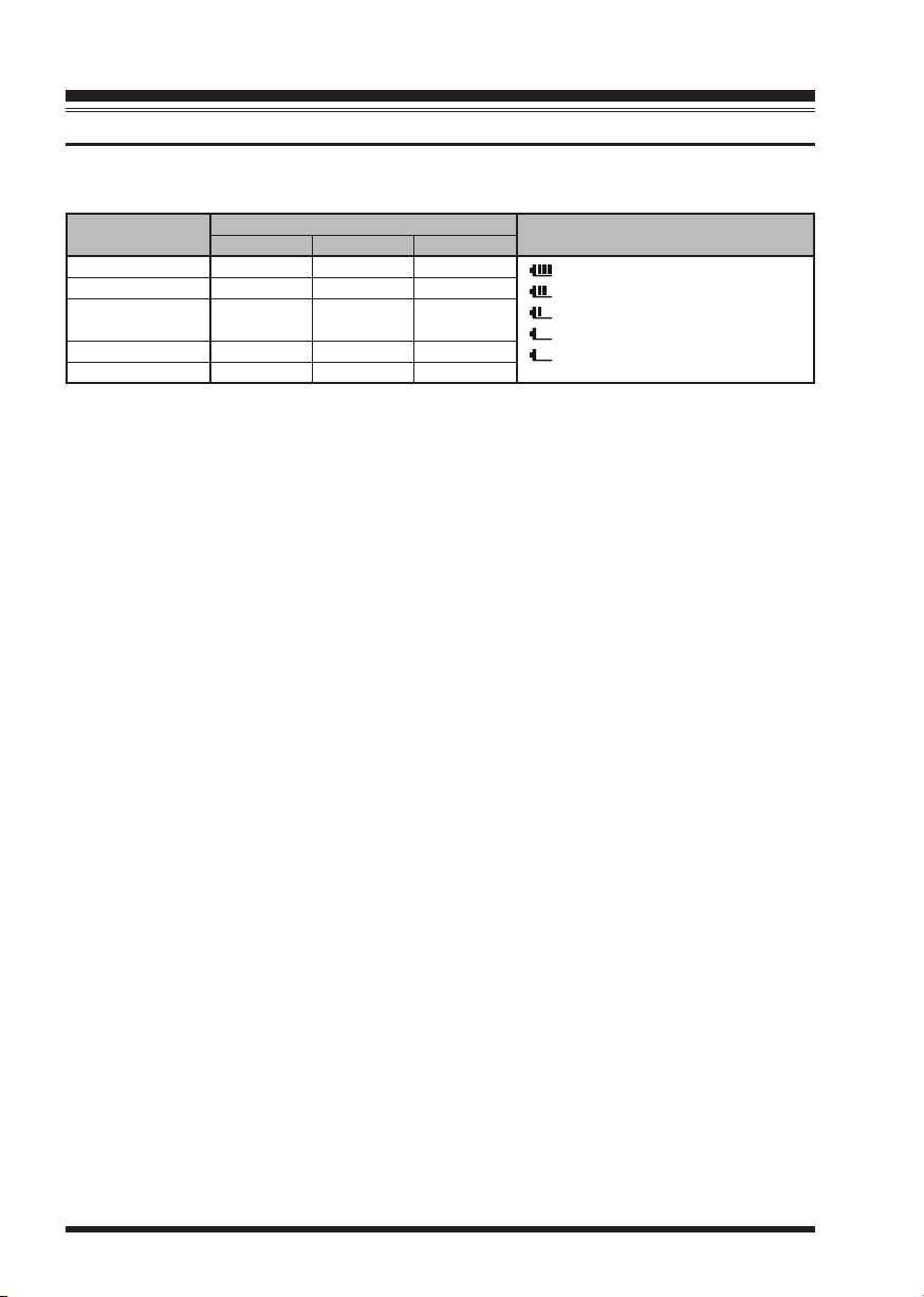
BATTERY LIFE INFORMATION
When the battery charge is almost depleted, a “Low Voltage” indicator will appear on the
display. When this icon appears, it is recommended that you charge the battery soon.
OPERATING BAND
(1)
50 MHz
144 MHz
222 MHz
(
USA version
430 MHz
Broadcast Band
(1) TX 6 sec., RX 6 sec. and Squelched 48 sec (continuous operating cycle).
(2) Continuous signal reception.
(1)
(1)
)
(1)
(2)
BATTERY LIFE (APPROX.
FNB-101LI
5.5 hours
5.0 hours
6.0 hours
5.0 hours
13 hours
FNB-102LI
9.0 hours
8.5 hours
11 hours
8.0 hours
20 hours
The present battery voltage can be displayed manually on the LCD, by following the
instructions on page 119.
Battery capacity may be reduced during extremely cold weather. Keeping the radio inside
your parka may help preserve the full charge capacity.
)
FBA-39
20 hours
17 hours
20 hours
16 hours
20 hours
BATTERY INDICATOR
: Full battery power
: Enough battery power
: Low battery power
: Poor battery power
(
w/Blink): charge
(or replace) the battery
VX-8R OPERATING MANUAL10
INSTALLATION OF ACCESSORIES
INSTALLATION OF FBA-39 ALKALINE BATTERY CASE (OPTION
The optional FBA-39 Battery Case allows receive monitoring using three “AA” size Alkaline batteries. Alkaline batteries can also be used for low power transmission in an
emergency. The power output will only be selectable 1 W/50 mW (for 50/144/430 MHz
FM) or 500 mW/50 mW (for 222 MHz FM), or 1 W fixed (for 50 MHz AM).
)
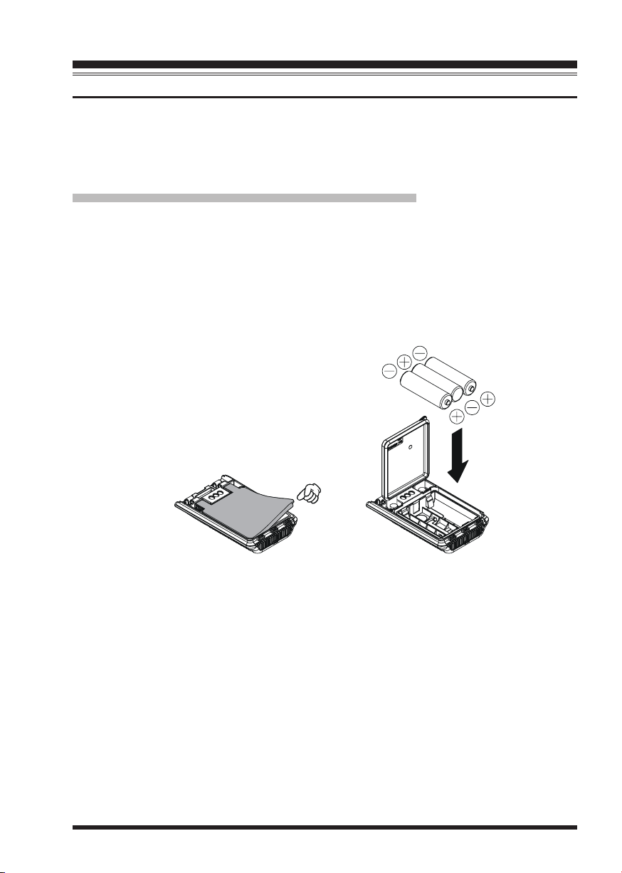
TO INSTALL ALKALINE BATTERIES INTO THE FBA-39
1. Lift up the lower right corner of the rubber cover, and then open the cover (Figure 1).
2. Referring to Figure 2, slide the batteries into the FBA-39 as shown in the illustration,
with the Negative
FBA-39.
3. Close the rubber cover.
4. Install the FBA-39 in the transceiver in the same manner as the FNB-101LI.
[–]
side of the batteries touching the spring connections inside the
Figure 1 Figure 2
The FBA-39 does not provide connections for charging, since Alkaline cells cannot be
re-charged. Therefore, the NC-86B/C, E-DC-5B, or E-DC-6 may safely be connected to
the EXT DC jack when the FBA-39 is installed.
Notes:
The FBA-39 is designed for use only with AA-type Alkaline cells.
If you do not use the VX-8R for a long time, remove the Alkaline batteries from the
FBA-39, as battery leakage could cause damage to the FBA-39 and/or the transceiver.
VX-8R OPERATING MANUAL 11
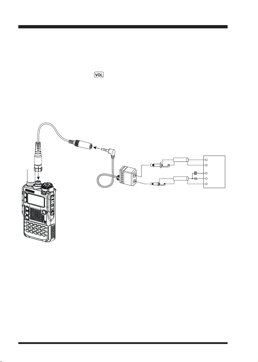
INTERFACE OF PACKET TNCS
The VX-8R may be used for Packet operation, using the optional CT-44 and CT-131
microphone adapter (available from your Yaesu dealer) for easy interconnection to commonly-available connectors wired to your TNC. You may also build your own cable using
a four-conductor miniature phone plug.
The audio level from the receiver to the TNC may be adjusted by rotating the DIAL knob
while pressing and holding the key, as with voice operation. The input level to the
VX-8R from the TNC should be adjusted at the TNC side; the optimum input voltage is
approximately 5 mV at 2000 Ohms.
Be sure to turn the transceiver and TNC off before connecting the cables, to prevent voltage spikes from damaging your transceiver.
CT-131 Microphone Adapter
CT-44 Microphone Adapter
TNC
2 k
SP
GND
MIC
PTT
Ω
GND
EAR
3.5
MIC
2.5
φφ
φ
φφ
Plug
φφ
φ
φφ
Plug
10 Fµ
VX-8R OPERATING MANUAL12
OPERATION
Hi! I’m R. F. Radio, and I’ll be helping you along as you learn the many
features of the VX-8R. I know you’re anxious to get on the air, but I encour-
age you to read the “Operation” section of this manual as thoroughly as
possible, so you’ll get the most out of this fantastic new transceiver. Now. . .let’s get
operating!
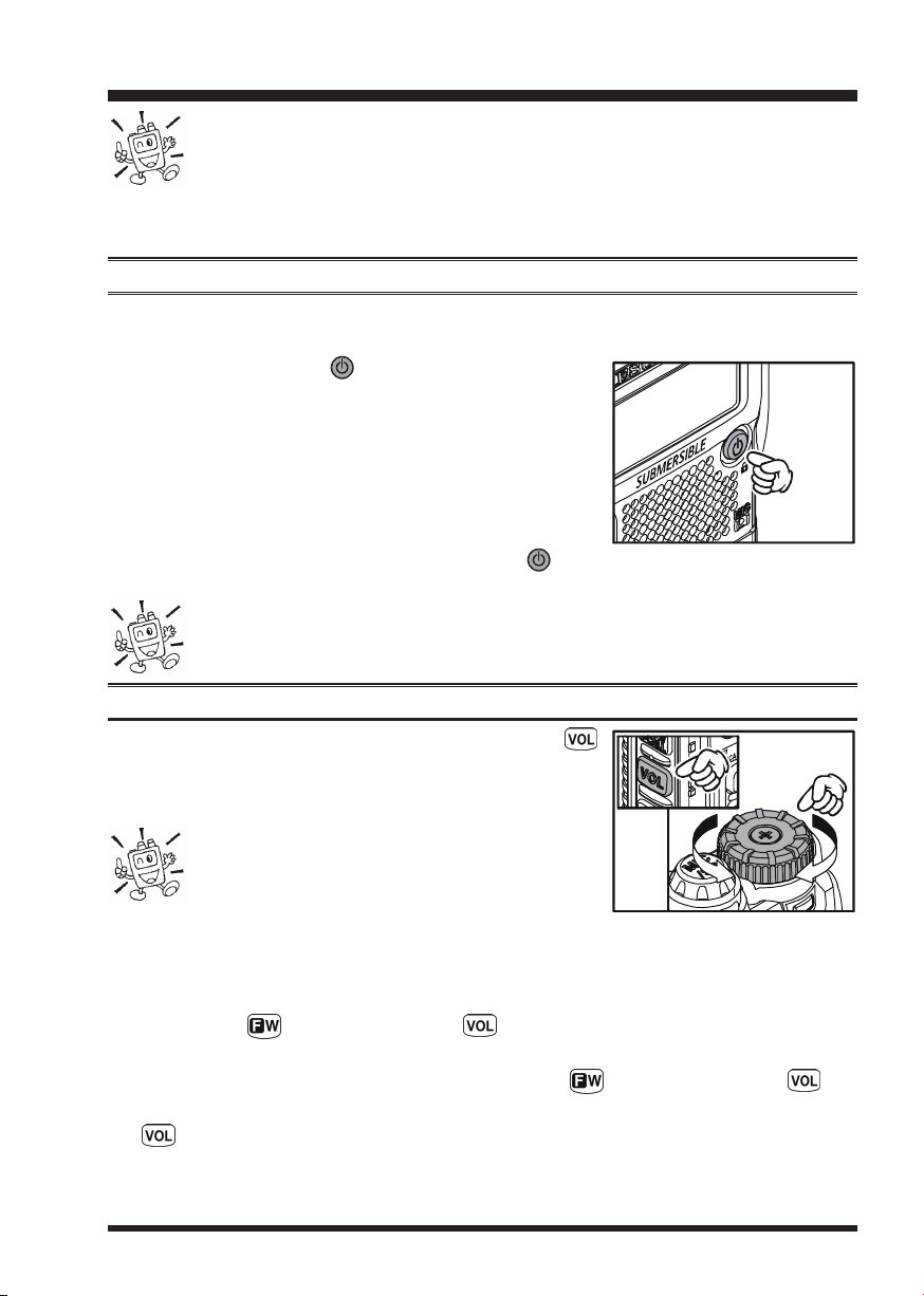
SWITCHING POWER ON AND OFF
1. Be sure the battery pack is installed, and that it is fully charged. Connect the antenna
to the top panel ANTENNA jack.
2. Press and hold in the (PWR) switch (on the right
side of the front panel) for 2 seconds. Two beeps will be
heard when the switch has been held long enough. The
opening message will appear briefly on the display, then
the frequency display will appear. After another two seconds, the receive-mode Battery Saver function will become active, unless you have disabled it (see page 125).
3. To turn the VX-8R off, press and hold in the (PWR) switch again for 2 seconds.
If you don’t hear the two “Beep” tones when the radio comes on, the Beeper
may have been disabled via the Menu system. See page 27, which tells you
how to reactivate the Beeper.
ADJUSTING THE VOLUME LEVEL
Rotate the DIAL knob while pressing and holding the
key to set the desired audio level. Clockwise rotation increases the volume level.
1) The Volume level may be set on the
“A-Band” and “B-Band” separately.
2) You may set the Audio Output Level to the
Speaker, and the Earphone Output Level individually. The
“SP VOLUME” notation appears in the S- & PO meter area while adjusting the Speaker
Output Level. The “HP VOLUME” notation appears in the S- & PO meter area while
adjusting the Earphone Output Level.
3) Pressing the key followed by the key, the DIAL knob function changes to
the Volume Level adjustment instead of the frequency control. In this case, the “Volume
Level Indicator” on the display blinks. Pressing the key followed by the key
again, returns the DIAL knob function to the frequency control. You may also change
the key function via Set Mode Item 107: VOLUME MODE. See page 133 for details.
VX-8R OPERATING MANUAL 13
OPERATION
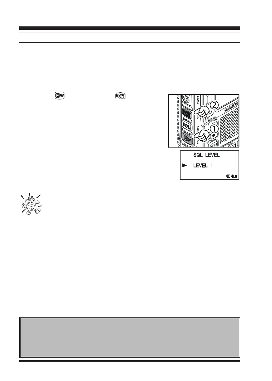
SQUELCH ADJUSTMENT
The VX-8R’s Squelch system allows you to mute the background noise when no signal is
being received. Not only does the Squelch system make “standby” operation more pleasant, it also significantly reduces battery current consumption.
The Squelch system may be adjusted independently for the FM and Wide-FM (FM Broadcast) modes.
1. Press the key, then press the key on the left
side of the radio. This provides a “Short-cut” to Set
Mode Item
2. Now, rotate the DIAL knob to the point where the background noise is just silenced (typically at a setting of
about “3” or “4” on the scale); this is the point of maximum sensitivity to weak signals.
3. When you are satisfied with the Squelch threshold setting,
press the PTT key briefly to save the new setting and exit to
normal operation.
4. You may also adjust the Squelch setting by using the “Set”
(Menu) mode. See page 157 for details.
feature will keep your radio quiet until a call is received from a station sending a carrier
which contains a matching (sub audible) CTCSS tone. Or if your friends have radios
equipped with DCS (Digital Coded Squelch) like your VX-8R, try using that mode for
silent monitoring of busy channels.
92: SQL LEVEL92: SQL LEVEL
92: SQL LEVEL.
92: SQL LEVEL92: SQL LEVEL
1) The Squelch level may be set on the “Main” and “Sub” bands separately.
2) If you’re operating in an area of high RF pollution, you may need to
consider “Tone Squelch” operation using the built-in CTCSS Decoder. This
24-HOUR CLOCK
The VX-8R has a 24-hour clock with a calendar which covers all dates from January 1, 2000 through December 31, 2099. Set the clock according to the “Clock Set”
column on page 120.
VX-8R OPERATING MANUAL14
OPERATION
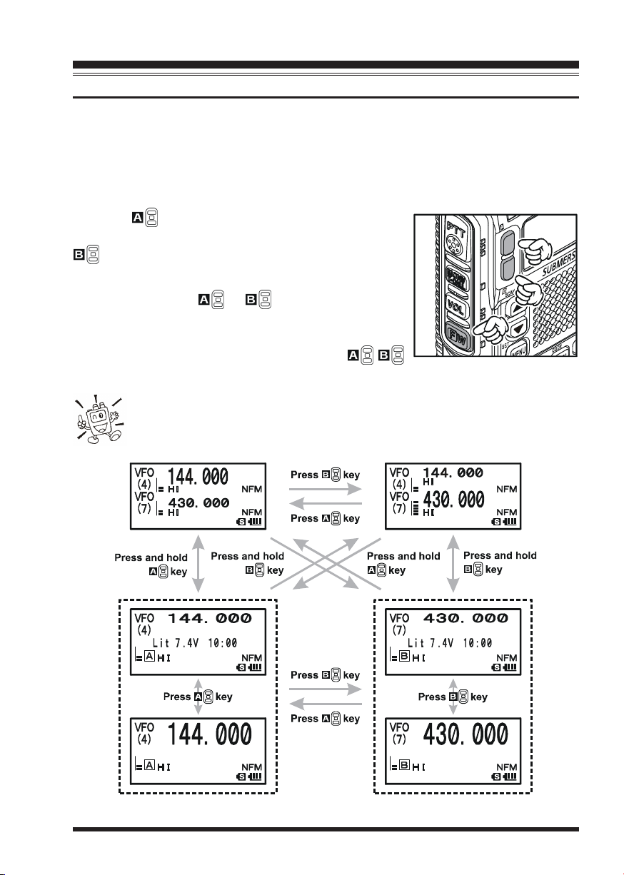
SELECTING THE OPERATING BAND
In the factory default configuration, the VX-8R operates in the “Dual Receive” mode.
During Dual Receive operation, the “A-Band” frequency will be displayed on the upper
part of the LCD, and the “B-Band” frequency will be displayed on the lower part. The
“Operating” band (the band on which transmission and band/frequency changes are possible) is shown in large characters, and “Receive only” band is shown in small characters.
Press the key briefly to engage the “A-Band” frequency as the “Operating” band. Alternatively, press the
key briefly to engage the “B-Band” frequency, as de-
scribed previously.
Press and hold in the or key for 1/2 seconds to
switch to Mono Band Operation. During Mono band operation, you may change the display between “double-size
character” and “large character” by pressing the /
key.
When monitoring the receive audio with stereo earphones, the audio from
the “A-Band” is only heard in the left ear, and the audio from the “B-Band”
is only heard in the right ear.
VX-8R OPERATING MANUAL 15
OPERATION
SELECTING THE FREQUENCY BAND
The VX-8R covers an incredibly
wide frequency range, over
which a number of different operating modes are used. Therefore, the VX-8R’s frequency
coverage has been divided into
different operating bands. Each
band has its own preset channel
steps and operating modes. You
can change the channel steps and
operating modes later, if you like (see page 29).
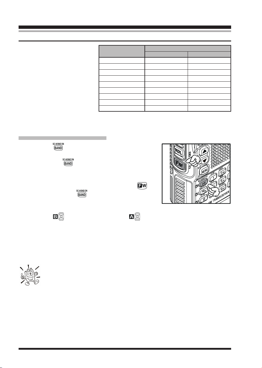
TO CHANGE OPERATING BANDS
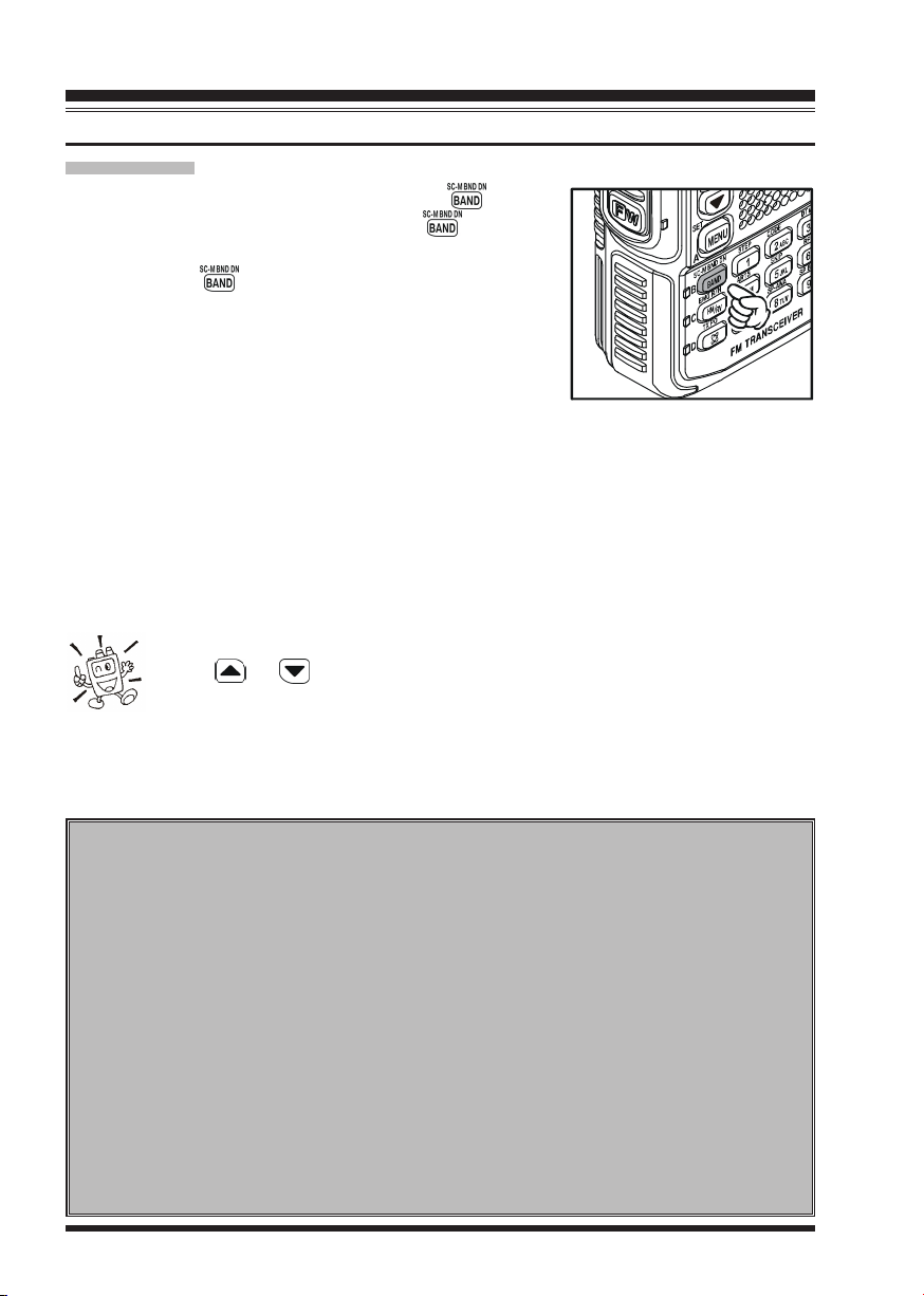
1. Press the key repeatedly. You will see the LCD
indication change to a higher frequency band each time
you press the key. A Band Number according to
the receiving frequency is also displayed.
2. If you wish to move the operating band selection downward (toward lower frequencies), press the key
first, then press the key.
3. The VX-8R uses a dual VFO system (described previously). To switch TX/RX operation from the “VFO-A” to the “VFO-B” instantly,
press the key briefly. Pressing the key will return TX/RX operation to
“VFO-A”. The frequency band shown in “Large” characters is the band on which
transmission is possible; the band shown in “Small” characters may only be used for
reception.
4. Once you have selected the desired band, you may initiate manual tuning (or scanning). See the discussions on the next page.
OPERATING BAND
[
BAND NUMBER
SW Band
50 MHz Band
AIR Band
VHF HAM Band
VHF TV Band
INFO 1 Band
UHF HAM Band
UHF TV Band
INFO 2 Band
]
[1]
[2]
[3]
[4]
[5]
[6]
[7]
[8]
[9]
774-999.99 MHz
FREQUENCY RANGE
“VFO-A”
1.8-30 MHz
30-76 MHz
108-137 MHz
137-174 MHz
174-222 MHz
222-420 MHz
420-470 MHz
470-774 MHz
USA Version: Cellular Blocked
Ú
“VFO-B”
108-137 MHz
137-174 MHz
174-222 MHz
222-420 MHz
420-470 MHz
470-580 MHz
Ú
–
30-76 MHz
–
1) SW Band and Information Band reception is only possible on the “VFO-A”.
2) The VX-8R has an AM/FM Broadcast band radio. You can receive these
bands independently. See page 22 for details.
3) If desired, you may omit (skip) one or more bands from the band selection loop for
faster recall of your favorite operating bands. See page 132 for details.
VX-8R OPERATING MANUAL16
OPERATION
FREQUENCY NAVIGATION
The VX-8R will initially be operating in the “VFO” mode, as just described. This is a frequency
step system which allows free tuning throughout the currently-selected operating band.
Three basic frequency navigation methods are available on the VX-8R:
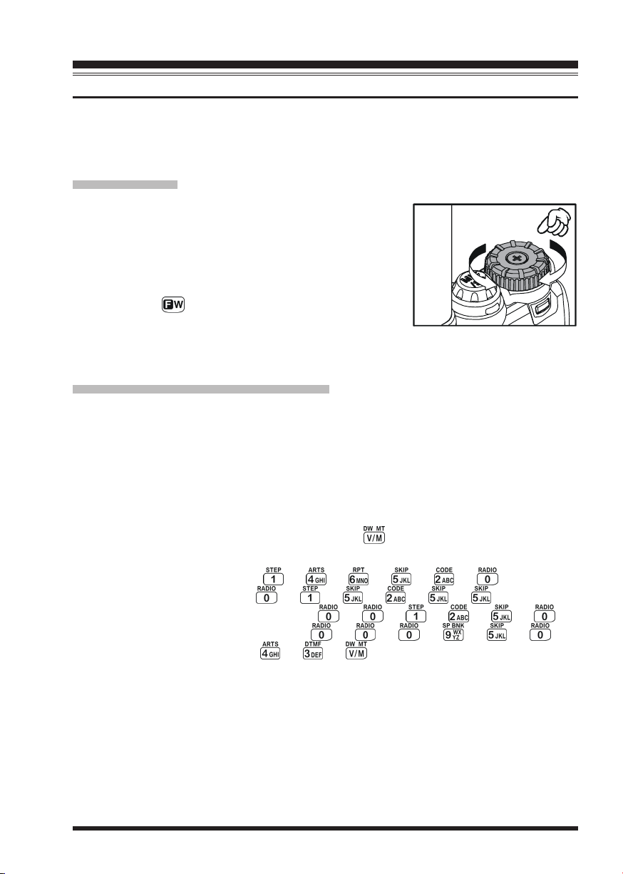
1) TUNING DIAL
Rotation of the DIAL knob allows tuning in the pre-programmed steps established for the current operating band.
Clockwise rotation of the DIAL knob causes the VX-8R to
be tuned toward a higher frequency, while counter-clockwise rotation will lower the operating frequency.
If you press the key briefly, then rotate the DIAL knob,
frequency steps of 1 MHz will be selected. This feature is
extremely useful for making rapid frequency excursions over the wide tuning range of the
VX-8R.
2) DIRECT KEYPAD FREQUENCY ENTRY
The desired operating frequency may be entered directly from the keypad.
The operating mode will automatically be set once the new frequency is entered via the
keypad.
To enter a frequency from the keypad, just press the numbered digits on the keypad in the
proper sequence. There is no “Decimal point” key on the VX-8R, so if the frequency is below
100 MHz (e.g. 15.150 MHz), any required leading zeroes must be entered. However, there is
a short-cut for frequencies ending in zero - press the key after the last non-zero digit.
Examples:
To enter 146.520 MHz, press Æ Æ Æ Æ Æ
To enter 15.255 MHz, press Æ Æ Æ Æ Æ
To enter 1.250 MHz (1250 kHz), press Æ Æ Æ Æ Æ
To enter 0.950 MHz (950 kHz), press Æ Æ Æ Æ Æ
To enter 430.000MHz, press Æ Æ
VX-8R OPERATING MANUAL 17
OPERATION
FREQUENCY NAVIGATION
3) SCANNING
From the VFO mode, press and hold in the key for
one second, and while still holding in the key, rotate
the DIAL knob to select the bandwidth for the VFO scanner. Release the key to begin scanning toward a higher
frequency. The scanner will stop when it receives a signal
strong enough to break through the Squelch threshold. The
VX-8R will then hold on that frequency according to the
setting of the “
SUMESUME
SUME).
SUMESUME
If you wish to reverse the direction of the scan (i.e. toward a lower frequency, instead of a
higher frequency), just rotate the DIAL knob one click in the counter-clockwise direction
while the VX-8R is scanning. The scanning direction will be reversed. To revert to scanning toward a higher frequency once more, rotate the DIAL knob one click clockwise.
Press the PTT switch briefly to cancel the scanning. See page 60 for more details regarding Scan Operation.
RESUMERESUME
RESUME” mode (Menu Item
RESUMERESUME
You may initiate upward or downward scanning by pressing and holding
either or key for one second, respectively. In this case, the scanner
scans the bandwidth that was previously selected.
83: SCAN RE-83: SCAN RE-
83: SCAN RE-
83: SCAN RE-83: SCAN RE-
Dual Receive Notice
The VX-8R may receive very strong signals on the Image frequency, and/or the
receiver sensitivity may be somewhat reduced by the combination of the “A-Band”
and “B-Band” frequencies while Dual Receive operation is engaged.
If you experience interference that you suspect may be coming in via an “Image”
path, you may calculate the possible frequencies using the formulas below. This
information may be used in the design of effective countermeasures such as traps,
etc.
9.8304 MHz x n 11.7 MHz x n (n is an integer: 1, 2, 3, …)
4.9152 MHz x
“A-Band” Freq. = (“B-Band” Freq. ± 46.35 MHz) x n
“B-Band” Freq. = (“A-Band” Freq. ± 47.25 MHz) x n (@ “A-Band” = NFM)
“B-Band” Freq. = (“A-Band” Freq. ± 45.8 MHz) x
n 6.1440 MHz x n
n (@ “A-Band” = WFM)
VX-8R OPERATING MANUAL18
OPERATION
TRANSMISSION
Once you have set up an appropriate frequency inside one of the three (or four) Amateur
bands on which the VX-8R can transmit (50 MHz, 144 MHz, or 430 MHz, plus 222 MHz
on the USA version), you’re ready to transmit. These are the most basic steps; more advanced aspects of transmitter operation will be discussed later.
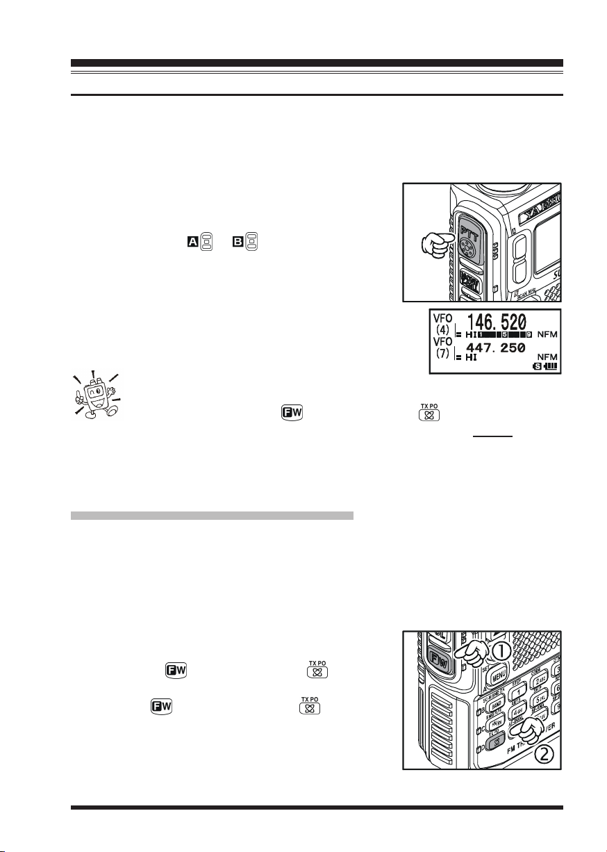
1. To transmit, press the PTT switch, and speak into the
front panel microphone (located in the lower right-hand
corner of the speaker grille) in a normal voice level.
The LED of the or which is designated the
“Main” band will glow red during transmission.
2. To return to the receive mode, release the PTT switch.
3. During transmission, the relative power level will be
indicated on the LCD. Additionally, the “L1”, “L2”, “L3”,
or “HI” icon will appear at the left side of the PO meter,
corresponding with the “Power” Level setting.
1) If you’re just talking to friends in the immediate
area, you’ll get much longer battery life by switching to Low Power opera-
tion. To do this, press the key, then press the key so that the “Low
Power” icon appears at the bottom of the display. And don’t forget: always have an
antenna connected when you transmit.
2) Transmission is not possible on “Sub” band and any operating bands other than the
50 MHz, 144 MHz, 222 MHz (USA version), and 430 MHz bands on the “Main” band.
CHANGING THE TRANSMITTER POWER LEVEL
You can select between a total of four transmitter power levels on your VX-8R. The exact
power output will vary somewhat, depending on the voltage supplied to the transceiver.
With the standard FNB-101LI Battery Pack and external DC source, the power output
levels available are: “L1”, “L2”, “L3”, or “HI”
To change the power level:
1. The default setting for the power output is “High;” in
this configuration, the display shows the “HI” icon.
Pressing the key, followed by the key, causes
the power level “L1”, “L2”, or “L3” to appear.
2. Press the key, followed by the key (repeat-
edly, if necessary) to make the “HI” icon appear and
restore “High Power” operation.
VX-8R OPERATING MANUAL 19
OPERATION
TRANSMISSION
1) The VX-8R is smart! You can set up Low power on one band (like UHF),
while leaving VHF on High power, and the radio will remember the different
settings on each band. And when you store memories, you can store High
and Low power settings separately in each memory, so you don’t waste battery power
when using very close-in repeaters!
2) When you are operating on one of the Low power settings, you can press the key,
then press the PTT switch,
to cause the VX-8R to transmit (temporarily) on High
power. After one transmission, the power level will revert to the previously-selected Low power setting.
OPERATING BAND
50/144/430 MHz
222 MHz FM
50 MHz AM
FNB-101LI/-102LI or
EXT DC (7.4 V
HI: 5.0 W, L3: 2.5 W,
FM
L2: 1.0 W, L1: 0.05 W
HI: 1.5 W, L3: 1.0 W,
L2: 0.5 W, L1: 0.05 W
1.0 W (Fixed
VOX OPERATION
The VOX system provides automatic transmit/receive switching based on voice input to the
microphone. With the VOX system enabled, you do not need to press the PTT switch in order
to transmit, and it is not necessary to use a VOX headset in order to utilize VOX operation.
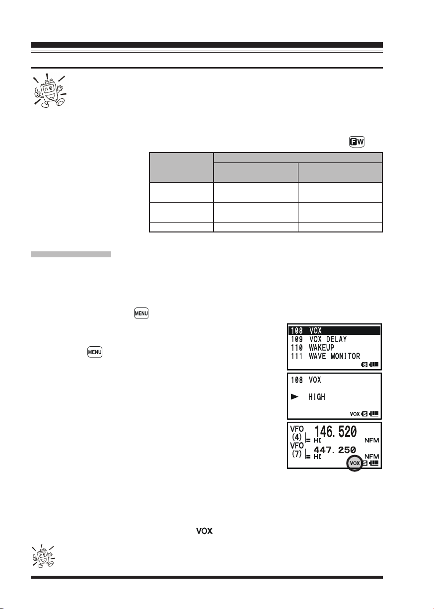
1. Press and hold in the key for one second to enter the Set mode.
2. Rotate the DIAL knob to select the Set Mode Item
VOXVOX
VOX.
VOXVOX
3. Press the key briefly to enable adjustment of this Set
Mode Item.
4. Rotate the DIAL knob to select the desired VOX Gain level
HIGHHIGH
(“
HIGH” or “
HIGHHIGH
5. When you have made your choice, press the PTT switch to
save the new setting and return to normal operation.
6. Without pressing the PTT switch, speak into the VX-8R
microphone in a normal voice level. When you start speaking, the transmitter should be activated automatically. When
you finish speaking, the transceiver should return to the receive mode (after a short delay).
LOWLOW
LOW”).
LOWLOW
TRANSMIT POWER
)
)
108:108:
108:
108:108:
FBA-39
(
w/Fresh Batteries
L2: 1.0 W,
L1: 0.05 W
L2: 0.5 W,
L1: 0.05 W
1.0 W (Fixed
)
)
To cancel VOX and return to PTT operation, just repeat the above procedures, selecting
OFFOFF
“
OFF” in step 4 above.
OFFOFF
When the VOX system is activated, the “ ” icon will appear on the display.
The VOX is activated by the VX-8R. The optional MH-74A7A Speaker/Microphone is ignored.
VX-8R OPERATING MANUAL20
OPERATION
TRANSMISSION
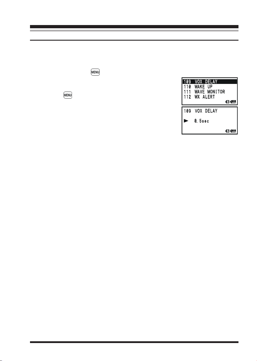
Adjust the VOX “Hang-Time” (the transmit-receive delay after the cessation of speech)
from the Set Mode Item
different delay time:
1. Press and hold in the key for one second to enter the Set mode.
2. Rotate the DIAL knob to select the Set Mode Item
VOX DELAYVOX DELAY
VOX DELAY.
VOX DELAYVOX DELAY
3. Press the key briefly to enable adjustment of this Set
Mode Item.
4. Rotate the DIAL knob to select the desired delay time
0.5sec0.5sec
(“
0.5sec”, “
0.5sec0.5sec
3.0sec3.0sec
“
3.0sec”).
3.0sec3.0sec
5. When you have made your choice, press the PTT switch to
save the new setting and return to normal operation.
1.0sec1.0sec
1.0sec”, “
1.0sec1.0sec
109: VOX DELAY109: VOX DELAY
109: VOX DELAY. The default delay is 0.5 second. To set a
109: VOX DELAY109: VOX DELAY
109:109:
109:
109:109:
1.5sec1.5sec
1.5sec”, “
1.5sec1.5sec
2.0sec2.0sec
2.0sec”, “
2.0sec2.0sec
2.5sec2.5sec
2.5sec”, or
2.5sec2.5sec
VX-8R OPERATING MANUAL 21
OPERATION
AM AND FM BROADCAST RECEPTION
The VX-8R includes provision for reception of AM and FM broadcasts. FM broadcast
reception, utilizes a wide-bandwidth filter and stereo decoder which provides excellent
fidelity.
The AM and FM Broadcast reception is only possible on “VFO-A”.
1. Press the key briefly to engage the “VFO-A” as the “Operating” band.
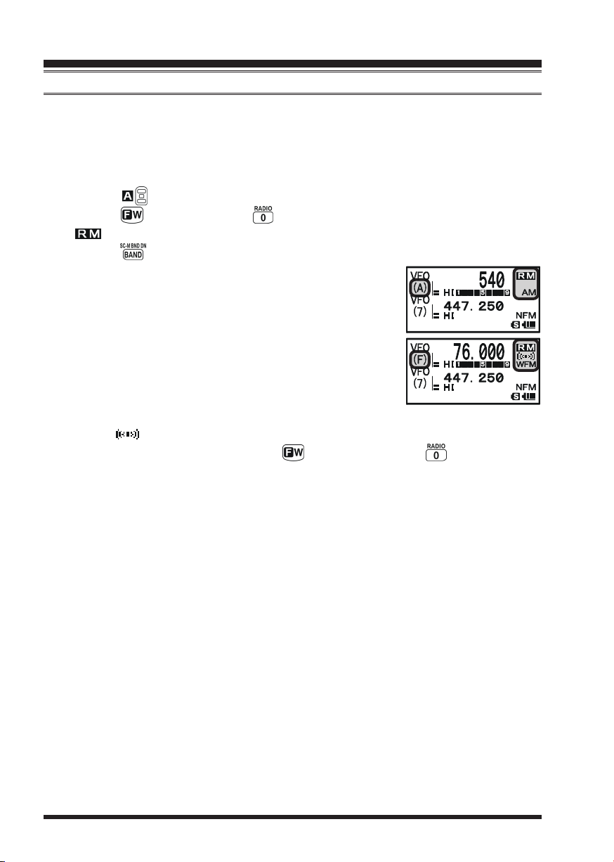
2. Press the key, then press the key to enter the Broadcast Reception mode. The
“ ” icon will appear on the display while in the Broadcast Reception mode.
3. Press the key to toggle the receiver between the “AM broadcast” and “FM broadcast” bands.
The AM broadcast coverage is 510 to 1790 kHz. The Band
Number changes to “
ing Mode icon changes to “AM”.
The FM broadcast coverage is 76.00 to 107.90 MHz and
utilizes Wide-FM mode. The Band Number changes to “
(which means FM) and an Operating Mode icon changes to
“WFM”.
4. Rotate the DIAL knob to select the desired station. When receiving an FM stereo
signal, “ ” icon will appear on the display.
5. To exit to normal operation, press the key followed by the key.
AA
A” (which means AM) and an Operat-
AA
FF
F”
FF
VX-8R OPERATING MANUAL22

OPERATION
AM AND FM BROADCAST RECEPTION
ANTENNA SELECTION
To select the antenna for the AM Broadcast Reception:
1. Press and hold the key for one second to enter the Set Mode.
2. Rotate the DIAL knob to select Set Mode Item
3. Press the key briefly to enable the antenna selection.
4. Rotate the DIAL knob to select the AM antenna to be used: “
(Uses the internal Bar Antenna) or “
Antenna and the Rubber Flex Antenna).
5. When you finish the selection, press the PTT switch to exit from the Menu
mode and return to the Broadcast Reception mode.
To select the antenna for the FM Broadcast Reception:
1. Press and hold the key for one second to enter the Set Mode.
2. Rotate the DIAL knob to select Set Mode Item
3. Press the key briefly to enable the antenna selection.
4. Rotate the DIAL knob to select the antenna to be used: “
(Uses the Rubber Flex Antenna) or “
tenna).
5. When you finish the selection, press the PTT switch to exit from the Menu
mode and return to the Broadcast Reception mode.
BAR & EXTBAR & EXT
BAR & EXT” (Uses both the internal Bar
BAR & EXTBAR & EXT
EAR PHONEEAR PHONE
EAR PHONE” (Uses the Earphone An-
EAR PHONEEAR PHONE
1: ANTENNA AM1: ANTENNA AM
1: ANTENNA AM.
1: ANTENNA AM1: ANTENNA AM
BAR ANTENNABAR ANTENNA
BAR ANTENNA”
BAR ANTENNABAR ANTENNA
2: ANTENNA FM2: ANTENNA FM
2: ANTENNA FM.
2: ANTENNA FM2: ANTENNA FM
EXT ANTENNAEXT ANTENNA
EXT ANTENNA”
EXT ANTENNAEXT ANTENNA
If you wish to output the audio of the FM Broadcast station to the VX-8R internal
speaker while using the earphone antenna, select Set Mode Item
OUTOUT
OUT to “
OUTOUT
SPEAKERSPEAKER
SPEAKER”.
SPEAKERSPEAKER
90: SPEAKER90: SPEAKER
90: SPEAKER
90: SPEAKER90: SPEAKER
VX-8R OPERATING MANUAL 23
OPERATION
AM AND FM BROADCAST RECEPTION
AF-DUAL OPERATION
The AF-Dual Operation allows you to monitor two desired amateur band frequencies
while also receiving an AM or FM broadcast station (Triple Watch functions!). When a
signal is received in the amateur band, the amateur band audio is output instead of the AM
or FM Broadcast station audio. When the amateur band signal drops, the AF-Dual Operation is resumed as determined by the user settings in the below procedures. Furthermore,
you may transmit on the “Main” band amateur frequency by pressing the PTT switch at
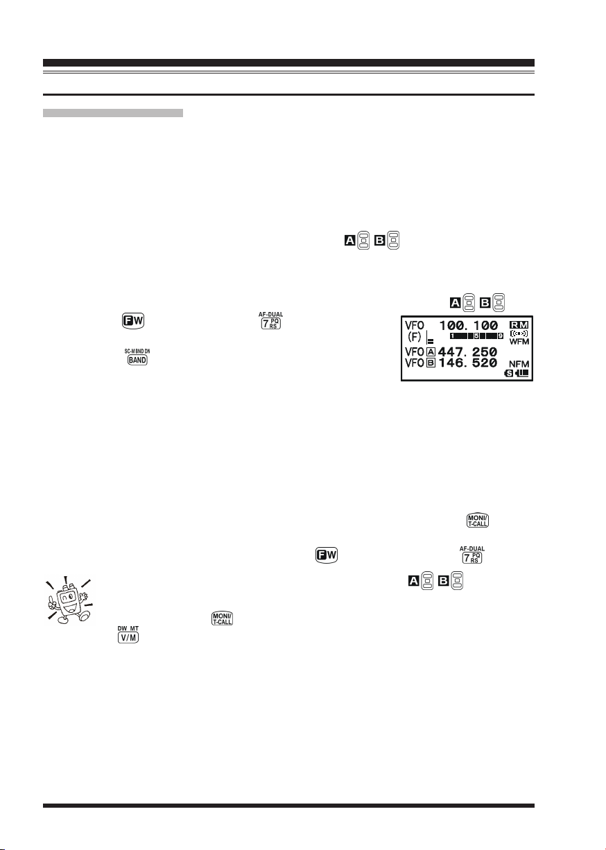
anytime. The “Main” band is selected by pressing the / key as usual.
1. Set the VX-8R to the desired amateur band frequencies by the VFO or Memory channel selections on both “A-Band” and “B-Band”.
2. Select the “Main” Band you wish to use for transmit by pressing the / key.
3. Press the key, then press the key to activate the
AF Dual operation.
4. Press the key to toggle the receiver between “AM
broadcast” and “FM broadcast”.
5. Rotate the DIAL knob to tune the desired Broadcast station.
6. When a signal is received in the amateur band, the amateur band audio is output to the
speaker. The AM or FM Broadcast station will no longer be heard. Two seconds after
the amateur band signal drops, the AF-Dual Operation is resumed and the AM or FM
Broadcast station will be heard from the speaker, while the amateur band frequencies
are monitored. You may change the default resume time (two seconds) via Set Mode
77: RX AF DUAL77: RX AF DUAL
Item
77: RX AF DUAL. See the box on the next page.
77: RX AF DUAL77: RX AF DUAL
7. You may monitor the amateur band frequencies forcibly by holding the switch.
8. Press the PTT switch to transmit on the “Main” band.
9. To disable the AF-Dual Operation, press the key, followed by the key.
1) You may change the “Main” band by pressing the / key.
2) You may change the “Main” band frequency by rotating the DIAL knob
while pressing the switch.
3) When the key is pressed, only the AM and FM Broadcast station memories are
recalled.
VX-8R OPERATING MANUAL24
OPERATION
AM AND FM BROADCAST RECEPTION
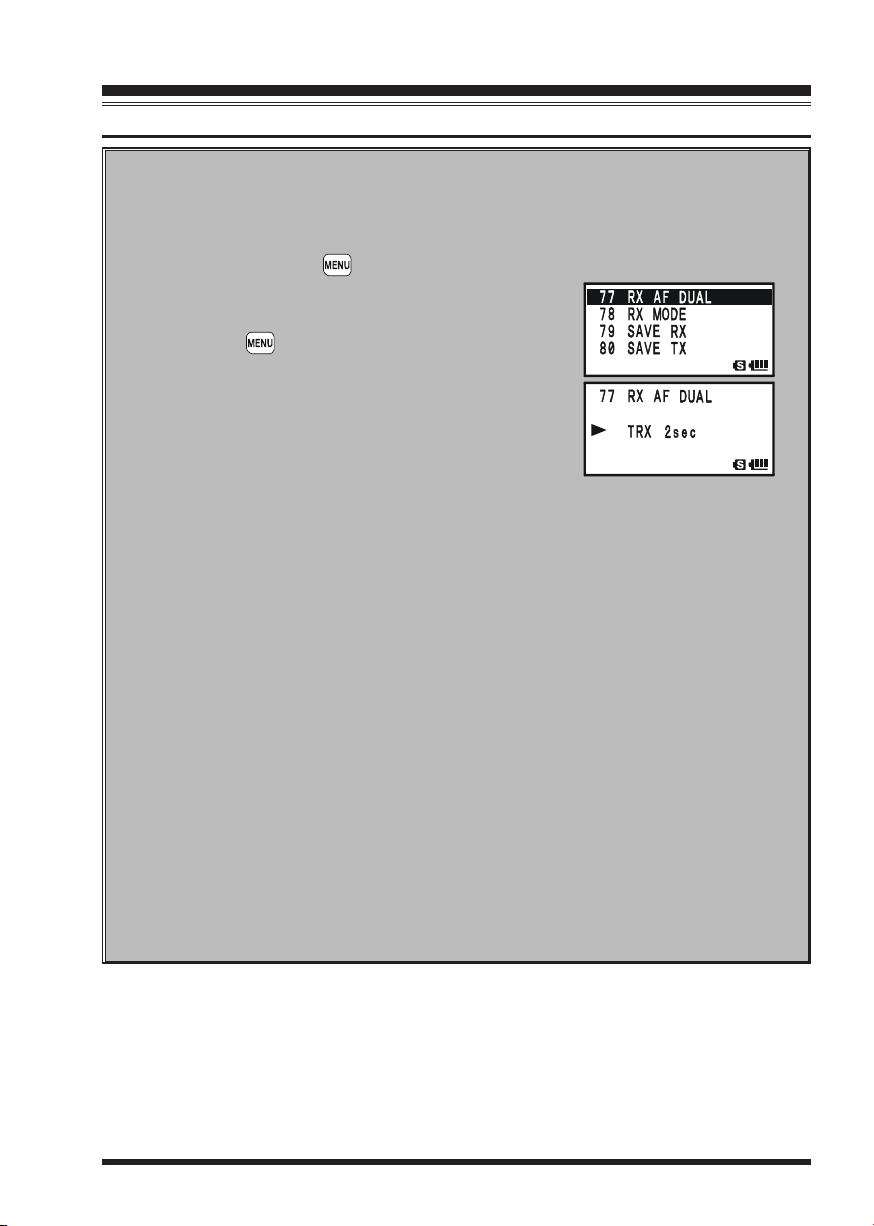
SETTING THE AF-DUAL RESUME MODE
The VX-8R allows you to select the resume mode of the AF-Dual Operation
when a signal is received in the amateur band.
1. Press and hold the key for one second to enter the Set Mode.
2. Rotate the DIAL knob to select Set Mode Item
RX AF DUALRX AF DUAL
RX AF DUAL.
RX AF DUALRX AF DUAL
3. Press the key briefly to enable selection of this
Menu Item.
4. Rotate the DIAL knob to select the desired resume
mode of the AF-Dual Operation:
TX 1sec - TX 10secTX 1sec - TX 10sec
TX 1sec - TX 10sec: Sets the period of time
TX 1sec - TX 10secTX 1sec - TX 10sec
after you transmit an
amateur signal before the AM or FM Broadcast station will be heard from the speaker, and the AFDual Operation is resumed. However, if a signal is
received in the amateur band, the AF-Dual Operation will halt on the amateur band frequency and
the AF-Dual Operation does not resume.
TRX 1sec - TXR 10secTRX 1sec - TXR 10sec
TRX 1sec - TXR 10sec: When the selected time passes after the amateur
TRX 1sec - TXR 10secTRX 1sec - TXR 10sec
band signal drops or transmission is over, the AM
or FM Broadcast station will be heard from the
speaker and the AF-Dual Operation is resumed.
HOLDHOLD
HOLD: When a signal is received in the amateur band or if
HOLDHOLD
you transmit on the amateur band, the AF-Dual Operation will halt on the amateur band frequency (the
AF-Dual Operation does not resume.). You must
manually re-initiate the AF-Dual Operation, if you
wish to resume.
5. When you have made your selection, press the PTT switch to save the new
setting and resume normal mode.
77:77:
77:
77:77:
VX-8R OPERATING MANUAL 25
ADVANCED OPERATION
Now that you mastered the basics of VX-8R operation, let’s learn more about some of the
really neat features.
KEYBOARD LOCKING
In order to prevent accidental frequency change or inadvertent transmission, various keys
and switches may be locked out. The possible lockout combinations are:
KEYKEY
KEY: Just the front panel keys are locked out
KEYKEY
DIALDIAL
DIAL: Just the top panel DIAL is locked out
DIALDIAL
KEY&DIALKEY&DIAL
KEY&DIAL: Both the DIAL knob and Keys are locked out
KEY&DIALKEY&DIAL
PTTPTT
PTT: The PTT switch is locked (TX not possible)
PTTPTT
KEY&PTTKEY&PTT
KEY&PTT: Both the keys and PTT switch are locked out
KEY&PTTKEY&PTT
DIAL&PTTDIAL&PTT
DIAL&PTT: Both the DIAL knob and PTT switch are locked out
DIAL&PTTDIAL&PTT
ALLALL
ALL: All of the above are locked out
ALLALL
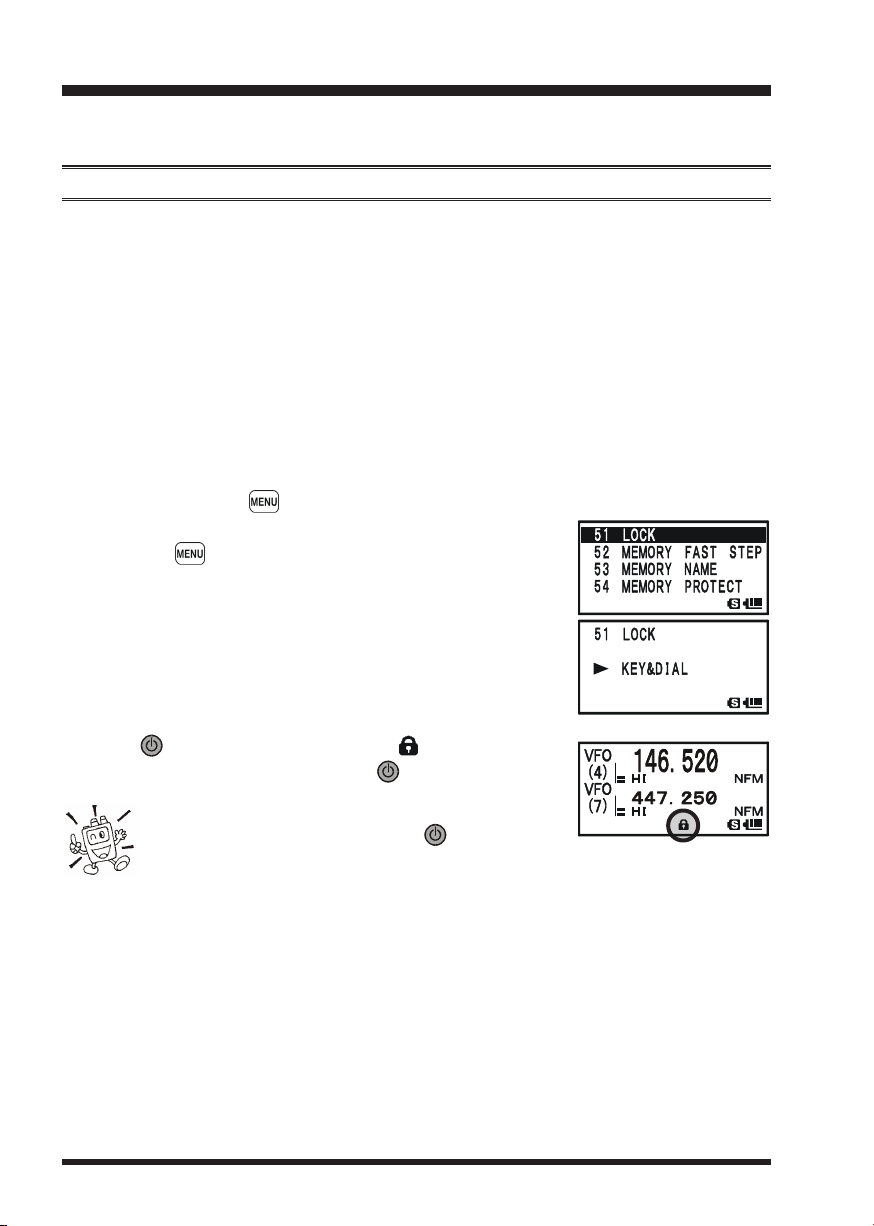
To lock out some or all of the keys:
1. Press and hold the key for one second to enter the Set Mode.
2. Rotate the DIAL knob to select Set Mode Item
3. Press the key briefly to enable selection of this Menu
Item.
4. Rotate the DIAL knob to choose between one of the locking schemes as outlined above.
5. When you have made your selection, press the PTT switch
to save the new setting and resume normal operation.
51: LOCK51: LOCK
51: LOCK.
51: LOCK51: LOCK
To activate the locking feature:
Press the (PWR) switch briefly. The “ ” icon will appear
on the LCD. To cancel locking, press the (PWR) switch again.
Even when “ALL” keys have been locked out, one
key actually is not locked out: the (PWR) switch
remains available so you can unlock your keypad when you want to!
VX-8R OPERATING MANUAL26
ADVANCED OPERATION
ADJUSTING THE KEYPAD BEEPER VOLUME LEVEL
A keypad beeper provides useful audible feed back whenever a key button is pressed. The
keypad beeper level changes according to the receiver audio volume level setting. However, you may adjust the volume balance between the receiving audio and keypad beeper
using Set Mode Item
1. Press and hold the key for one second to enter the Set Mode.
2. Rotate the DIAL knob to select Set Mode Item
LEVELLEVEL
LEVEL.
LEVELLEVEL
3. Press the key briefly to enable selection of this Set Mode
Item.
4. Rotate the DIAL knob to select the desired level.
5. When you have made your choice, press the PTT switch to
save the new setting and return to normal operation.
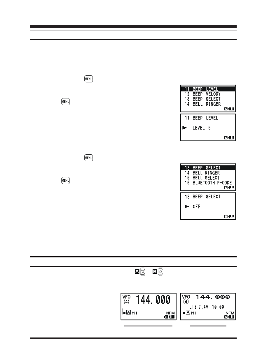
Additionally, if you want to turn the beep off:
1. Press and hold the key for one second to enter the Set Mode.
2. Rotate the DIAL knob to select Set Mode Item
SELECTSELECT
SELECT.
SELECTSELECT
3. Press the key briefly to enable selection of this Set Mode
Item.
4. Rotate the DIAL knob to change the setting to “
5. When you have made your choice, press the PTT switch to
save the new setting and return to normal operation.
6. If you wish to re-enable the Beeper, just repeat the above
procedure, rotating the DIAL knob to select “
above.
KEYKEY
KEY: The beeper sounds when you press any key.
KEYKEY
KEY & SCANKEY & SCAN
KEY & SCAN: The beeper sounds when you press a key or when the scanner stops.
KEY & SCANKEY & SCAN
11: BEEP LEVEL11: BEEP LEVEL
11: BEEP LEVEL.
11: BEEP LEVEL11: BEEP LEVEL
11: BEEP11: BEEP
11: BEEP
11: BEEP11: BEEP
13: BEEP13: BEEP
13: BEEP
13: BEEP13: BEEP
OFFOFF
OFF”.
OFFOFF
KEYKEY
KEY” or “
KEYKEY
KEY & SCANKEY & SCAN
KEY & SCAN” in step “4”
KEY & SCANKEY & SCAN
SETTING THE FREQUENCY DISPLAY IMAGE SIZE
When operating in “Mono” band, pressing the or key, causes the LCD to “toggle”
between display of double-size characters and large characters. However, this feature
does not work during Dual Receive operation, as two frequencies are displayed in that
instance.
DOUBLE-SIZE CHARACTERS
VX-8R OPERATING MANUAL 27
LARGE CHARACTERS
ADVANCED OPERATION
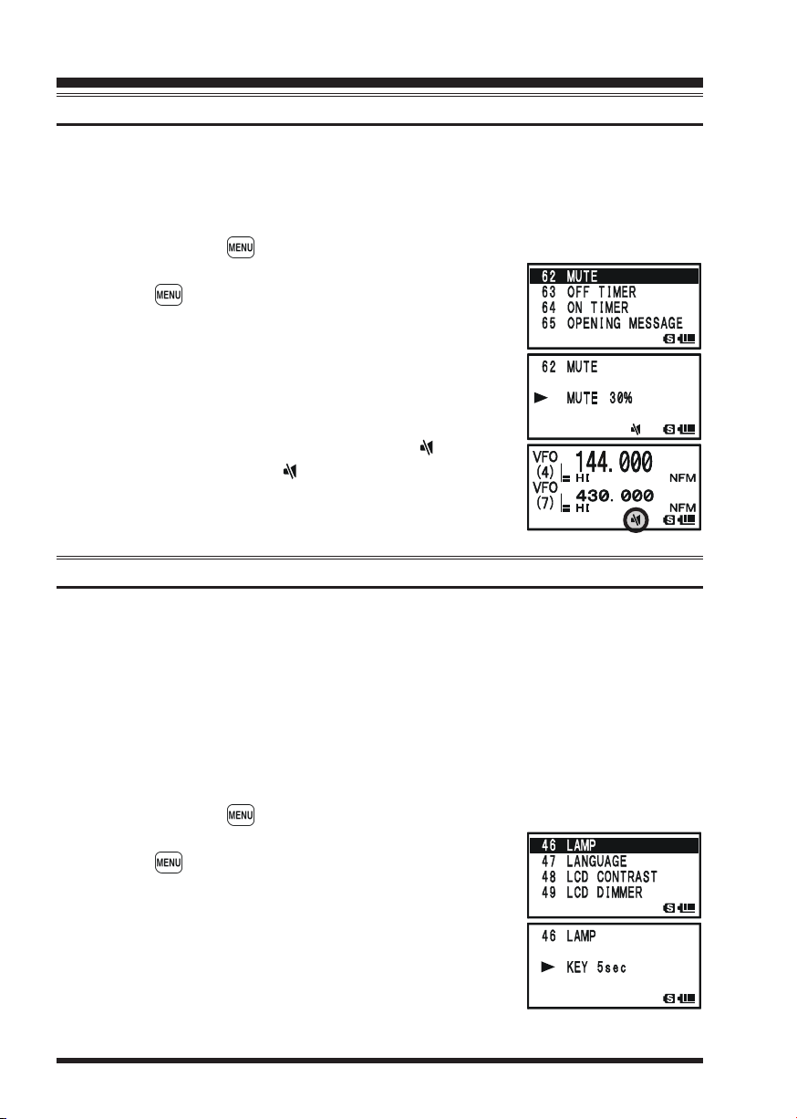
AUDIO MUTING
The Audio Mute feature is useful in situations where it would be helpful to reduce the
audio level of the “Receive Only” band (Small character display) whenever you receive a
signal on the “Main” band (Large character display) during Dual Receive operation.
To activate the Audio Mute feature:
1. Press and hold the key for one second to enter the Set Mode.
2. Rotate the DIAL knob to select Set Mode Item
3. Press the key briefly to enable selection of this Set Mode
Item.
4. Rotate the DIAL knob to select the desired muting level
MUTE 30%MUTE 30%
(
MUTE 30%,
MUTE 30%MUTE 30%
5. When you have made your choice, press the PTT switch to
save the new setting and return to normal operation.
When the Audio Mute feature is activated, the “ ” icon will
appear on the display, and the “ ” icon blinks while muting the
“Receive Only” band audio.
MUTE 50%MUTE 50%
MUTE 50%,
MUTE 50%MUTE 50%
MUTE 100%MUTE 100%
MUTE 100%, or
MUTE 100%MUTE 100%
KEYPAD/LCD ILLUMINATION
Your VX-8R includes a reddish illumination lamp which aids in nighttime operation. The
red illumination yields clear viewing of the display in a dark environment, with minimal
degradation of your night vision. Three options for activating the lamp are provided:
62: MUTE62: MUTE
62: MUTE.
62: MUTE62: MUTE
OFFOFF
OFF).
OFFOFF
KEY 2secKEY 2sec
KEY 2sec -
KEY 2secKEY 2sec
CONTINUOUSCONTINUOUS
CONTINUOUS: Illuminates the Keypad/LCD continuously.
CONTINUOUSCONTINUOUS
OFFOFF
OFF: Disables the Keypad/LCD lamp.
OFFOFF
KEY 10secKEY 10sec
KEY 10sec: Illuminates the Keypad/LCD for the selected illumination
KEY 10secKEY 10sec
time when any key is pressed.
Here is the procedure for setting up the Lamp mode:
1. Press and hold the key for one second to enter the Set Mode.
2. Rotate the DIAL knob to select Set Mode Item
3. Press the key briefly to enable selection of this Set Mode
Item.
4. Rotate the DIAL knob to select one of the three modes described above.
5. When you have made your choice, press the PTT switch to
save the new setting and return to normal operation.
46: LAMP46: LAMP
46: LAMP.
46: LAMP46: LAMP
VX-8R OPERATING MANUAL28

ADVANCED OPERATION
CHANGING THE CHANNEL STEPS
The VX-8R’s frequency synthesizer provides the option of utilizing tuning steps of 5, 6.25,
8.33, 9, 10, 12.5, 15, 20, 25, 50, 100, and 200 kHz per step. The VX-8R is set up at the
factory with different default steps for each operating band which are probably satisfactory
for most operation. However, if you need to change the channel step increments, the procedure to do so is very easy.
1. Press the key, then press the key on the left side of the radio. This provides a
“Short-cut” to Set Mode Item
2. Rotate the DIAL knob to select the desired step size.
3. Press the PTT switch to save the new setting and return to
normal operation.
1) 9 kHz steps are available only when receiving on the BC band.
2) 8.33 kHz steps are available only when receiving on the Air band.
3) While operating on the BC band, you may only select channel steps of 9
kHz or 10 kHz; the other step selections are disabled.
4) 5 kHz steps are not available for use on 250 - 300 MHz, nor above 580 MHz.
CHANGING THE RECEIVING MODE
The VX-8R provides for automatic mode changing when
the radio is tuned to different operating frequencies. However, should an unusual receiving situation arise in which
you need to change to a different receiving mode, just press
the key. The receiving modes available are:
96: STEP FREQUENCY96: STEP FREQUENCY
96: STEP FREQUENCY.
96: STEP FREQUENCY96: STEP FREQUENCY
AUTOAUTO
AUTO: The receive mode is automatically set accord-
AUTOAUTO
ing to the default values for the selected frequency range
NFMNFM
NFM: Narrow-bandwidth FM (used for voice communication)
NFMNFM
WFMWFM
WFM: Wide-bandwidth FM (used for high-fidelity broadcasting)
WFMWFM
AMAM
AM: Amplitude Modulation
AMAM
1) The “WFM” mode cannot be selected on the “A-Band”.
2) Unless you have a compelling reason to do so, leave the Automatic Mode
Selection feature on in order to save time and trouble when changing bands.
If you make a mode change for a particular frequency or station, you can always store
that one channel into memory, as the mode setting will be memorized along with the
frequency information.
VX-8R OPERATING MANUAL 29

ADVANCED OPERATION
SQL S-METER
A special SQL (Squelch) S-meter feature is provided on this radio. This feature allows
you to set the squelch so only signals exceeding a certain S-meter level will open the
squelch.
To set up the S-meter squelch feature for operation, use the following procedure:
1. Press and hold the key for one second to enter the Set Mode.
2. Rotate the DIAL knob to select Set Mode Item
METERMETER
METER.
METERMETER
3. Press the key briefly to enable selection of this Set Mode
Item.
4. Rotate the DIAL knob to select the desired signal strength
level for the squelch threshold (
5. When you have made your choice, press the PTT switch to
save the new setting and return to normal operation.
1) When the SQL S-meter is activated, the S-meter segment corresponding to
the squelch threshold which was set by step 4 above will blink.
2) The receiver’s squelch will open based on the higher of the levels set by the
Noise Squelch or the S-meter Squelch system.
For example:
a) If the Noise Squelch (SQL control) is set so that signals at a level of “S-3” will open
the squelch, but the SQL S-meter (Set Mode Item 93) is set to “LEVEL 5,” the squelch
will only open on signals which are “S5” or stronger on the S-meter.
b) If the SQL S-meter is set to “S3,” but the Noise Squelch is set to a high level which
will only pass signals which are Full Scale on the S-meter, the squelch will only open on
signals which are Full Scale on the S-meter. In this case, the Noise Squelch overrides
the action of the S-meter Squelch.
LEVEL1LEVEL1
LEVEL1 -
LEVEL1LEVEL1
93: SQL S-93: SQL S-
93: SQL S-
93: SQL S-93: SQL S-
LEVEL9LEVEL9
LEVEL9 or
LEVEL9LEVEL9
OFFOFF
OFF).
OFFOFF
VX-8R OPERATING MANUAL30

REPEATER OPERATION
GENERAL
Repeater stations, usually located on mountaintops or other high locations, provide a dramatic extension of the communication range for low-powered hand-held or mobile transceivers. The VX-8R includes a number of features, which make repeater operation simple
and enjoyable.
REPEATER SHIFTS
Your VX-8R has been configured, at the factory, for the repeater shifts customary in your
country. For the 50 MHz band, this usually will be 1 MHz, while the 144 MHz shift will
be 600 kHz; on 70 cm, the shift may be 1.6 MHz, 7.6 MHz, or 5 MHz (USA version).
Depending on the part of the band in which you are operating, the repeater shift may be
either downward ( ) or upward ( ),
and one of these icons will appear at
the bottom of the LCD when repeater
shifts have been enabled.
AUTOMATIC REPEATER SHIFT (ARS
)
The VX-8R provides a convenient Automatic Repeater Shift feature, which causes the
appropriate repeater shift to be automatically applied whenever you tune into the designated repeater sub-bands in your country. These sub-bands are shown below.
If the ARS feature does not appear to be working, you may have accidentally disabled it.
To re-enable ARS:
1. Press and hold the key for one second to enter the Set Mode.
7474
2. Rotate the DIAL knob to select Set Mode Item
: RPT ARS: RPT ARS
74
: RPT ARS.
7474
: RPT ARS: RPT ARS
3. Press the key briefly to enable selection of this Set Mode
Item.
4. Rotate the DIAL knob to select “
ONON
ON”(to enable Automatic
ONON
Repeater Shift).
5. When you have made your choice, press the PTT switch
to save the new setting and return to normal operation.
ARS-Repeater Subbands
145.1 145.5
145.6 145.8
Versi on A
433.00 434.60433.40 435.00
2-m
Versi on A
146.0 146.4 147.0 147.6 148.0
146.6
70-cm
147.4
439.45438.20
Euro Version 1
Euro Version 2
European Version
440.0 445.0 450.0
VX-8R OPERATING MANUAL 31

REPEATER OPERATION
MANUAL REPEATER SHIFT ACTIVATION
If the ARS feature has been disabled, or if you need to set a repeater shift direction other
than that established by the ARS, you may set the direction of the repeater shift manually.
To do this:
1. Press the key, then press the key. This provides a “Short-cut” to Set Mode
75: RPE SHIFT75: RPE SHIFT
Item
75: RPE SHIFT.
75: RPE SHIFT75: RPE SHIFT
2. Rotate the DIAL knob to select the desired shift among
–RPT–RPT
“
–RPT,” “
–RPT–RPT
3. Press the PTT switch to save the new setting and exit to
normal operation.
CHANGING THE DEFAULT REPEATER SHIFTS
If you travel to a different region, you may need to change the default repeater shift, to
ensure compatibility with local operating requirements.
To do this, follow the procedure below:
1. Press and hold the key for one second to enter the Set Mode.
2. Rotate the DIAL knob to select Set Mode Item
SHIFT FREQSHIFT FREQ
SHIFT FREQ.
SHIFT FREQSHIFT FREQ
3. Press the key briefly to enable selection of this Set Mode
Item.
4. Rotate the DIAL knob to select the new repeater shift magnitude.
5. Press the PTT switch to save the new setting and return to
normal operation.
+RPT+RPT
+RPT,” and “
+RPT+RPT
SIMPLEXSIMPLEX
SIMPLEX.”
SIMPLEXSIMPLEX
76: RPT76: RPT
76: RPT
76: RPT76: RPT
If you just have one “odd” split that you need to program, don’t change the
default repeater shift! Enter the transmit and receive frequencies separately,
as shown on page 48.
VX-8R OPERATING MANUAL32

REPEATER OPERATION
)
CHECKING THE REPEATER UPLINK (INPUT
It often is helpful to be able to check the uplink (input) frequency of a repeater, to see if the
calling station is within direct (“Simplex”) range.
To do this, just press the key. You’ll notice that the display has shifted to the repeater
uplink frequency. Press the key again to cause operation to
return to normal monitoring of the repeater downlink (output)
frequency. While you are listening on the input frequency of the
repeater using the key, the repeater offset icon (“ ” or ”)
will blink.
The configuration of key may be set either to “RV” (for checking the
input frequency of a repeater, or “HM” (for instant switching to the “Home”
channel for the band you are operating on). To change the configuration of
key, use Set Mode Item 39: HOME/REVERSE. See page 148.
F
REQUENCY
VX-8R OPERATING MANUAL 33

CTCSS/DCS/EPCS OPERATION
CTCSS OPERATION
Many repeater systems require that a very-low-frequency audio tone be superimposed on
your FM carrier in order to activate the repeater. This helps prevent false activation of the
repeater by radar or spurious signals from other transmitters. This tone system, called
“CTCSS” (Continuous Tone Coded Squelch System), is included in your VX-8R, and is
very easy to activate.
CTCSS setup involves two actions: setting the Tone Frequency and then setting the Tone Mode. These functions are set up using Set Mode Items 94:
SQL TYP and 98: TONE FREQUENCY.
1. Press the key, then press the key. This provides a “Short-cut” to Set Mode
95: SQL TYPE95: SQL TYPE
Item
95: SQL TYPE.
95: SQL TYPE95: SQL TYPE
2. Rotate the DIAL knob so that “
play. This activates the CTCSS Encoder.
3. Rotation of the DIAL knob one more “click” in step “2”
above will also activate the “
Tone Squelch system is active, which mutes your VX-8R’s receiver until it receives a
call from another radio sending out a matching CTCSS tone. This can helpful in a
high RF congested location by keeping your radio quiet until a call is received from a
specific station with a matching CTCSS tone.
TONETONE
TONE” appears on the dis-
TONETONE
TSQLTSQL
TSQL” decode function. When “
TSQLTSQL
TSQLTSQL
TSQL” is displayed, the
TSQLTSQL
You may notice an additional “
the DIAL knob in step 3 above. We’ll discuss the Digital Code Squelch system shortly.
You may notice “
DIAL knob in step 3 above. When the Reverse Tone Squelch system is active, the VX-8R’s receiver is muted when it receives a call from a radio sending a matching CTCSS tone. The “
when the Reverse Tone Squelch system is activated.
You may notice “
DIAL knob in step 3 above, this means the user programmed Reverse CTCSS
Decoder will mute your VX-8R’s receiver when it receives a call from a
radio sending a CTCSS tone matching your programmed tone (determine by
Set Mode Item
display when the Reverse CTCSS Decoder is activated.
You may notice “
you rotate the DIAL knob in step 3 above. These appear when the “Enhanced
Paging & Code Squelch” and the “Message Feature” are activated. We’ll
discuss these functions later.
REV TONEREV TONE
REV TONE” indication on the display while you rotate the
REV TONEREV TONE
PR FREQPR FREQ
PR FREQ” indication on the display while you rotate the
PR FREQPR FREQ
70: PR FREQUENCY70: PR FREQUENCY
70: PR FREQUENCY). The “
70: PR FREQUENCY70: PR FREQUENCY
PAGERPAGER
PAGER” and “
PAGERPAGER
DCSDCS
DCS” indication appearing while you rotate
DCSDCS
RTNRTN
RTN” icon will appear on the display
RTNRTN
PRPR
PR” icon will appear on the
PRPR
MESSAGEMESSAGE
MESSAGE” indication on the display while
MESSAGEMESSAGE
VX-8R OPERATING MANUAL34

CTCSS/DCS/EPCS OPERATION
CTCSS OPERATION
4. When you have made your selection of the CTCSS tone mode, press the key to
save the new setting and exit to normal operation.
5. Press the key, then press the key. This provides a “Short-cut” to Set Mode
99: TONE FREQUENCY99: TONE FREQUENCY
Item
99: TONE FREQUENCY.
99: TONE FREQUENCY99: TONE FREQUENCY
6. Rotate the DIAL knob until the display indicates the frequency of the CTCSS tone that you need to send on your
transmission (ask the repeater owner/operator if you don’t
know the tone frequency).
7. When you have made your selection, press the key briefly to save the new setting
and exit to normal operation. This is different from the usual method of restoring
normal operation, and it applies only to the configuration of the CTCSS/DCS frequencies.
1) The repeater may or may not
re-transmit a CTCSS tone - some
systems just use CTCSS to control
access to the repeater, but do not pass it along
when transmitting. If the S-Meter deflects,
but you cannot hear the audio, repeat steps
“1” through “4” above, but rotate the DIAL
so that “TSQ” disappears - this will allow
you to hear all traffic on the channel being
CTCSS TONE FREQUENCY (Hz
67.0 69.3 71.9 74.4 77.0 79.7
82.5 85.4 88.5 91.5 94.8 97.4
100.0 103.5 107.2 110.9 114.8 118.8
123.0 127.3 131.8 136.5 141.3 146.2
151.4 156.7 159.8 162.2 165.5 167.9
171.3 173.8 177.3 179.9 183.5 186.2
189.9 192.8 196.6 199.5 203.5 206.5
210.7 218.1 225.7 229.1 233.6 241.8
250.3 254.1 – – – –
)
received.
2) During CTCSS operation, you may set up the VX-8R so a ringing “bell” sound alerts
you to an incoming call. See page 42 for details.
VX-8R OPERATING MANUAL 35

CTCSS/DCS/EPCS OPERATION
DCS OPERATION
Another form of tone access control is Digital Code Squelch, or DCS. It is a newer, more
advanced tone system which generally provides more immunity from false paging than
does CTCSS. The DCS Encoder/Decoder is built into your VX-8R, and operation is very
similar to that just described for CTCSS. Your repeater system may be configured for
DCS. The DCS Squelch may be quite useful in Simplex operation if your friends use
transceivers equipped with this advanced feature.
Note: Just as in CTCSS operation, DCS requires that you set the Tone Mode to DCS
and that you select a DCS code.
1. Press the key, then press the key. This provides a
“Short-cut” to Set Mode Item
2. Rotate the DIAL knob until “
this activates the DCS Encoder/Decoder.
3. Press the key to save the new setting and exit to normal operation.
4. Press the key, then press the key. This provides a
“Short-cut” to Set Mode Item
5. Rotate the DIAL knob to select the desired DCS Code (a three-digit number). Ask the
repeater owner/operator if you don’t know DCS Code; if you are working simplex,
just set up the DCS Code to be the same as that used by your friends.
6. When you have made your selection, press the key to save the new settings and
exit to normal operation.
95: SQL TYPE95: SQL TYPE
95: SQL TYPE.
95: SQL TYPE95: SQL TYPE
DCSDCS
DCS” appears on the display;
DCSDCS
26: DCS CODE26: DCS CODE
26: DCS CODE.
26: DCS CODE26: DCS CODE
Remember that the DCS is an
Encode/Decode system, so your
receiver will remain muted until
a matching DCS code is received on an incoming transmission. Switch the DCS off
when you’re just tuning around the band!
DCS CODE
023 025 026 031 032 036 043 047 051 053
054 065 071 072 073 074 114 115 116 122
125 131 132 134 143 145 152 155 156 162
165 172 174 205 212 223 225 226 243 244
245 246 251 252 255 261 263 265 266 271
274 306 311 315 325 331 332 343 346 351
356 364 365 371 411 412 413 423 431 432
445 446 452 454 455 462 464 465 466 503
506 516 523 526 532 546 565 606 612 624
627 631 632 654 662 664 703 712 723 731
732 734 743 754 – – – – – –
VX-8R OPERATING MANUAL36

CTCSS/DCS/EPCS OPERATION
DCS OPERATION
DCS CODE INVERSION
The DCS system was first introduced in the commercial LMR (Land Mobile Radio) service, where it is now in widespread use. DCS is sometime referred to by its different
proprietary names, such as DPL® (Digital Private Line®, a registered trademark of Motorola,
Inc.).
DCS uses a codeword consisting of a 23-bit frame, transmitted (sub audible) at a data rate
of 134.4 bps (bit/sec). Occasionally, signal inversion can result in the complement of a
code being sent or received. This prevents the receiver’s squelch from opening with DCS
enabled, as the decoded bit sequence would not match that selected for operation.
Typical situations that might cause inversion to occur are:
Connection of an external receiver preamplifier.
Operating through a repeater.
Connection of an external linear amplifier.
Note that code inversion does not mean that any of the above listed equipment is defective!
In certain amplifier configurations, the output signal (phase) is inverted from the input. Small
signal or power amplifiers having an odd number (1, 3, 5, etc.) of amplification stages may
result in inversion of a transmitted or received DCS code. While under most circumstances
this should not occur (amplifier designs and industry standards take this into account), if you
find that your receiver squelch does not open when both you and the other station are using a
common DCS code, you or the other station (but not both) can try the following:
1. Press and hold the key for one second to enter the Set Mode.
2. Rotate the DIAL knob to select Set Mode Item
INVERSIONINVERSION
INVERSION.
INVERSIONINVERSION
3. Press the key briefly to enable adjustment of this Set
Mode Item.
4. Rotate the DIAL knob to select one of the following modes:
RX-NORMAL, TX-NORMALRX-NORMAL, TX-NORMAL
RX-NORMAL, TX-NORMAL:
RX-NORMAL, TX-NORMALRX-NORMAL, TX-NORMAL
Receive and transmit the Normal DCS Tone.
RX-INVERT, TX-NORMALRX-INVERT, TX-NORMAL
RX-INVERT, TX-NORMAL:
RX-INVERT, TX-NORMALRX-INVERT, TX-NORMAL
Receive the Inverted DCS Tone and transmit the Normal DCS Tone.
RX-BOTH, TX-NORMALRX-BOTH, TX-NORMAL
RX-BOTH, TX-NORMAL:
RX-BOTH, TX-NORMALRX-BOTH, TX-NORMAL
Receive both Normal and Inverted DCS Tones and transmit the Normal DCS
Tone.
RX-NORMAL, TX-INVERTRX-NORMAL, TX-INVERT
RX-NORMAL, TX-INVERT:
RX-NORMAL, TX-INVERTRX-NORMAL, TX-INVERT
Receive the Normal DCS Tone and transmit the Inverted DCS Tone.
27: DCS27: DCS
27: DCS
27: DCS27: DCS
VX-8R OPERATING MANUAL 37

CTCSS/DCS/EPCS OPERATION
DCS OPERATION
RX-INVERT, TX-INVERTRX-INVERT, TX-INVERT
RX-INVERT, TX-INVERT:
RX-INVERT, TX-INVERTRX-INVERT, TX-INVERT
Receive and transmit the Inverted DCS Tone.
RX-BOTH, TX-INVERTRX-BOTH, TX-INVERT
RX-BOTH, TX-INVERT:
RX-BOTH, TX-INVERTRX-BOTH, TX-INVERT
Receive both Normal and Inverted DCS Tones and transmit the Inverted DCS
Tone.
5. When you have made your selection, press the PTT switch, to save the new settings
and exit to normal operation.
This is different from the usual method of restoring normal operation, and it applies only
to the configuration of the CTCSS/DCS frequencies. Remember to restore the default
setting “
R-N.T-NR-N.T-N
R-N.T-N” (Receive and transmit the Normal DCS Tone) when done.
R-N.T-NR-N.T-N
VX-8R OPERATING MANUAL38

CTCSS/DCS/EPCS OPERATION
TONE SEARCH SCANNING
In operating situations where you don’t know the CTCSS or DCS tone being used by
another station, you can command the radio to listen to the incoming signal and scan in
search of the tone being used. Two things must be remembered in this regard:
You must be sure that your repeater uses the same tone type (CTCSS vs. DCS).
Some repeaters do not pass the CTCSS tone; you may have to listen to the station
transmitting on the repeater uplink (input) frequency in order to allow Tone Search
Scanning to work.
To scan for the tone in use:
1. Set the radio up for either CTCSS or DCS Decoder operation (see the previous discussion). In the case of CTCSS,
TSQTSQ
“
TSQ” will appear on the display;
TSQTSQ
in the case of DCS, “
appear on the display.
2. Press the key, then press the
key to recall the Set Mode
99: TONE FREQUENCY99: TONE FREQUENCY
Item
99: TONE FREQUENCY
99: TONE FREQUENCY99: TONE FREQUENCY
when CTCSS is selected, or Menu
26: DCS CODE26: DCS CODE
Item
26: DCS CODE during DCS operation.
26: DCS CODE26: DCS CODE
3. Press the key to enable adjustment of the selected Set Mode Item.
4. Press and hold in the key, the “
key to start scanning for the incoming CTCSS or DCS tone/code.
5. When the radio detects the correct tone or code, it will halt on that tone/code, and
audio will be allowed to pass. Press the key to lock in that tone/code, then press
the key to exit to normal operation.
DCSDCS
DCS” will
DCSDCS
TONE SEARCHTONE SEARCH
TONE SEARCH” notation will appear, release the
TONE SEARCHTONE SEARCH
If the Tone Scan feature does not detect a tone or code, it will continue to
scan indefinitely. When this happens, it may be that the other station is not
sending any tone. You can press the PTT switch to halt the scan at any time.
You can also press the key during Tone Scanning to listen to the (muted) signal from
the other station. When you release the key, Tone Scanning will resume after about a
second.
Tone Scanning works either in the VFO or Memory modes.
VX-8R OPERATING MANUAL 39

CTCSS/DCS/EPCS OPERATION
EPCS (ENHANCED PAGING & CODE SQUELCH
The VX-8R includes an Enhanced CTCSS tone encoder/decoder and a dedicated microprocessor providing paging and selective calling features. This allows you to place a call
to a specific station (Paging), and to receive calls of your choice directed only to you
(Code Squelch).
The paging and code squelch systems use two pairs of (alternately switched) CTCSS
tones which are stored in the pager memories. Basically, your receiver remains silent until
it receives the CTCSS tone pair that matches those stored in the Receiving Pager Memory.
The squelch then opens so the caller is heard, and the paging ringer immediately sounds,
if activated. When you close the PTT switch to transmit, the CTCSS tone pair that is
stored in the Transmitting Pager Memory will be transmitted automatically.
On the paged radio, the Code Squelch will close automatically after the incoming page
ends. Meanwhile, on the paging radio, the Enhanced Paging and Code Squelch system
will be disabled after the PTT switch is released after the paging transmission. You may
re-activate the Enhanced Paging and Code Squelch system again.
)
STORING THE CTCSS TONE PAIRS FOR EPCS OPERATION
1. Press and hold the key for one second to enter the Set Mode.
2. Rotate the DIAL knob to select Set
Mode Item
for the Receiving CTCSS Tone
Pair or Set Mode Item
CODE-TXCODE-TX
CODE-TX for the Transmitting CTCSS Tone Pair.
CODE-TXCODE-TX
3. Press the key briefly to enable adjustment of this Set
Mode Item.
4. Rotate the DIAL knob to set the CTCSS Tone number which
corresponds to the first tone of the CTCSS Tone Pair.
5. Press the key (“¾” icon moves to the right), then rotate the DIAL knob to set the CTCSS Tone number, which
corresponds to the second tone of the CTCSS Tone Pair.
6. Press the PTT switch to save the new setting and exit to
normal operation.
67: PAGER CODE-RX67: PAGER CODE-RX
67: PAGER CODE-RX
67: PAGER CODE-RX67: PAGER CODE-RX
68: PAGER68: PAGER
68: PAGER
68: PAGER68: PAGER
The VX-8R does not recognize the order of the 1st
tone and the 2nd tone. In other words, for example,
the VX-8R considers both CTCSS pairs “10, 35”
and “35, 10” to be identical.
VX-8R OPERATING MANUAL40

CTCSS/DCS/EPCS OPERATION
EPCS (ENHANCED PAGING & CODE SQUELCH
)
ACTIVATING THE ENHANCED PAGING & CODE SQUELCH SYSTEM
1. Press the key, then press the key. This provides a “Short-cut” to Set Mode
95: SQL TYPE95: SQL TYPE
Item
95: SQL TYPE.
95: SQL TYPE95: SQL TYPE
2. Rotate the DIAL knob until “
play; this activates the Enhanced Paging & Code Squelch.
3. Press the PTT switch to save the new setting and activate
the Enhanced Paging & Code Squelch.
To disable the Enhanced Paging & Code Squelch, just repeat the above procedure, rotate
the DIAL knob to select “
When the Enhanced Paging & Code Squelch feature is activated, the “
PAGPAG
PAG” notation will appear on the display.
PAGPAG
During Enhanced Paging & Code Squelch operation, you may set up the VX-8R so that a ringing
“bell” sound alerts you when a call is coming in. See next page for details.
OFFOFF
OFF” in step 2 above.
OFFOFF
PAGERPAGER
PAGER” appears on the dis-
PAGERPAGER
PAGING ANSWER BACK
When you press the PTT switch to respond to a page call, the VX-8R transmits the same
CTCSS tone pair. This tone pair will open the Code Squelch of the calling station. If you
prefer, you can have the VX-8R respond to page calls automatically (“transpond”). To
enable this feature:
1. Press and hold the key for one second to enter the Set Mode.
2. Rotate the DIAL knob to select Set Mode Item
ANS-BACKANS-BACK
ANS-BACK.
ANS-BACKANS-BACK
3. Press the key briefly to enable adjustment of this Set
Mode Item.
4. Rotate the DIAL knob to select “
5. Press the PTT switch to save the new setting and exit to
normal operation.
The Paging Answer Back feature constitutes a form
of “remote control” operation that may be restricted to certain frequencies.
U.S. users should confirm the current status of §97.201(b) of the FCC’s rules
governing the Amateur service before utilizing this feature on the 144 MHz band.
ONON
ON”.
ONON
66: PAGER66: PAGER
66: PAGER
66: PAGER66: PAGER
VX-8R OPERATING MANUAL 41

CTCSS/DCS/EPCS OPERATION
CTCSS/DCS/EPCS BELL OPERATION
During CTCSS Decode, DCS, or EPCS operation, you may set up the VX-8R so that a
ringing “bell” sound alerts you that a call is coming in. Here is the procedure for activating
the CTCSS/DCS/EPCS Bell:
1. Set the operating frequency to the desired channel.
2. Set the transceiver up for CTCSS Decode (“Tone Squelch”), DCS, or EPCS operation, as described previously.
3. Press and hold the key for one second to enter the Set Mode.
4. Rotate the DIAL knob to select Set Mode Item
SELECTSELECT
SELECT.
SELECTSELECT
5. Press the key briefly to enable adjustment of this Set
Mode Item.
6. Rotate the DIAL knob to set the desired “bell” sound. The
BELLBELL
available choices are
BP3BP3
BP3, or
BP3BP3
Note: When User Beep (described later) does not register,
USER BP1USER BP1
USER BP1,
USER BP1USER BP1
7. Press the key briefly, then rotate the DIAL knob one
click counter-clockwise to select Set Mode Item
RINGERRINGER
RINGER.
RINGERRINGER
8. Press the key briefly to enable adjustment of this Menu
Item.
9. Rotate the DIAL knob to set the desired number of rings of
the Bell. The available choices are
or
10. Press the PTT switch briefly to save the new setting and exit to normal operation.
OFFOFF
OFF (disable the Bell function).
OFFOFF
USER BP2USER BP2
USER BP2, or
USER BP2USER BP2
CONTINUOUSCONTINUOUS
CONTINUOUS.
CONTINUOUSCONTINUOUS
USER BP1USER BP1
BELL,
USER BP1,
BELLBELL
USER BP1USER BP1
USER BP3USER BP3
USER BP3 does not appear.
USER BP3USER BP3
USER BP2USER BP2
USER BP2,
USER BP2USER BP2
1Time1Time
1Time through
1Time1Time
15: BELL15: BELL
15: BELL
15: BELL15: BELL
USERUSER
USER
USERUSER
14: BELL14: BELL
14: BELL
14: BELL14: BELL
20Times20Times
20Times
20Times20Times
When you are called by a station whose transceiver is sending a CTCSS tone, DCS code,
or CTCSS tone pair which matches that set into your Decoder, the Bell will ring in accordance with this programming.
When the CTCSS/DCS/EPCS Bell is activated, the “ ” icon
will appear in the display.
To disable the CTCSS/DCS/EPCS Bell function, select the setting of Set Mode Item
15: BELL SELECT15: BELL SELECT
15: BELL SELECT to “
15: BELL SELECT15: BELL SELECT
OFFOFF
OFF”.
OFFOFF
VX-8R OPERATING MANUAL42

CTCSS/DCS/EPCS OPERATION
CTCSS/DCS/EPCS BELL OPERATION
PROGRAMMING THE USER MELODY
Three User Beep Memories are provided, allowing you to create unique original beep
tone melodies.
Each User Beep Memory can store up to 64 steps with three octaves (“
1. Press and hold the key for one second to enter the Set Mode.
C1C1
C1 -
C1C1
12: BEEP12: BEEP
12: BEEP
12: BEEP12: BEEP
B3B3
B3.
B3B3
10ms10ms
10ms
10ms10ms
Step Operation Mode
Memory Slot Tone Length
2. Rotate the DIAL knob to select Set Mode Item
MELODYMELODY
MELODY.
MELODYMELODY
3. Press the key briefly to enable adjustment of this Set
Mode Item.
4. Rotate the DIAL knob to select the memory slot into which
you wish to store your programmed beep melody. Avail-
11
22
able selections are
melody will be displayed.
5. Press the key to enable programming the beep melody.
Press and hold the key for one second to clear any
previous beep melody, if desired.
6. Rotate the DIAL knob to select the first beep tone of the
User Beep Melody. Available selections are
7. Press the key, then rotate the DIAL knob to set the
length of the first beep tone. Available selections are
(10 msec) -
8. Press the key to accept the first beep tone of the User
Beep Melody.
9. If you make a mistake, press the key to back-space the
cursor, then re-enter the correct beep tone or length.
10. Repeat steps 6 - 9 until you have completed the User Beep
Melody.
11. When there is a beep tone, which you wish to delete, bring
the cursor to that beep tone using the / key, then
press the key repeatedly until the “
the “Operation Mode” slot turns into “
and hold in the key for one second to delete that beep
tone.
1,
11
2500ms2500ms
2500ms (2.5 sec).
2500ms2500ms
33
2, and
3. The previously stored beep
22
33
SELECTSELECT
SELECT” notation in
SELECTSELECT
DELETEDELETE
DELETE”. Now, press
DELETEDELETE
C1C1
C1” through “
C1C1
Beep Tone
B3B3
B3”).
B3B3
C2C1 C3D2D1 D3E2E1 E3F2F1 F3G2G1 G3A2A1 A3B2B1 B3
VX-8R OPERATING MANUAL 43
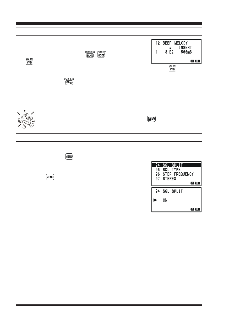
CTCSS/DCS/EPCS OPERATION
CTCSS/DCS/EPCS BELL OPERATION
12. When you wish to add a beep tone into the beep melody
strings, move the cursor to the place where you wish to enter the beep tone using the / key, then press the
key repeatedly until the “
eration Mode” slot turns into “
second to add the new beep tone (Tone: “C2”, Tone Length: “500mS”).
13. Press and hold the key for one second to delete all data after the current position
that may have previously been stored in the User Beep Melody.
14. When you have programmed User Beep Melody, press the PTT switch briefly to save
the new setting and exit to normal operation.
You may check your work by monitoring the programmed User Beep Melody.
To do this, repeat steps 1 - 4 above, then press the key.
The VX-8R can be operated in a Split Tone configuration via the Set mode.
1. Press and hold the key for one second to enter the Set Mode.
2. Rotate the DIAL knob to select Set Mode Item
SPLITSPLIT
SPLIT.
SPLITSPLIT
3. Press the key briefly to enable adjustment of this Set
Mode Item.
4. Rotate the DIAL knob to select “
Tone feature).
5. Press the PTT switch briefly to save the new setting and
exit to normal operation.
SELECTSELECT
SELECT” notation in the “Op-
SELECTSELECT
INSERTINSERT
INSERT”. Now, press and hold in the key for one
INSERTINSERT
SPLIT TONE OPERATION
94: SQL94: SQL
94: SQL
94: SQL94: SQL
ONON
ON” (to enable the Split
ONON
When the Split Tone feature is activated, you can see the following additional parameters
after the “
Select the desired operating mode from the selections shown above.
MESSAGEMESSAGE
MESSAGE” parameter while selecting the Set Mode Item
MESSAGEMESSAGE
D CDD CD
D CD: DCS Encode only (“
D CDD CD
TONE-DCSTONE-DCS
TONE-DCS: Encodes a CTCSS Tone and Decodes a DCS code
TONE-DCSTONE-DCS
T-DT-D
(the “
T-D” icon will appear during operation)
T-DT-D
D CD-TONE SQLD CD-TONE SQL
D CD-TONE SQL: Encodes a DCS code and Decodes a CTCSS Tone
D CD-TONE SQLD CD-TONE SQL
D-TD-T
(the “
D-T” icon will appear during operation)
D-TD-T
DCDC
DC” icon will appear while operating)
DCDC
95: SQL TYPE95: SQL TYPE
95: SQL TYPE:
95: SQL TYPE95: SQL TYPE
VX-8R OPERATING MANUAL44

CTCSS/DCS/EPCS OPERATION
TONE CALLING (1750 HZ
If the repeaters in your country require a 1750-Hz burst tone for access (typically in Europe), you can set the key to serve as a “Tone Call” switch instead. To change the
configuration of this switch, we again use the Menu to help us.
1. Press and hold the key for one second to enter the Set Mode.
2. Rotate the DIAL knob to select Set Mode Item
CALLCALL
CALL.
CALLCALL
3. Press the key briefly to enable adjustment of this Set
Mode Item.
4. Rotate the DIAL knob to select “
5. Press the PTT switch briefly to save the new setting and
exit to normal operation.
To access a repeater, press and hold in the key for the amount
of time specified by the repeater owner/operator. The transmitter will automatically be
activated, and a 1750-Hz audio tone will be superimposed on the carrier. Once access to
the repeater has been gained, you may release the key, and use the PTT switch for
activating the transmitter.
T-CALLT-CALL
T-CALL” on the display.
T-CALLT-CALL
61: MONI61: MONI
61: MONI/
61: MONI61: MONI
)
T-T-
T-
T-T-
VX-8R OPERATING MANUAL 45

MEMORY MODE
The VX-8R provides a wide variety of memory system resources. These include:
“Regular” Memory Channels, which include:
900 “Standard” memory channels, numbered “
99 “Frequency Skip Memories,” numbered “
11
1” through “
11
901901
901” through “
901901
11 “Home” channels, providing storage and quick recall of one prime frequency
on each operating band.
50 sets of band-edge memories, also known as “Programmable Memory Scan”
L01L01
channels, labeled “
U01U01
L01/
U01” through “
L01L01
U01U01
24 Memory Banks, labeled “
b 1b 1
b 1” through “
b 1b 1
L50L50
U50U50
L50/
U50.”
L50L50
U50U50
b24b24
b24.” Each Memory Bank can be
b24b24
assigned up to 100 channels from the “regular” memory channels.
Special Memory Channels, which include:
One “Emergency Automatic ID (EAI)” Channel.
10 “Weather Broadcast” Channels.
57 VHF Marine Channels.
89 popular Short-wave Broadcast Station Memory Channels.
900900
900.”
900900
999999
999.”
999999
Standard Memory Channels
(900 channels)
9
8
8
4
3
2
1
EAI Channel
(1 channel)
Weather Broadcast Channels
(10 channels)
9
X
4
3
2
X
1
X
X
W
W
W
W
X
W
Frequency Skip Memory Channels
0
0
9
0
1
X
W
(99 channels)
2
1
0
0
9
9
I
A
E
VHF Marine Channels
(57 channels)
4
3
0
0
9
9
9
8
9
9
9
9
HOME Channels
(11 channels)
d
d
n
d
n
a
n
a
B
a
B
B
W
C
S
C
B
B
M
M
F
A
Short-wave Broadcast Station
PMS Memory Channels
(50 Sets)
4
3
U
/
2
U
1
/
4
U
/
3
L
U
/
2
L
1
L
L
2
-
d
d
d
n
1
n
n
a
-
d
d
n
d
n
a
d
n
a
B
n
a
B
a
V
B
z
B
T
r
i
-
H
z
A
F
M
H
H
4
M
V
4
0
1
5
Memory Channels
(89 channels)
a
a
d
B
B
B
n
V
.
a
z
o
T
B
f
-
H
.
n
F
I
M
o
f
H
0
n
U
I
3
4
0
9
5
4
U
/
U
/
0
9
5
4
L
L
VX-8R OPERATING MANUAL46

MEMORY MODE
(
REGULAR MEMORY CHANNEL OPERATION
MEMORY STORAGE
1. Select the desired frequency, while operating in the VFO mode. Be sure to set up any
desired CTCSS or DCS tones, as well as any desired repeater offset. The power level
may also be set at this time, if you wish to store it.
2. Press and hold in the key for 1/2 second.
3. Within five seconds of releasing the key, you need to make a decision regarding
channel storage. The microprocessor will automatically select the next-available “free” channel (a memory register
on which no data has been stored). If you do not wish to
make a change and accept the “free” channel, proceed to
step 4. If you wish to select a different channel number into which to store the data,
rotate the DIAL knob to select the desired memory channel.
Advice: You may jump 100 memory channels, if you’re in a hurry (101 Æ 201 Æ 301 …),
by pressing the key (multiple times, if necessary). If you see the “ ” icon at the
upper left of the channel number, it means that the channel currently has no data
written on it (i.e. the channel is “free”: the occupied channel displays the “ ” icon).
4. Press the key once more to store the frequency into memory.
5. You still will be operating in the “VFO” mode, so you may now enter other frequencies, and store them into additional memory locations, by repeating the above process.
)
1) You may change the automatic memory channel selection feature to select
the “next-highest memory channel above the last-stored memory channel”
instead of the “next-available ‘free’ channel” via the Set Mode Item 56:
MEMORY WRITE; see page 151.
2) You may disable the memory write function which prevents a memory write operation
if you should accidentally perform a wrong key sequence via the Set Mode Item 54:
MEMORY PROTECT. See page 151 for details. When the memory write protect is activated, the “PROTECT” notation appears on the display while a memory write operation is being performed.
3) You may change the duration time of the secondary function (press and holding the
key) of the key via the Set Mode Item 36: FW KEY HOLD TIME; see page 148.
IMPORTANT NOTE
On rare occasions the memorized data may become corrupted by miss operation,
or static electricity. When repairs are made the memory data may be lost. Please
write down or record the memorized information so you will be able to restore it if
needed.
VX-8R OPERATING MANUAL 47

MEMORY MODE
(
REGULAR MEMORY CHANNEL OPERATION
MEMORY STORAGE
)
STORING INDEPENDENT TRANSMIT FREQUENCIES (“ODD SPLITS”
All memories can store an independent transmit frequency, for operation on repeaters
with non-standard shift. To do this:
1. Store the receive frequency using the method already described under MEMORY STOR-
AGE (it doesn’t matter if a repeater offset is active).
2. Tune to the desired transmit frequency, then press and hold in the key for 1/2
second.
3. Within five seconds of releasing the key, rotate the DIAL knob to select the same
memory channel number as used in step “1” above.
4. Press and hold in the PTT switch, then briefly press the key once more while
holding the PTT switch in (this does not key the transmitter).
Whenever you recall a memory, which contains independently-stored transmit and receive frequencies, the “ ” indication will appear in the display.
)
MEMORY RECALL
1. While operating in the VFO mode, press the key to
enter the Memory mode.
2. Rotate the DIAL knob to select the desired channel.
3. If you press the key briefly, then rotate the DIAL knob,
the memory channel will be selected in 10 channels per step.
4. To return to the VFO mode, press the key.
1) When the radio is already set to the Memory mode, an easy way to recall
memories is to key in the memory channel number, then press the key.
For example, to recall memory channel #14, press Æ Æ .
2) You may change the step of the fast channel selection mode ( key + DIAL knob
via Set Mode Item 52: MEMORY FAST STEP. See page 150 for details.
VX-8R OPERATING MANUAL48
)

MEMORY MODE
(
REGULAR MEMORY CHANNEL OPERATION
HOME CHANNEL MEMORY
A special one-touch “HOME” channel is available for each operating band, to allow quick
recall of a favorite operating frequency on each band.
HOME CHANNEL RECALL
1. Press the key, then press the key to recall the Home
Channel on the band group where you are currently operating.
2. Press the key, then press the key again to return to
the previously-used frequency (either a VFO or a memory channel).
The transceiver switches to VFO mode if the DIAL knob is turned.
You may disable the above function (automatically switching to the VFO mode)
using Set Mode Item 38: HOME VFO.
HOME CHANNEL FREQUENCY CHANGE
The factory defaults for the Home channels are listed below. You may re-program the
Home channel in a manner identical to that used for the regular memories:
1. Select the desired frequency, while operating in the VFO mode. Be sure to set up any
desired CTCSS or DCS tones, as well as any desired repeater offset. The power level
may also be set at this time, if you wish to store it.
2. Press and hold in the key for 1/2 second.
3. While the memory channel number is blinking, just press the key. The frequency
and other data (if any) will now be stored in the special HOME channel register.
4. You may repeat this process on the other operating bands.
Note that the UHF
HOME channel is
the one used during
“Emergency” operation. See
page 107 for details regarding
this feature.
OPERATING BAND
[
BAND NUMBER
SW Band
50 MHz Ham Band[2
Air Band
144 MHz Ham Band[4
VHF-TV Band
Information Band 1[6
430 MHz Ham Band[7
UHF-TV Band
Information Band 2[9
AM Broadcast Band [A]
FM Broadcast Band [F]
DEFAULT HOME CHANNELS
]
[1]
]
[3]
]
[5]
]
]
[8]
]
USA VERSION
30.000 MHz
108.000 MHz
146.520 MHz
174.000 MHz
222.000 MHz
446.000 MHz
470.000 MHz
860.000 MHz
76.000 MHz
FREQUENCY
1.800 MHz
0.540 MHz
EXP VERSION
1.800 MHz
30.000 MHz
108.000 MHz
144.000 MHz
174.000 MHz
222.000 MHz
430.000 MHz
470.000 MHz
860.000 MHz
0.540 MHz
76.000 MHz
)
VX-8R OPERATING MANUAL 49

MEMORY MODE
(
REGULAR MEMORY CHANNEL OPERATION
)
LABELING MEMORIES
You may wish to append an alpha-numeric “Tag” (label) to a memory or memories, to aid
in recollection of the channel’s use (such as a club name, etc.). This is easily accomplished
using the Set Mode.
1. Recall the memory channel on which you wish to append a
label.
2. Press and hold the key for one second to enter the Set
Mode.
3. Rotate the DIAL knob to select Set Mode Item
NAMENAME
NAME.
NAMENAME
4. Press the key briefly to enable programming of the name
tag.
5. Rotate the DIAL knob, or press one of the keyboard keys,
to select the first digit of the desired label.
Example 1: Rotate the DIAL knob to select any of the 61
available characters.
Example 2: Press the key repeatedly to toggle among
the seven available characters associated with
that key: t Æ u Æ v Æ T Æ U Æ V Æ 8
6. Press the key to move to the next character.
7. Repeat steps 5 and 6 to program the remaining letters, numbers, or symbols of the desired label. A total of 16 characters may be used in the creation of a label.
8. If you make a mistake, press the key to backspace the
cursor, then re-enter the correct letter, number, or symbol.
9. When you have completed the creation of the label, press the PTT switch briefly to
save the label and exit to normal operation.
53: MEMORY53: MEMORY
53: MEMORY
53: MEMORY53: MEMORY
During Memory Recall (“MR”) with Mono Band operation, the
alphanumeric Tag will appear below the frequency display.
The alphanumeric Tag does not appear if you activate
the Dual Receive Operation.
VX-8R OPERATING MANUAL50

MEMORY MODE
(
REGULAR MEMORY CHANNEL OPERATION
MEMORY OFFSET TUNING
Once you have recalled a particular memory channel, you may easily tune off that channel, as though you were in the “VFO” mode.
1. With the VX-8R in the Memory Recall (“MR”) mode, select the desired memory
channel.
2. Now press the key, then press key. The “
dicator will be replaced by one which says “
Tuning”).
3. Rotate the DIAL, as desired, to tune to a new frequency.
The synthesizer steps selected for VFO operation on the current band will be the steps
used during Memory Tuning.
4. If you wish to return to the original memory frequency, press key briefly. The
TUNTUN
“
TUN” indicator will be replaced by “
TUNTUN
5. If you wish to store a new frequency set during Memory Tuning, just press and hold
in the key for one second, per normal memory storage procedure. The microprocessor will automatically set itself to the next-available clear memory location, and
you then press the key again, briefly to lock in the new frequency.
If you want to replace the original memory contents with the new frequency
settings, be sure to rotate the DIAL to the original memory channel number!
TUNTUN
TUN” (“Memory
TUNTUN
MRMR
MR.”
MRMR
MRMR
MR” in-
MRMR
)
Any required CTCSS/DCS changes, or repeater offset modifications, must be done before
storing the data into the new (or original) memory channel location.
VX-8R OPERATING MANUAL 51

MEMORY MODE
(
REGULAR MEMORY CHANNEL OPERATION
)
MASKING MEMORIES
There may be situations where you want to “Mask” memories so they are not visible
during memory selection or scanning. For example, several memories used only in a city
you visit infrequently may be stored, then “Masked” until you visit that city, at which time
you can “Unmask” them for normal use.
1. Press the key, if needed, to enter the Memory Recall (“MR”) mode.
2. Press and hold in the key for 1/2 second, then rotate
the DIAL to select the memory channel to be “Masked”
from view.
3. Press the key. The confirmation message (
will appear on the display. Press the key once more, the
display will revert to memory channel #1. If you rotate the
DIAL to the location you just “Masked,” you will observe
that it is now invisible.
4. To Unmask the hidden memory, repeat the above procedure: press and hold in the
key for 1/2 second, rotate the DIAL to select the masked memory’s number, then
press the key to restore the memory channel’s data.
Watch out! You can manually store data over a “Masked” memory, deleting
previous data, if you’re not careful. Use the “next available memory” storage technique to avoid over-writing a masked memory.
MR MASK?MR MASK?
MR MASK?)
MR MASK?MR MASK?
VX-8R OPERATING MANUAL52

MEMORY MODE
(
REGULAR MEMORY CHANNEL OPERATION
MEMORY BANK OPERATION
The large number of memories available in the VX-8R could be difficult to utilize without
some means of organizing them. Fortunately, the VX-8R includes provision for dividing
the memories into as many as 24 Memory Banks, so you can categorize the memories in a
manner convenient to you. You may enter and exit the “Memory Bank” mode by a single
press of the key, as we shall see below.
ASSIGNING MEMORIES TO A MEMORY BANK
1. Recall the memory channel to be assigned to a Memory
Bank.
2. Press and hold in the key for 1/2 second, then rotate the
DIAL knob to select the Memory Bank number where you
want to include this channel (Memory Bank numbers are
found before memory channel “
pear at the upper left of the Memory Bank number if some
channels have already been assigned to that Memory Bank
number. (If no channels are assigned to the Memory Bank, the “ ” icon appears on
the left of the Memory Bank number).
3. Press the key briefly.
4. At this point, the memory
channel data is copied into
the Memory Bank.
1) You may assign
one memory channel into several
Memory Banks.
2) The PMS memory channels
(L1/U1 through L50/U50) may not be assigned to a Memory Bank.
11
1”). The “ ” icon will ap-
11
Memory Channel
CH 1 145.000 MHz
CH 2 145.080 MHz
CH 3 435.000 MHz
CH 4 435.500 MHz
CH 5 145.800 MHz
CH 6 436.000 MHz
CH 7 128.800 MHz
CH 897 145.620 MHz
CH 898 436.780 MHz
CH 899 128.600 MHz
Memory Bank “1”
144 MHz Amateur Band Channels
Memory Bank “2”
430 MHz Amateur Band Channels
Memory Bank “3”
All Amateur Band Channels
Memory Bank “4”
Club Channels
Memory Bank “5”
Air Band Cha nnels
)
MEMORY BANK RECALL
1. Press the key, if needed, to enter the MR mode.
2. Press the key to activate the “Memory Bank” mode.
MRMR
The “
MR” indicator will be replaced by one of the Memory
MRMR
Bank numbers (“
B 1B 1
B 1” through “
B 1B 1
B24B24
B24”).
B24B24
3. Press the key, and then press the key,
then rotate the DIAL knob to select the desired
Memory Bank.
4. Press the key. Now, as you rotate the DIAL
knob to select memories, you will observe that you
can only select memory channels in the current Memory Bank.
VX-8R OPERATING MANUAL 53

MEMORY MODE
(
REGULAR MEMORY CHANNEL OPERATION
)
MEMORY BANK OPERATION
5. To change to another Memory Bank, press the key, then press the key. Now
rotate the DIAL knob to select the new Memory Bank, then press the key again.
6. To exit from Memory Bank operation, just press the key. The Memory Bank
number will be replaced by the “
Recall mode, without utilization of the Memory Banks. The memories stored in the
various Banks will remain in those banks. You do not need to store them again.
REMOVING MEMORIES FROM A MEMORY BANK
1. Recall the memory channel to be removed from a Memory Bank.
2. Press and hold the key for 1/2 second, then press the key to remove the
memory channel data from the Memory bank.
MRMR
MR”, and you are now in the “regular” Memory
MRMR
CHANGING A MEMORY BANK
You may change the default Memory Bank Names, which are shown on the display while
selecting the Memory Bank your desire.
1. Press and hold in the key for one second to enter the Set Mode.
2. Rotate the DIAL knob to select the Set Mode Item
NAMENAME
NAME.
NAMENAME
3. Press the key briefly to enable adjustment of this Set
Mode Item.
4. Rotate the DIAL knob to select the memory bank on which
you wish to change a label.
5. Press the key briefly to enable changing of the name
tag.
6. Rotate the DIAL knob, or press one of the keyboard keys,
to select the first digit of the desired label.
Example 1: Rotate the DIAL knob to select any of the 61
available characters.
Example 2: Press the key repeatedly to toggle among
the seven available characters associated with
that key: a Æ b Æ c Æ A Æ B Æ C Æ 2
7. Press the key to move to the next character.
8. Repeat steps 6 and 7 to program the remaining letters, numbers, or symbols of the desired label. A total of 16 characters may be used in the creation of a label.
9. If you make a mistake, press the key to backspace the
cursor, then re-enter the correct letter, number, or symbol.
10. When you have completed the changes of the label, press the PTT switch to save the
label and exit.
S NAME
’
8: BANK8: BANK
8: BANK
8: BANK8: BANK
VX-8R OPERATING MANUAL54

MEMORY MODE
(
REGULAR MEMORY CHANNEL OPERATION
MOVING MEMORY DATA TO THE VFO
Data stored on memory channels can easily be moved to VFO, if you like.
1. Press the key, if needed, to enter the Memory Recall (“MR”) mode.
2. Press and hold in the key for 1/2 second, then rotate
the DIAL knob to select the memory channel containing the
frequency data to be moved to VFO.
3. Press the key. The confirmation message (
WRITE?WRITE?
WRITE?) will appear on the display. Press the key once
WRITE?WRITE?
more, the data will now have been copied to VFO, although
the original memory contents will remain intact on the previously stored channel. Press the PTT switch to cancel the
Moving Memory Data procedure, if desired.
If a Split Frequency Memory channel was transferred, the Tx frequency will be
ignored (you will be set up for Simplex operation on the Receive frequency).
OVER-OVER-
OVER-
OVER-OVER-
MEMORY ONLY MODE
Once memory channel programming has been completed, you may place the radio in a
“Memory Only” mode, whereby VFO operation is impossible. This may be particularly
useful during public-service events where a number of operators may be using the radio
for the first time, and ultimate simplicity of channel selection is desired.
)
To place the radio into the Memory Only mode, turn the radio off. Now press and hold in
the key while turning the radio on.
To return to normal operation, repeat the above power-on procedure.
VX-8R OPERATING MANUAL 55

MEMORY MODE
(
SPECIAL MEMORY CHANNEL OPERATION
)
The VX-8R provides Special Memory Channels, which are made up of:
10 Weather Broadcast Channels.
281 VHF Marine Channels
89 popular Short-wave Broadcast Station Memory Channels.
1) The Special Memory Channels are only recalled on the “A-Band”
2) You may assign the Special Memory Channels to a Memory Bank. See page ?? re-
garding Memory Bank Operation for details.
WEATHER BROADCAST CHANNELS
The VHF Weather Broadcast Station Memory Channel Bank has been pre-programmed at
the factory, for quick selection of NOAA weather information stations.
1. Press the key briefly to set the “A-Band” to the “Operating” band.
2. Press the key, then press the key, to recall the Special Memory Menu.
3. Press the key, repeatedly if necessary to select the “
CHCH
CH” (thus recalling the Weather Broadcast Memory Bank).
CHCH
4. Rotate the DIAL knob to select the desired Weather Broadcast channel.
5. If you wish to scan this bank to search for louder stations,
just press the PTT switch. When the scanner pauses on a
station, press the PTT switch once to halt the scan, or press
it twice to restart the scan.
6. To exit to normal operation, press the key, or press key followed by the
key.
WXWX
WX
WXWX
In the event of extreme weather disturbances, such as storms and hurricanes, the NOAA (National Oceanic and Atmospheric Administration) sends
a weather alert accompanied by a 1050 Hz tone and subsequent weather
report on one of the NOAA weather channels. You may disable the Weather Alert tone
via Set Mode Item 111: WX ALERT, if desired. See page 160.
WX CHANNEL FREQUENCY LIST
CH
1
162.550 MHz
2
162.400 MHz
3
162.475 MHz
4
162.425 MHz
5
162.450 MHz
FREQUENCY
CH
6
162.500 MHz
7
162.525 MHz
8
161.650 MHz
9
161.775 MHz
10
163.275 MHz
FREQUENCY
VX-8R OPERATING MANUAL56

MEMORY MODE
(
SPECIAL MEMORY CHANNEL OPERATION
VHF MARINE MEMORY CHANNELS
The VHF Marine Channel Bank has been pre-programmed at the factory, for quick selection.
1. Press the key briefly to set the “A-Band” to the “Operating” band.
2. Press the key, then press the key, to recall the Special Memory Menu.
3. Press the key, repeatedly if necessary to select the
INTVHFINTVHF
“
INTVHF” (thus recalling the VHF Marine Channel Bank).
INTVHFINTVHF
4. Rotate the DIAL to select any of the 57 available VHF Marine Channels.
5. Press the key to monitor the duplex frequency while
recalling a semi-duplex channel (such as Channel “1”). Press
the key again to revert to simplex monitoring.
6. To exit to normal operation, press the key, or press key followed by the
key.
VHF MARINE CHANNEL FREQUENCY LIST
CH
No.
1
156.050 160.650
2
156.100 160.700
3
156.150 160.750
4
156.200 160.800
5
156.250 160.850
6
7
156.350 160.950
8
9
10
11
12
13
14
15
FREQUENCY
(MHz)
156.300
156.400
156.450
156.500
156.550
156.600
156.650
156.700
156.750
CH
No.
16
17
18
19
20
21
22
23
24
25
26
27
28
FREQUENCY
(MHz)
156.800
156.850
156.900 161.500
156.950 161.550
157.000 161.600
157.050 161.650
157.100 161.700
157.150 161.750
157.200 161.800
157.250 161.850
157.300 161.900
157.350 161.950
157.400 162.000
CH
No.
60
61
62
63
64
65
66
67
68
69
70
71
72
73
74
FREQUENCY
(MHz)
156.025 160.625
156.075 160.675
156.125 160.725
156.175 160.775
156.225 160.825
156.275 160.875
156.325 160.925
156.375
156.425
156.475
156.525
156.575
156.625
156.675
156.725
CH
No.
75
76
77
78
79
80
81
82
83
84
85
86
87
88
FREQUENCY
(MHz)
156.775
156.825
156.875
156.925 161.525
156.975 161.575
157.025 161.625
157.075 161.675
157.125 161.725
157.175 161.775
157.225 161.825
157.275 161.875
157.325 161.925
157.375 161.975
157.425 162.025
)
VX-8R OPERATING MANUAL 57

MEMORY MODE
(
SPECIAL MEMORY CHANNEL OPERATION
)
SHORT-WAVE BROADCAST STATION MEMORY CHANNELS
The Short-wave Broadcast Station Memory Channel Bank has been pre-programmed at
the factory, for quick selection of Short-wave broadcast stations.
1. Press the key briefly to set the “A-Band” to the “Operating” band.
2. Press the key, then press the key, to recall the Special Memory Menu.
3. Press the key, repeatedly if necessary to select the
RADIORADIO
“
RADIO” (thus recalling the Short-wave Broadcast Station
RADIORADIO
Memory Channel Bank).
4. Rotate the DIAL to select any of the 89 available Shortwave Broadcast Stations.
5. When the radio is in Mono Band operation, the station “Tag”
will be displayed.
6. To exit to normal operation, press the key, or press
key followed by the key.
BROADCAST STATION FREQUENCY LIST
Ch
No.
10
11
12
13
14
15
16
17
18
19
20
21
22
23
24
25
26
27
28
29
30
31
32
33
34
35
36
37
38
39
40
41
42
43
44
Freq.
MODE
(MHz)
1
6.030
6.160
9.760
11.965
9.555
9.660
11.715
11.955
6.195
9.410
12.095
15.310
6.090
9.790
11.670
15.195
6.000
6.075
9.650
9.735
5.990
9.575
9.675
17.780
7.170
7.270
9.560
11.690
9.660
11.625
11.830
15.235
5.955
6.020
9.895
11.655
5.985
6.105
9.455
11.860
9.780
11.630
15.550
21.655
AM
AM
AM
AM
AM
AM
AM
AM
AM
AM
AM
AM
AM
AM
AM
AM
AM
AM
AM
AM
AM
AM
AM
AM
AM
AM
AM
AM
AM
AM
AM
AM
AM
AM
AM
AM
AM
AM
AM
AM
AM
AM
AM
AM
2
3
4
5
6
7
8
9
Tag
VOA
VOA
VOA
VOA
CANADA
CANADA
CANADA
CANADA
BBC
BBC
BBC
BBC
FRANCE
FRANCE
FRANCE
FRANCE
DEUTCHE WELLE
DEUTCHE WELLE
DEUTCHE WELLE
DEUTCHE WELLE
ITALY
ITALY
ITALY
ITALY
TURKEY
TURKEY
TURKEY
TURKEY
VATICAN
VATICAN
VATICAN
VATICAN
NEDERLAND
NEDERLAND
NEDERLAND
NEDERLAND
CZECH LIBERTY
CZECH LIBERTY
CZECH PRAGUE
CZECH LIBERTY
PORTUGAL
PORTUGAL
PORTUGAL
PORTUGAL
Station Name
Voice of America
Voice of America
Voice of America
Voice of America
Radio Canada International
Radio Canada International
Radio Canada International
Radio Canada International
British Broadcasting Corporation
British Broadcasting Corporation
British Broadcasting Corporation
British Broadcasting Corporation
Radio France International
Radio France International
Radio France International
Radio France International
Deutsche Welle
Deutsche Welle
Deutsche Welle
Deutsche Welle
Italian Radio International
Italian Radio International
Italian Radio International
Italian Radio International
Voice of Turkey
Voice of Trukey
Voice of Turkey
Voice of Turkey
Vatican Radio
Vatican Radio
Vatican Radio
Vatican Radio
Radio Nederland
Radio Nederland
Radio Nederland
Radio Nederland
Radio Liberty
Radio Liberty
Prague
Radio Liberty
Radio Portugal
Radio Portugal
Radio Portugal
Radio Portugal
Ch
No.
45
46
47
48
49
50
51
52
53
54
55
56
57
58
59
60
61
62
63
64
65
66
67
68
69
70
71
72
73
74
75
76
77
78
79
80
81
82
83
84
85
86
87
88
89
Freq.
(MHz)
9.650
11.880
11.910
15.290
6.055
7.315
9.590
9.925
9.985
6.065
9.490
15.240
17.505
6.120
9.560
11.755
15.400
5.920
5.940
7.200
12.030
7.465
11.585
15.615
17.535
6.045
9.595
11.620
15.020
7.190
7.405
9.785
11.685
6.135
7.275
9.570
13.670
6.165
7.200
9.750
11.860
5.995
9.580
9.660
12.080
MODE
AM
AM
AM
AM
AM
AM
AM
AM
AM
AM
AM
AM
AM
AM
AM
AM
AM
AM
AM
AM
AM
AM
AM
AM
AM
AM
AM
AM
AM
AM
AM
AM
AM
AM
AM
AM
AM
AM
AM
AM
AM
AM
AM
AM
AM
Tag
SPAIN
SPAIN
SPAIN
SPAIN
NIKKEI
NORWAY
NORWAY
NORWAY
NORWAY
SWEDEN
SWEDEN
SWEDEN
SWEDEN
FINLAND
FINLAND
FINLAND
FINLAND
RUSSIA
RUSSIA
RUSSIA
RUSSIA
ISRAEL
ISRAEL
ISRAEL
ISRAEL
INDIA
INDIA
INDIA
INDIA
CHINA
CHINA
CHINA
CHINA
KOREA
KOREA
KOREA
KOREA
JAPAN
JAPAN
JAPAN
JAPAN
AUSTRALIA
AUSTRALIA
AUSTRALIA
AUSTRALIA
Station Name
Radio Exterior de Espana
Radio Exterior de Espana
Radio Exterior de Espana
Radio Exterior de Espana
Radio Nikkei
Radio Norway International
Radio Norway International
Radio Norway International
Radio Norway International
Radio Sweden
Radio Sweden
Radio Sweden
Radio Sweden
Radio Finland
Radio Finland
Radio Finland
Radio Finland
Voice of Russia
Voice of Russia
Voice of Russia
Voice of Russia
Israel Broadcasting Authority
Israel Broadcasting Authority
Israel Broadcasting Authority
Israel Broadcasting Authority
All India Radio (AIR)
All India Radio (AIR)
All India Radio (AIR)
All India Radio (AIR)
China Radio International (CRI)
China Radio International (CRI)
China Radio International (CRI)
China Radio International (CRI)
Radio Korea
Radio Korea
Radio Korea
Radio Korea
Radio Japan
Radio Japan
Radio Japan
Radio Japan
Radio Australia
Radio Australia
Radio Australia
Radio Australia
VX-8R OPERATING MANUAL58

NOTE
VX-8R OPERATING MANUAL 59

SCANNING
GENERAL
The VX-8R allows you to scan just the memory channels, the entire operating band, or a
portion of that band. It will halt on signals encountered, so you can talk to the station(s) on
that frequency, if you like.
Scanning operation is basically the same in each of the above modes. Before you begin,
take a moment to select the way in which you would like the scanner to resume scanning
after it halts on a signal.
SETTING THE SCAN-RESUME TECHNIQUE
Three options for the Scan-Resume mode are available:
2.0sec - 10.0sec2.0sec - 10.0sec
2.0sec - 10.0sec: In this mode, the scanner will halt on a signal it encounters, and will
2.0sec - 10.0sec2.0sec - 10.0sec
hold there for the selected resume time. If you do not take action to
disable the scanner within that time period, the scanner will resume
even if the station is still active.
BUSYBUSY
BUSY: In this mode, the scanner will halt on a signal it encounters. When the
BUSYBUSY
carrier has dropped because the other station ceased transmission, the
scanner will resume. In the case of constant-carrier signals like Weather
Station broadcasts, the scanner will likely remain on this frequency
indefinitely. The Scan Re-start Delay time (default interval: 2 seconds)
is set by Set Mode Item
HOLDHOLD
HOLD: In this mode, the scanner will halt on a signal it encounters. It will not
HOLDHOLD
restart automatically; you must manually re-initiate scanning if you
wish to resume.
82: SCAN RE-START82: SCAN RE-START
82: SCAN RE-START.
82: SCAN RE-START82: SCAN RE-START
To set the Scan-Resume mode:
1. Press and hold the key for one second to enter the Set Mode.
2. Rotate the DIAL knob to select Set Mode Item
RESUMERESUME
RESUME.
RESUMERESUME
3. Press the key briefly to enable adjustment of this Set
Mode Item.
4. Rotate the DIAL knob to select the desired scan-resume
mode.
5. Press the PTT switch to save the new setting and exit to
normal operation.
The default condition for this Set Mode Item is “5.0sec”.
83: SCAN83: SCAN
83: SCAN
83: SCAN83: SCAN
VX-8R OPERATING MANUAL60

GENERAL
To set the Scan-Restart Delay Time:
1. Press and hold the key for one second to enter the Set Mode.
2. Rotate the DIAL knob to select Set Mode Item
RE-STARTRE-START
RE-START.
RE-STARTRE-START
3. Press the key briefly to enable adjustment of this Set
Mode Item.
4. Rotate the DIAL knob to select the desired Scan-Restart
Delay Time. Available selections are
(0.1sec/step) and
5. Press the PTT switch to save the new setting and exit to
normal operation.
The default condition for this Set Mode Item is “2.0sec”.
1.0sec1.0sec
1.0sec -
1.0sec1.0sec
10.0sec10.0sec
10.0sec (0.5sec/step).
10.0sec10.0sec
0.1sec0.1sec
0.1sec -
0.1sec0.1sec
82: SCAN82: SCAN
82: SCAN
82: SCAN82: SCAN
0.9sec0.9sec
0.9sec
0.9sec0.9sec
SCANNING
VX-8R OPERATING MANUAL 61

SCANNING
VFO SCANNING
This mode allows you to scan on the VFO mode.
1. Select the VFO mode by pressing the key, if necessary.
2. Press and hold in the key, then rotate the DIAL knob while holding in the
key (the current bandwidth for the VFO scanner will appear
on the display) to select the bandwidth for the VFO scanner. Available selections are
BANDBAND
BAND,
BANDBAND
±1 MHz±1 MHz
±1 MHz,
±1 MHz±1 MHz
BANDBAND
BAND: The scanner will sweep frequencies only on the cur-
BANDBAND
ALLALL
ALL: The scanner will sweep all frequencies between 1.8
ALLALL
PMS-XPMS-X
PMS-X: The scanner will sweep frequencies within the cur-
PMS-XPMS-X
3. Release the key to start scanning.
4. When the scanner encounters a signal strong enough to open the squelch, the scanner
will halt temporarily; the decimal point of the frequency display will blink during this
“Pause” condition.
5. The scanner will then resume according to the Scan-Resume mode selected in the
previous section.
6. To cancel scanning, press the PTT switch or key.
ALLALL
ALL, and
ALLALL
±2 MHz±2 MHz
±2 MHz,
±2 MHz±2 MHz
PMS-XPMS-X
PMS-X.
PMS-XPMS-X
±5 MHz±5 MHz
±5 MHz: The scanner will sweep frequencies within the selected
±5 MHz±5 MHz
±1 MHz±1 MHz
±1 MHz,
±1 MHz±1 MHz
bandwidth.
rent band.
MHz and 999.99 MHz (except the FM Broadcast Band:
76 - 107 MHz).
rently-selected PMS frequency pair. See page 68 for
details.
±2 MHz±2 MHz
±2 MHz,
±2 MHz±2 MHz
±5 MHz±5 MHz
±5 MHz,
±5 MHz±5 MHz
1) If you want to change direction of the scan while it is underway, rotate the
DIAL knob one click in the opposite direction. You’ll see the scanner turn
around and change frequency downward!
2) You may initiate upward or downward scanning in the previously selected band-
width, by pressing and holding either or key for one second, respectively.
3) You may change the scanner’s method of operation so the VFO frequency will jump
to the low band edge of the next band when the VFO frequency reaches the high edge
of the current band (or vice versa). See page 159 regarding Set Mode Item 105: VFO
MODE.
VX-8R OPERATING MANUAL62

SCANNING
VFO SCANNING
HOW TO SKIP (OMIT) A FREQUENCY DURING VFO SCAN
If the VFO scan stops on a frequency or frequencies that you do not need (such as a
spurious radiation from a television), such frequencies can be “skipped” during VFO scanning. A special “Frequency Skip Memory” bank is reserved to store these frequencies.
To skip a frequency during VFO scanning:
1. While VFO scanning is stopped on the frequency that you do not need, press and hold
the key for one second, then rotate the DIAL knob to select the desired Fre-
900900
quency Skip Memory channel (
select the next-available “free” Frequency Skip Memory channel (a memory register
on which no data has been stored). If you see the “ ” icon at the upper left of the
channel number, it means that the channel currently has no data written on it (i.e. the
channel is “free”).
2. Press the key to store the frequency into the Frequency Skip Memory. It will now
be ignored during VFO scanning.
To re-institute a frequency into the VFO scan loop:
1. Press the key, if needed, to enter the Memory Recall (“MR”) mode.
2. Press and hold in the key for one second, then rotate the DIAL knob to select the
memory channel to be re-instituted.
3. Press the key to delete the channel from the Frequency Skip Memory; this will
restore the frequency into the VFO scan loop.
999999
900 -
999). The microprocessor will automatically
900900
999999
The VX-8R has 100 VFO Frequency Skip Memory Channels.
SETTING THE SQUELCH LEVEL DURING ACTIVE SCANNING OPERATION
The VX-8R allows adjustment of the Squelch level “on the fly” while you are
scanning.
1. While the scanner is engaged, press the key,
then press the key (the current squelch level
will appear below the frequency display).
2. Rotate the DIAL to select the desired Squelch
level.
3. Press the PTT switch briefly to save the new setting and exit to normal op-
eration. In this case, pressing the PTT switch this one time will not causing
scanning to stop.
VX-8R OPERATING MANUAL 63

SCANNING
MEMORY SCANNING
Memory scanning is also easy to initiate:
1. Set the radio to the Memory Recall (“MR”) mode by pressing the key, if necessary.
2. Press and hold in the key, then rotate the DIAL knob while holding in the
key (the current Memory Scan mode will appear on the frequency display) to select the desired Memory Scan mode.
Available selections are
BANDBAND
BAND, and
BANDBAND
ALL CHANNELALL CHANNEL
ALL CHANNEL: The scanner sweeps all Memory channels.
ALL CHANNELALL CHANNEL
TAG1TAG1
TAG1: The scanner sweeps only those Memory channels with the same first
TAG1TAG1
TAG2TAG2
TAG2: The scanner sweeps only those Memory channels with the same first
TAG2TAG2
BANDBAND
BAND: The scanner sweeps only those Memory channels which are memo-
BANDBAND
PMS-XPMS-X
PMS-X: The scanner will sweep frequencies within the currently-selected PMS
PMS-XPMS-X
3. Release the key to start scanning.
4. As with VFO scanning, the scanner will halt on any signal encountered that is strong
enough to open the squelch; it will then resume scanning according to the Scan-Resume mode set previously. When there are no memory channels corresponding to the
selected Memory Scan mode, the “
5. To cancel scanning, press the PTT switch or key.
PMS-XPMS-X
PMS-X.
PMS-XPMS-X
digit of the alpha/numeric tag as the first channel on which scanning
started.
and second digits of the alpha/numeric tag as the first channel on
which scanning started.
rized on the same operating band as the first channel on which scanning started.
frequency pair. See page 68 for details.
ALL CHANNELALL CHANNEL
ALL CHANNEL,
ALL CHANNELALL CHANNEL
MS ERRMS ERR
MS ERR” notation will appear on the display.
MS ERRMS ERR
TAG1TAG1
TAG1,
TAG1TAG1
TAG2TAG2
TAG2,
TAG2TAG2
You may initiate the scanning in the previously selected Memory Scan Mode
by pressing and holding either or key for one second.
VX-8R OPERATING MANUAL64

SCANNING
MEMORY SCANNING
HOW TO SKIP (OMIT) A CHANNEL DURING MEMORY SCAN
As mentioned previously, some continuous-carrier stations like a Weather Broadcast station will seriously impede scanner operation if you are using the “Carrier Drop” ScanResume mode, as the incoming signal will not pause long enough for the transceiver to
resume scanning. Such channels may be “Skipped” during scanning, if you like:
1. Recall the Memory Channel to be skipped during scanning.
2. Press and hold the key for one second to enter the Set
Mode.
3. Rotate the DIAL knob to select Set Mode Item
SKIPSKIP
SKIP.
SKIPSKIP
4. Press the key briefly to enable adjustment of this Set
Mode Item.
5. Rotate the DIAL knob to select “
Channel will now be ignored during scanning. The “
selection is used for “Preferential Memory Scan”, described
in the next column.
6. Press the PTT switch briefly to save the new setting and
exit to normal operation.
SKIPSKIP
SKIP”. The current Memory
SKIPSKIP
55: MEMORY55: MEMORY
55: MEMORY
55: MEMORY55: MEMORY
ONLYONLY
ONLY”
ONLYONLY
When you recall the “skipped” memory channel manually, a
small “W” icon will appear at the left of the frequency display,
indicating it is to be ignored during scanning.
To re-institute a channel into the scanning loop, select “OFF”
in step 5 above (the “Skipped” channel will, of course, still be accessible via manual
channel selection methods using the DIAL knob in the Memory Recall (“MR”) mode,
whether or not it is locked out of the scanning loop).
VX-8R OPERATING MANUAL 65

SCANNING
MEMORY SCANNING
PREFERENTIAL MEMORY SCAN
The VX-8R also allows you to set up a “Preferential Scan List” of channels which you can
“flag” within the memory system. These channels are designated by a blinking “W” icon
when you have selected them, one by one, for the Preferential Scan List. When you initiate memory scanning on a channel with the blinking “W” icon appended, only those
channels bearing the blinking “W” icon will be scanned. If you initiate scanning on a
channel which does not have the blinking “W” icon appended, you will scan all channels
including those with the blinking “W” icon appended.
Here is the procedure for setting up and using the Preferential Scan List:
1. Recall the Memory Channel which you wish to add to the
Preferential Scan List.
2. Press and hold the key for one second to enter the Set
Mode.
3. Rotate the DIAL knob to select Set Mode Item
SKIPSKIP
SKIP.
SKIPSKIP
4. Press the key briefly to enable adjustment of this Set
Mode Item.
5. Rotate the DIAL knob to select “
6. Press the PTT switch briefly to save the new setting and
exit to normal operation.
ONLYONLY
ONLY”.
ONLYONLY
55: MEMORY55: MEMORY
55: MEMORY
55: MEMORY55: MEMORY
To initiate Preferential Memory Scan:
1. Press the key briefly to enter the Memory Recall (“MR”) mode, if you are not
using memories already.
2. Rotate the DIAL knob to select any channel which has a
blinking “W” icon appended to the channel number.
3. Press and hold in the / key for one second to initiate
Preferential Memory Scanning. Only the channels which
have a blinking “W” icon appended to the channel number will be scanned.
VX-8R OPERATING MANUAL66

SCANNING
MEMORY SCANNING
MEMORY BANK SCAN
When the Memory Bank feature is engaged, the scanner sweeps only memory channels in
the current Memory Bank. However, if the Memory Bank Link Scan feature is enabled,
you may sweep the memory channels in several Memory Banks which you have selected.
To enable the Memory Bank Link Scan feature:
1. Set the radio to the Memory Recall (“MR”) mode by pressing the key, if necessary.
2. Press the key to activate the “Memory Bank” mode.
MRMR
The “
MR” indicator will be replaced by one of the Memory
MRMR
Bank numbers (“
3. Press the key followed by the key. The Memory
Bank number will begin to blink.
4. Rotate the DIAL knob to select the first Memory Bank
BANK 1BANK 1
(“
BANK 1” ~ “
BANK 1BANK 1
Bank Link Scan.
5. Press the key briefly. A “
pear for two seconds on the display, indicating this Memory
Bank will now be swept during Memory Bank Scan.
6. Repeat steps 4 and 5 above, to append the “
notation to any other Memory Banks you wish to sweep.
7. Press the key.
8. Now, press and hold in the key for one second to initiate the Memory Bank Link Scan.
9. To remove a Memory Bank from the Memory Bank Link Scan, repeat steps 1 - 5
above, to change the “
B 1B 1
B 1” through “
B 1B 1
BANK24BANK24
BANK24”) you wish to sweep using Memory
BANK24BANK24
B-LINK ONB-LINK ON
B-LINK ON” notation into “
B-LINK ONB-LINK ON
B24B24
B24”).
B24B24
B-LINK ONB-LINK ON
B-LINK ON” notation will ap-
B-LINK ONB-LINK ON
B-LINK ONB-LINK ON
B-LINK ON”
B-LINK ONB-LINK ON
B-LINK OFFB-LINK OFF
B-LINK OFF”.
B-LINK OFFB-LINK OFF
1) When the Memory Bank is enabled for Memory
Bank scan, the Memory Bank number (“B x”) indication turns into “bx” (capital “B” turns into small
“b”).
2) You may enable/disable the Memory Bank scan via Set Mode
Item 7: BANK LINK.
MEMORY BANK SCAN “ENABLED”
MEMORY BANK SCAN “DISABLED”
VX-8R OPERATING MANUAL 67

SCANNING
)
PROGRAMMABLE (BAND LIMIT
This feature allows you to set sub-band limits for either scanning or manual VFO operation. For example, you might wish to set up a limit (in North America) of 144.300 MHz to
148.000 MHz to prevent encroachment into the SSB/CW “Weak Signal” portion of the
band below 144.300 MHz. Here’s how to do this:
1. Set the radio to the VFO mode by pressing the key, if necessary.
2. Using the techniques learned earlier, store (per the above concept) 144.300 MHz into
Memory Channel #
3. Likewise, store 148.000 MHz into Memory Channel #
Upper sub-band limit).
4. Set the radio to the Memory Recall (“MR”) mode by pressing the key.
5. Press and hold in the key for one second and rotate the
DIAL knob while holding in the key to select the de-
sired PMS frequency pair (
6. The “
7. Press and hold in the / key for one second to start
8. 50 pairs of Band Limit memories, labeled
MRMR
MR” label will be replaced by “
MRMR
Channel number will be replaced by “
ning will now be limited within the just-programmed range.
scanning within the just-programmed range.
You therefore can set upper and lower operation limits on a number of bands, if you
like.
L1L1
L1 (the “L” designates the Lower sub-band limit).
L1L1
PMSxxPMSxx
PMSxx).
PMSxxPMSxx
PMSPMS
PMS” and the Memory
PMSPMS
PxxPxx
Pxx”. Tuning and scan-
PxxPxx
M
EMORY SCAN
L1L1
U1U1
L1/
U1 through
L1L1
U1U1
U1U1
U1 (the “U” designates the
U1U1
(
PMS
L50L50
U50U50
L50/
U50 are available.
L50L50
U50U50
)
VX-8R OPERATING MANUAL68

SCANNING
“PRIORITY CHANNEL” SCANNING (DUAL WATCH
The VX-8R’s scanning features include a two-channel scanning capability which allows
you to operate on a VFO or Memory channel, while periodically checking a user-defined
Memory Channel for activity. If a station is received on the Memory Channel which is
strong enough to open the Squelch, the scanner will pause on that station in accordance
with the Scan-Resume mode set via Menu Item
Here is the procedure for activating Priority Channel Dual Watch operation:
1. Press the key briefly to enter the Memory Recall (“MR”) mode, if you are not
using memories already.
2. Press and hold in the key for one second, then rotate the DIAL knob to select the
memory channel you wish to be the “Priority” channel.
3. Press the key. The “
MRMR
the “
MR” label, indicating it is the Priority channel.
MRMR
4. Now set the VX-8R for operation on another memory channel, or on a VFO frequency.
5. Press and hold in the key for one second. The display
will remain on the VFO or memory channel selected. However, every five seconds the VX-8R will check the Priority
Channel for activity. The “
MDWMDW
“
MDW” while operating on the Memory channel or the “
MDWMDW
VDWVDW
by “
VDW” while operating on the VFO mode.
VDWVDW
6. If a station appears on the Priority Channel, the radio will pause on that channel, as
described previously.
PP
P” icon will appear to the right of
PP
MRMR
MR” label will be replaced by
MRMR
83: SCAN RESUME83: SCAN RESUME
83: SCAN RESUME. See page 60.
83: SCAN RESUME83: SCAN RESUME
VFOVFO
VFO” label will be replaced
VFOVFO
)
The receiving time interval (ratio) between the current channel (or VFO frequency) and
Priority channel may be customized via Set Mode Item
To set the receiving time interval:
1. Press and hold the key for one second to enter the Set Mode.
2. Rotate the DIAL knob to select Set Mode Item
3. Press the key briefly to enable adjustment of this Set
Mode Item.
4. Rotate the DIAL knob to select the desired time interval.
Available selections are
1.0sec1.0sec
1.0sec -
1.0sec1.0sec
5. Press the PTT switch briefly to save the new setting and
exit to normal operation.
The default condition for this Set Mode Item is “5.0sec”.
10.0sec10.0sec
10.0sec (0.5sec/step).
10.0sec10.0sec
0.1sec0.1sec
0.1sec -
0.1sec0.1sec
0.9sec0.9sec
0.9sec (0.1sec/step) and
0.9sec0.9sec
72: PRI TIME72: PRI TIME
72: PRI TIME.
72: PRI TIME72: PRI TIME
72: PRI TIME72: PRI TIME
72: PRI TIME.
72: PRI TIME72: PRI TIME
VX-8R OPERATING MANUAL 69

SCANNING
“PRIORITY CHANNEL” SCANNING (DUAL WATCH
)
PRIORITY REVERT MODE
During Priority channel operation (Dual Watch), a special feature is available which will
allow you to move to the Priority Channel instantly, without waiting for activity to appear
on the Priority Channel.
When this feature is enabled, and priority monitoring is engaged, just press the microphone’s
PTT switch. Operation will instantly revert to the Priority Channel.
To enable Priority Revert operation:
1. Press and hold the key for one second to enter the Set Mode.
2. Rotate the DIAL knob to select Set Mode Item
VERTVERT
VERT.
VERTVERT
3. Press the key briefly to enable adjustment of this Set
Mode Item.
4. Rotate the DIAL knob to select “
5. Press the PTT switch briefly to save the new setting and
exit to normal operation.
To disable Priority Revert operation, select “
ONON
ON”.
ONON
OFFOFF
OFF” in step 4 above.
OFFOFF
71: PRI RE-71: PRI RE-
71: PRI RE-
71: PRI RE-71: PRI RE-
VX-8R OPERATING MANUAL70

SCANNING
AUTOMATIC LAMP ILLUMINATION ON SCAN STOP
The VX-8R will automatically illuminate the LCD Lamp whenever the scanner stops on a
signal; this allows you to see the frequency of the incoming signal better at night. Note
that this will, of course, increase battery consumption, so be sure to switch it off during the
day (the default condition for this feature is “ON”).
The procedure for disabling the Scan Lamp is:
1. Press and hold the key for one second to enter the Set Mode.
2. Rotate the DIAL knob to select Set Mode Item
LAMPLAMP
LAMP.
LAMPLAMP
3. Press the key briefly to enable adjustment of this Set
Mode Item.
4. Rotate the DIAL knob to select “
5. Press the PTT switch briefly to save the new setting and
exit to normal operation.
OFFOFF
OFF”.
OFFOFF
BAND EDGE BEEPER
The VX-8R will automatically “beep” when a band edge is encountered during scanning
(either in standard VFO scanning or during PMS operation). You may enable this feature
(band edge beeper) when the frequency reaches the band edge while selecting the VFO
frequency by the DIAL knob.
81: SCAN81: SCAN
81: SCAN
81: SCAN81: SCAN
The procedure for enabling the Band-Edge Beeper is:
1. Press and hold the key for one second to enter the Set Mode.
2. Rotate the DIAL knob to select Set Mode Item
EDGEEDGE
EDGE.
EDGEEDGE
3. Press the key briefly to enable adjustment of this Set
Mode Item.
4. Rotate the DIAL knob to select “
5. Press the PTT switch briefly to save the new setting and
exit to normal operation.
ONON
ON”.
ONON
10: BEEP10: BEEP
10: BEEP
10: BEEP10: BEEP
VX-8R OPERATING MANUAL 71

Bluetooth® OPERATION
Installation of the optional BU-1 Bluetooth® Adapter Unit will enable, the VX-8R to
send/receive voice messages with the optional BH-1 or BH-2 Bluetooth® Headset via
wireless links.
PAIRING
When using the Bluetooth® Headset for the first time, the Bluetooth® Headset and the
VX-8R must be paired.
1. Make sure that the VX-8R and BH-1 (or BH-2) are both off.
2. Press and hold in the (PWR) switch for 2 seconds to turn the VX-8R on.
3. Press and hold the key for one second to enter the Set Mode.
4. Rotate the DIAL knob to select Set Mode Item
BLUETOOTH P-CODEBLUETOOTH P-CODE
BLUETOOTH P-CODE.
BLUETOOTH P-CODEBLUETOOTH P-CODE
5. Press the key briefly to enable selection of this Set Mode
Item.
6. The default PIN code (
You may change the PIN code, if desired, before continuing with step 7.
1) Press the key to enable changing of the PIN code.
2) Rotate the DIAL knob to set the first digit of the PIN code.
3) Press the key to save the first digit of the PIN code and move on to the next
place.
4) Repeat the previous steps to complete the PIN code. If you make a mistake, press
the key to move back to the incorrect number, then re-enter the correct
number.
7. Bring the BH-1 (or BH-2) close to the VX-8R, then press and hold in the POWER
switch of the BH-1 (or BH-2) until the LED indicator blinks red/blue alternately
(approximately five seconds).
8. Press the key to initiate the pairing.
9. If the pairing is successful (requires about 20 to 30 seconds), “ ” icon will appear on
the display of the VX-8R and the LED indicator of the BH-1 (or BH-2) will blink
blue.
10. Press the PTT switch of the VX-8R to save the new setting and return to normal
operation.
61116111
6111) will appear.
61116111
16:16:
16:
16:16:
VX-8R OPERATING MANUAL72

Bluetooth® OPERATION
ACTIVATION
1. Press and hold the key for one second to enter the Set Mode.
2. Rotate the DIAL knob to select Set Mode Item
BLUETOOTH SETBLUETOOTH SET
BLUETOOTH SET.
BLUETOOTH SETBLUETOOTH SET
3. Press the key briefly to enable selection of this Set Mode
Item.
4. Rotate the DIAL knob to select the TX/RX switching circuit of the Bluetooth® function:
VOX: OFFVOX: OFF
VOX: OFF: Disable the TX/RX switching circuit of
VOX: OFFVOX: OFF
the Bluetooth® function (RX only).
VOX: PTTVOX: PTT
VOX: PTT: Activates the Bluetooth® function for use with the PTT circuit.
VOX: PTTVOX: PTT
VOX: VOX HIGHVOX: VOX HIGH
VOX: VOX HIGH: Activates the Bluetooth® function with the VOX feature (VOX
VOX: VOX HIGHVOX: VOX HIGH
Gain: High).
VOX: VOX LOWVOX: VOX LOW
VOX: VOX LOW: Activates the Bluetooth® function with the VOX feature (VOX
VOX: VOX LOWVOX: VOX LOW
Gain: Low).
5. Press the key, then rotate the DIAL knob to select the
Battery Saver function:
SAVE: ONSAVE: ON
SAVE: ON: Activates the Battery Saver in the BH-1 (or
SAVE: ONSAVE: ON
BH-2).
If there has been no signal or key activity for 20 seconds, the Battery
Saver automatically puts the BH-1 (or BH-2) to “sleep”, to conserve
battery life. When a signal is received or the PTT switch is pressed, the
BH-1 (or BH-2) will wakeup and become active again.
Furthermore, if there has been no signal or key activity for 10 minutes,
the BH-1 (or BH-2) will turn off automatically.
SAVE: OFFSAVE: OFF
SAVE: OFF: Disable the Battery Saver in the BH-1 (or BH-2).
SAVE: OFFSAVE: OFF
6. Press the key, then rotate the DIAL knob to select the
receiver audio output mode of the Bluetooth® unit (this
parameter is ignored when using the BH-2 Bluetooth
Headset):
MODE: STEREOMODE: STEREO
MODE: STEREO: Outputs stereo receive audio while listening to the FM Broadcast
MODE: STEREOMODE: STEREO
band.
Note: When this mode is selected, the VOX function does not work
even if the VOX function is selected in step 4. above. The TX/RX
switching is performed by pressing the PTT switch.
MODE: MONOMODE: MONO
MODE: MONO: Outputs monaural receive audio while listening to the FM Broad-
MODE: MONOMODE: MONO
cast band.
7. If you wish to turn the Bluetooth® unit off to conserve transceiver battery power
when you are not operating the Bluetooth® function, perform the following procedures, otherwise, skip to next step.
17:17:
17:
17:17:
®
VX-8R OPERATING MANUAL 73
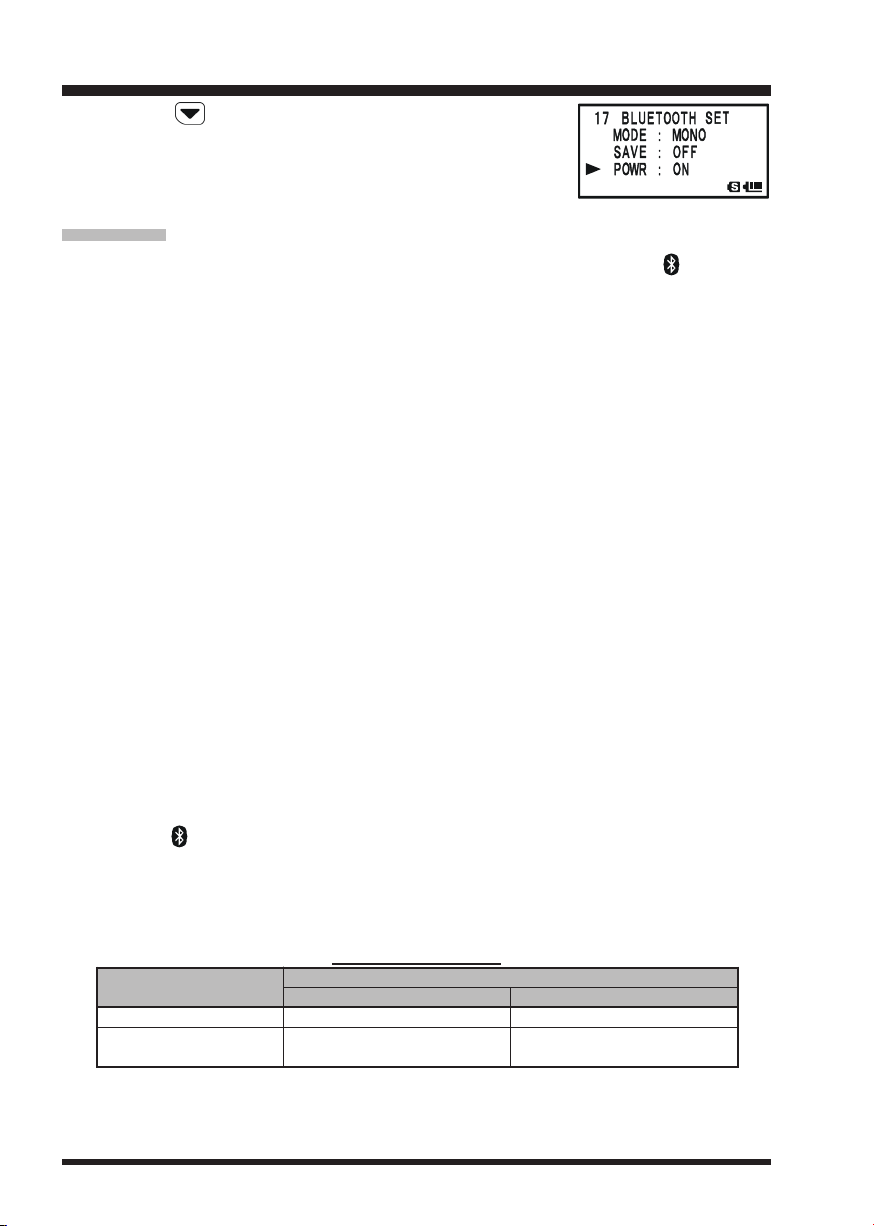
Bluetooth® OPERATION
Press the key, then rotate the DIAL knob to select the
POWRPOWR
“
POWR” parameter to “
POWRPOWR
8. Press the PTT switch of the VX-8R to save the new setting
and return to normal operation.
OPERATION
1. When the BH-1 (or BH-2) is correctly recognized by the VX-8R, “ ” icon will
appear on the display of the VX-8R and the LED indicator of the BH-1 (or BH-2
will blink blue.
2. Adjust the receiver audio level using the [VOLUME(+)]/[VOLUME
the BH-1 (or BH-2). Pressing the [VOLUME(+)] switch increases the receiver audio
level. Pressing the [VOLUME
3. Press the PTT switch on the BH-1 (or BH-2) to transmit. Release the PTT switch to
return to receive.
4. You may adjust the microphone gain (Five steps) of the BH-2 by pressing the [VOL-
UME(+)]/[VOLUME
sired.
Pressing the [VOLUME(+)] switch while pressing and holding the PTT switch increases the microphone level. Pressing the [VOLUME
holding the PTT switch decreases the microphone level. When the microphone gain
reaches maximum or minimum, a beep will be heard in the BH-2 speaker.
5. The communication range between the BH-1 (or BH-2) and VX-8R is around 1 m (3
ft). If you move out of range, a beep will be heard from the BH-1 (or BH-2) to alert
you. If you move back into range, the BH-1 (or BH-2) will beep to alert you that you
are back within range.
6. When the battery voltage of the BH-1 (or BH-2) is low;
a. the LED will blink Red and Blue.
b. a beep will be heard from the BH-1 (or BH-2).
c. the “ ” icon on the VX-8R will be blinking fast.
Charge the BH-1’s (or BH-2’s) battery with the optional CD-40 Charger Cradle.
OFFOFF
OFF”.
OFFOFF
(–)]
switches on
(–)]
switch decreases the receiver audio level.
(–)]
switch while pressing and holding the PTT switch, if de-
(–)]
switch while pressing and
)
When the BH-1 (or BH-2) is correctly recognized, the VX-8R’s internal speaker and
microphone are disabled.
BH-1/BH-2 BATTERY LIFE
OPERATING BAND
AM/FM Broadcast Band
Amateur Band
(
1:1:8 TX:RX:Standby
BATTERY LIFE (APPROX.
BH-1
3 hours
Battery Saver “ON”: 10 hours
)
Battery Saver “OFF”: 3 hours
Battery Saver “ON”: 20 hours
Battery Saver “OFF”: 3 hours
)
BH-2
6 hours
VX-8R OPERATING MANUAL74

NOTE
VX-8R OPERATING MANUAL 75

GPS OPERATION
The VX-8R allows the display of your position (Longitude/Latitude) when using the optional FGPS-2 GPS Antenna Unit.
1. Make sure that the transceiver is off.
2. Connect the optional FGPS-2 GPS Antenna Unit to the MIC/SP jack of the transceiver via the optional MH-74A7A Waterproof Speaker Microphone or CT-136 GPS
Antenna Adapter (see next page).
3. Press and hold in the (PWR) switch for 2 seconds to turn the transceiver on.
4. Press the key until the GPS screen appears.
5. When the transceiver succeeds in receiving a valid GPS
signal, your current position (Longitude/Latitude), current
time (UTC), and altitude will appear on the display. Rotate
the DIAL knob (or press the / key) to scroll through
additional lines of station text on the display.
The received satellite number appears at the lower right of
compasses (In the example at the right, it is 4 satellites).
When receiving a signal from more than 3 satellites, the “ ” icon will appear on the
display.
Advice: 1) When the FGPS-2 GPS Antenna Unit is first turned on, it may take several
minutes to compute a fix of your position. This is normal, as the GPS unit is downloading “almanac” information from the GPS satellites.
2) If the transceiver does not receive a valid GPS signal after three minutes have
passed, you may be in a poor location for satellite reception, such as inside of a house
or building; try moving to a less obstructed position.
6. If you walk a few meters from your current location, your
course direction is displayed on the compass of the display
and walking speed is displayed in the “
display.
7. To return to normal operation, press the key several times until the normal screen
appears.
SPDSPD
SPD” column of the
SPDSPD
1) When the FGPS-2 GPS Antenna Unit is activated, the current consumption increases approximately 40 mA. Therefore, battery life is reduced by
approximately 20 % when the FGPS-2 GPS Antenna Unit is activated.
2) You may memorize your current position as plotted by the GPS (up to ten points can
be saved) via the APRS/GPS Set Mode Item 21: MY POSITION. See page 165 for
details.
VX-8R OPERATING MANUAL76
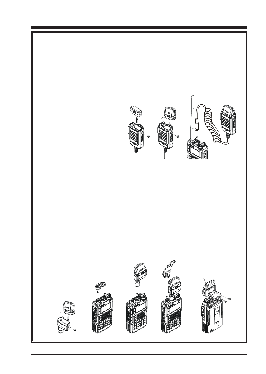
GPS OPERATION
FGPS-2 GPS Antenna Unit Installation
Using the MH-74A7A Waterproof Speaker/Microphone
1. Remove the small screw affixing the Dummy Cap, then remove the Dummy
Cap from the MH-74A7A.
2. Install the FGPS-2 to the MH-74A7A as shown in illustration, then affix the
FGPS-2 using the small screw that was removed from the dummy cap.
3. Turn the transceiver off, remove the Rubber Cap from
the MIC/SP jack of the transceiver
4. Connect the Microphone plug
to the MIC/SP jack of the
transceiver, and then screw the
ring of the Microphone plug
tightly.
5. The installation is now complete.
Using the CT-136 GPS Antenna Adapter
1. Install the FGPS-2 to the CT-136 as shown in the illustration, then affix the
FGPS-2 using the supplied screw.
2. Disconnect the antenna from the transceiver, and then remove the Rubber
Cap from the transceiver.
3. Turn the transceiver off, connect the CT-136 (with FGPS-2) to the MIC/SP
jack of the transceiver, and then screw the ring of the Microphone plug tightly.
4. Insert the Mounting Plate to the antenna jack.
5. Align the mounting guide to the transceiver’s depression, then affix the Mounting Plate to the CT-136 using the supplied two screws.
6. Connect the antenna to the antenna jack.
7. The installation is now complete.
Align the mounting guide
to the depression.
VX-8R OPERATING MANUAL 77

GPS OPERATION
You may customize the Time Zone (Time Offset), Display Unit of the GPS screen, and
GPS Datum for your own operating requirements via the APRS/GPS Set Mode.
SETTING THE TIME ZONE (TIME OFFSET
Sets the time offset between your local time and UTC (Universal Time Coordinated or
GMT: Greenwich Mean Time) shown on the display.
1. Press the key several times until the GPS screen appears on the display.
2. Press and hold the key for one second to enter the APRS/
GPS Set Mode.
3. Rotate the DIAL knob to select Set Mode Item
ZONEZONE
ZONE.
ZONEZONE
4. Press the key briefly to enable selection of this Set Mode
Item.
5. Rotate the DIAL knob to select the time offset from UTC.
See illustration below to find your offset time from UTC. If
UTC +0:00UTC +0:00
“
UTC +0:00” is assigned, the time is the same as UTC.
UTC +0:00UTC +0:00
6. Press the PTT switch briefly to save the new setting and
exit from the APRS/GPS Set Mode.
)
24: TIME24: TIME
24: TIME
24: TIME24: TIME
VX-8R OPERATING MANUAL78

GPS OPERATION
SELECTING THE DISPLAY UNITS OF THE GPS SCREEN
1. Press the key until the GPS screen appears.
2. Press and hold the key for one second to enter the APRS/
GPS Set Mode.
3. Rotate the DIAL knob to select Set Mode Item
UNITUNIT
UNIT.
UNITUNIT
4. Press the key briefly to enable adjustment of this Set
Mode Item.
5. Rotate the DIAL knob to select the preferred unit for “
tiontion
.MMM’.MMM’
tion” (
.MMM’ or
tiontion
.MMM’.MMM’
6. Press the key to change the cursor to “
rotate the DIAL knob to select the preferred unit (
mphmph
mph, or
mphmph
7. Press the key to change the cursor to “
select the preferred unit (
8. Press the PTT switch briefly to save the new setting and exit from the APRS/GPS Set
Mode.
KnotKnot
Knot).
KnotKnot
‘SS”‘SS”
‘SS”).
‘SS”‘SS”
mm
m or
mm
ftft
ft).
ftft
SELECTING THE MAP DATUM
While most operations (including APRS® operation) will utilize the default “WGS84”
database of locations, you may use a different database
18: GPS18: GPS
18: GPS
18: GPS18: GPS
Posi-Posi-
Posi-
Posi-Posi-
SpeedSpeed
Speed”, then
SpeedSpeed
KmKm
hh
Km/
h,
KmKm
hh
AltitudeAltitude
Altitude”, then rotate the DIAL knob to
AltitudeAltitude
1. Press the key until the GPS screen appears.
2. Press and hold the key for one second to enter the APRS/
GPS Set Mode.
3. Rotate the DIAL knob to select Set Mode Item
DATUMDATUM
DATUM.
DATUMDATUM
4. Press the key briefly to enable adjustment of this Set
Mode Item.
5. Rotate the DIAL knob to select the database you wish to
use. Available selections are
JapanJapan
Japan,
JapanJapan
6. Press the PTT switch briefly to save the new setting and
exit from the APRS/GPS Set Mode.
Tokyo KoreaTokyo Korea
Tokyo Korea, and
Tokyo KoreaTokyo Korea
WGS-84WGS-84
WGS-84,
WGS-84WGS-84
Tokyo OkinawaTokyo Okinawa
Tokyo Okinawa.
Tokyo OkinawaTokyo Okinawa
Tokyo MeanTokyo Mean
Tokyo Mean,
Tokyo MeanTokyo Mean
16: GPS16: GPS
16: GPS
16: GPS16: GPS
TokyoTokyo
Tokyo
TokyoTokyo
VX-8R OPERATING MANUAL 79

APRS® OPERATION
The VX-8R is equipped with a 1200/9600bps AX.25 Data Modem to enable APRS® (Automatic Packet Reporting System) operation. The Automatic Packet Reporting System
(APRS®) is a software program and registered trademark of Bob Bruninga, WB4APR.
PREPARATIONS
Before performing any APRS® operations, set your callsign, symbol, and position (Longitude/Latitude) into the VX-8R, and activate the AX.25 Data Modem via the APRS/GPS
Set Mode.
1. Press the key repeatedly until “STATION LIST” appears on the display.
2. Press and hold the key for one second to enter the APRS/
GPS Set Mode.
3. Rotate the DIAL knob to select Set Mode Item
CALLSIGNCALLSIGN
CALLSIGN.
CALLSIGNCALLSIGN
4. Press the key briefly to enable Callsign programming.
5. Rotate the DIAL knob or press the appropriate keys on your
keyboard to set the first letter or number in your callsign.
Example 1: Rotate the DIAL knob to select any of the 37
available characters.
Example 2: Press the key repeatedly to toggle among
the five available characters associated with that key: W Æ
X Æ Y Æ Z Æ 9 Æ W
6. When the correct character has been selected, press the
key to move on to the next character.
7. Repeat steps 5 and 6 as many times as necessary to complete your callsign.
8. If you make a mistake, press the key to backspace the
cursor and re-enter the correct letter/number.
The callsign can consist of up to six characters. If your
callsign is less than six characters, enter spaces into the remaining digits.
9. Press the key to move on to the next position, then
rotate the DIAL knob to select the SSID (Secondary Station
Identifier) if desired (see next page).
10. When you have completed entering your callsign and SSID,
press the key briefly to save the new setting.
11. Rotate the DIAL knob to select Set Mode Item
SYMBOLSYMBOL
SYMBOL.
SYMBOLSYMBOL
12. Press the key briefly to enable adjustment of this Set
Mode Item.
.....
.
20: MY20: MY
20: MY
20: MY20: MY
22: MY22: MY
22: MY
22: MY22: MY
VX-8R OPERATING MANUAL80

APRS® OPERATION
PREPARATIONS
13. Rotate the DIAL knob to select the desired icon.
14. Press the key briefly to save the new setting.
15. Rotate the DIAL knob to select Set Mode Item
TION COMMENTTION COMMENT
TION COMMENT.
TION COMMENTTION COMMENT
16. Press the key briefly to enable adjustment of
this Set Mode Item.
17. Rotate the DIAL knob to select the desired comment.
18. Press the key briefly to save the new setting.
19. Rotate the DIAL knob to select Set Mode Item
POSITIONPOSITION
POSITION.
POSITIONPOSITION
20. Press the key briefly to enable adjustment of
this Set Mode Item.
21. When the optional FGPS-2 GPS Antenna Unit is
connected to the transceiver, select “
AutoAuto
Auto” by rotat-
AutoAuto
ing the DIAL knob and advance to the next step, otherwise,
enter your position (Longitude/Latitude) manually.
1) Select “
LatLat
Lat” by rotating the DIAL knob.
LatLat
2) Press the key to enable entering of your
latitude using the Decimal system.
3) Use the and keys to navigation to each
column and then use the DIAL knob to select the desired numbers in each column. Repeat for each column
to complete your latitude entry.
23: POSI-23: POSI-
23: POSI-
23: POSI-23: POSI-
21: MY21: MY
21: MY
21: MY21: MY
SSID LIST
SSID
Non
Home Station, Home Station IGate
-1
Digipeater
-2
Digipeater
-3
Digipeater
-4
HF to VHF Gateway
-5
IGate (not Home Station)
-6
Operation via Satellite
-7
Hand-held Transceiver, such as VX-8R
-8
Maritime Mobile
-9
Mobile
-10
Operation via Internet
-11
APRS touch-tone User (and the Occasional Ballooes)
-12
Portable Units, such as Laptops, Camp Sites etc.
-13
Not Used
-14
Trackers
-15
HF Operation
DETAILS
VX-8R OPERATING MANUAL 81

APRS® OPERATION
PREPARATIONS
4) Move the cursor to “
key and then rotate the DIAL knob one click
clockwise to select “
using the same procedure as described above,
then advance to the next step.
22. Press the key briefly to save the new setting.
23. Rotate the DIAL knob to select Set Mode Item
APRS MODEMAPRS MODEM
APRS MODEM.
APRS MODEMAPRS MODEM
24. Press the key briefly to enable adjustment of
this Set Mode Item.
25. Rotate the DIAL knob to select “
AX.25 modem).
26. Press the PTT switch briefly to save the new setting and exit from the APRS/GPS Set
Mode.
You may memorize your current position as plotted by the GPS (up to ten points
can be saved). See page 165 for details.
The VX-8R provides many convenient functions for the APRS operation. Refer to the
“APRS/GPS Set Mode” chapter beginning with page 161 for details.
LatLat
Lat” using the /
LatLat
LonLon
Lon”. Enter your longitude
LonLon
1200bps1200bps
1200bps” (to activate the
1200bps1200bps
4:4:
4:
4:4:
VX-8R OPERATING MANUAL82

APRS® OPERATION
RECEIVING AN APRS BEACON
1. Set the “B-Band” to the APRS frequency. 144.390 MHz is generally used in North
America. If you don’t know the APRS frequency of your country, ask your dealer.
The AX.25 modem cannot be activated in the “A-Band”.
2. Disable the Receiver Battery Saver via the Set Mode Item
When the Receiver Battery Saver is turned on, the VX-8R can not reliably receive
an APRS Beacon.
3. Press the key several times until the “STATION LIST”
screen appears on the display. The “STATION LIST” screen
will save up to 40 stations. And the “STATION LIST” screen
sorts each station according to the received time.
4. To confirm the details of the received beacon, rotate the
DIAL knob (or press the / keys) to select the de-
sired station, then press the key. The “Received Data
and Time”, “Distance and Direction of the station”, and other
information will be displayed.
When the “Status Text” is included in the Mic Encoder Station Beacon, the “ ” icon appears at the upper right corner
of the display.
5. Rotate the DIAL knob (or press the / keys) to scroll
through additional lines or pages of the received information.
6. When the confirmation is finished, press the key to return to the STATION LIST
screen.
STATION LIST CHARACTER
CHARACTER
E
P
p
W
w
O
o
I
i
K
k
S
?
Mic-E: Mic Encoder Station
Position (Fixed/Moving) Station
Position (Fixed/Moving) Station (Compressed Data)
Weather Station
Weather Station (Compressed Data)
Object Station
Object Station (Compressed Data)
Item Station
Item Station (Compressed Data)
Killed Station
Killed Station (Compressed Data)
Status Station
Other Station (Include Non-Decoding Station)
DETAILS
79: SAVE RX79: SAVE RX
79: SAVE RX.
79: SAVE RX79: SAVE RX
STATION LIST CHARACTER
DIRECTION TO THE RECEIVED STATION
STATION LIST CHARACTER
STATUS TEXT “FLAG”
D
ISTANCE TO THE RECEIVED STATION
RECEIVED DATE & TIME
VX-8R OPERATING MANUAL 83

APRS® OPERATION
RECEIVING AN APRS BEACON
Deleting a Received Beacon from the “STATION LIST”
1. Press the key several times until the STATION LIST
screen appears on the display.
2. Rotate the DIAL knob (or press the / keys) to select
the beacon station to be deleted.
3. Press the key. The confirmation message (
will appear on the display. Press the key once more, the
selected beacon station will be deleted from the STATION
LIST.
APRS FILTER SETTING
The APRS filter option allows you to receive only specified types of the data.
1. Press the key several times until the STATION LIST
screen appears on the display.
2. Press and hold the key for one second to enter the APRS/
GPS Set Mode.
3. Rotate the DIAL knob to select Set Mode Item
FILTERFILTER
FILTER.
FILTERFILTER
4. Press the key briefly to enable adjustment of this Set
Mode Item.
5. Press the / key to select the “Filter” you wish to
exclude, then rotate the DIAL knob to select “
6. Repeat above steps and select “
wish to exclude.
7. When you have completed your selection, press the PTT switch to save the new
setting and exit to the STATION LIST screen.
OFFOFF
OFF” to any other filters you
OFFOFF
DELETE?DELETE?
DELETE?)
DELETE?DELETE?
3: APRS3: APRS
3: APRS
3: APRS3: APRS
OFFOFF
OFF”.
OFFOFF
VX-8R OPERATING MANUAL84

APRS® OPERATION
TRANSMIT AN APRS BEACON
To transmit your APRS Beacon, just press the key.
The VX-8R allows you to transmit your APRS Beacon automatically and repeatedly via
the APRS/GPS Set Mode.
1. Press the key several times until the STATION LIST
screen appears on the display.
2. Press and hold the key for one second to enter the APRS/
GPS Set Mode.
3. Rotate the DIAL knob to select Set Mode Item
BEACON TXBEACON TX
BEACON TX.
BEACON TXBEACON TX
4. Press the key briefly to enable adjustment of
this Set Mode Item.
5. Rotate the DIAL knob to select “
6. Press the key briefly, then rotate the DIAL knob
to select Set Mode Item
7. Press the key briefly to enable adjustment of
this Set Mode Item.
8. Rotate the DIAL knob to select the desired interval
time.
9. Press the PTT switch to save the new setting and exit to the
STATION LIST screen.
12: BEACON INTERVAL12: BEACON INTERVAL
12: BEACON INTERVAL.
12: BEACON INTERVAL12: BEACON INTERVAL
AUTOAUTO
AUTO”.
AUTOAUTO
14:14:
14:
14:14:
When the APRS frequency is busy (Squelch is opened), the VX-8R will not
transmit an APRS Beacon in manual or automatic modes. Insure that the
squelch is closed.
You may store five Status Text Messages (up to the 60 characters for each memory), and
you may transmit one of these Status Text Messages with the APRS Beacon.
1. Press the key several times until the STATION LIST
screen appears on the display.
2. Press and hold the key for one second to enter the APRS/
GPS Set Mode.
3. Rotate the DIAL knob to select Set Mode Item
CON STATS TXTCON STATS TXT
CON STATS TXT.
CON STATS TXTCON STATS TXT
4. Press the key briefly to enable adjustment of this Set
Mode Item.
5. Rotate the DIAL knob to select the Status Text register (
55
5) you wish to store data to.
55
6. Press the key briefly to begin comment entry into the
13: BEA-13: BEA-
13: BEA-
13: BEA-13: BEA-
11
1 -
11
VX-8R OPERATING MANUAL 85

APRS® OPERATION
TRANSMIT AN APRS BEACON
selected resister.
7. Rotate the DIAL knob (or press the keyboard) to select the
first character of the comment.
8. Press the key to move to the next character.
9. Repeat steps 6 and 7 to program the remainder of the comment.
10. If you make a mistake, press the key to back-space the cursor, then re-enter the
correct character.
11. You may add/delete a character to a comment using the following technique.
1) If you want to clear any previous comments, press the / key to select the
ALL CLEARALL CLEAR
“
ALL CLEAR” then press the key.
ALL CLEARALL CLEAR
2) If you want to delete a previously-stored comment after the cursor, press the /
key to select “
3) If you want to add a character, press the / key to select “
press the key.
12. When you have completed your entry, press the PTT switch to save the new setting
and exit to the STATION LIST screen.
DIGIPEATER PATH SETTING
The VX-8R allows you to set up to eight digipeaters for the APRS Packet Path.
CLEARCLEAR
CLEAR” then press the key.
CLEARCLEAR
INSERTINSERT
INSERT” then
INSERTINSERT
The VX-8R is preset to WIDE1-1 and WIDE2-1 digi-path to insure that your transmitted
APRS Beacon is received over wide area. We recommend that you use this setting by
default.
1. Press the key several times until the STATION LIST
screen appears on the display.
2. Press and hold the key for one second to enter the APRS/
GPS Set Mode.
3. Rotate the DIAL knob to select Set Mode Item
PATHPATH
PATH.
PATHPATH
4. Press the key briefly to enable adjustment of this Set
Mode Item.
5. Rotate the DIAL knob to select the Pass Number (
you wish to set
6. Press the key briefly to begin callsign entry into the
selected path.
7. Rotate the DIAL knob (or press the keyboard) to select the first character of the callsign
(with SSID) of the digipeater.
8. Press the key to move to the next character.
9. Repeats steps 7 and 8 to program the remainder of the callsign.
15: DIGI15: DIGI
15: DIGI
15: DIGI15: DIGI
11
88
1 -
8)
11
88
VX-8R OPERATING MANUAL86

APRS® OPERATION
TRANSMIT AN APRS BEACON
10. If you make a mistake, press the key to backspace the cursor, then re-enter the
correct character.
11. When you have completed your entry, press the PTT switch to save the new setting
and exit to the STATION LIST screen.
VX-8R OPERATING MANUAL 87

APRS® OPERATION
RECEIVING AN APRS MESSAGE
1. Set the “B-Band” to the APRS frequency. 144.390 MHz is generally used in North
America. If you don’t know the APRS frequency for your country, ask your dealer.
The AX.25 modem is not activated in the “A-Band”.
2. Disable the Receiver Battery Saver from Set Mode Item
When the Receiver Battery Saver is turned on, the VX-8R cannot reliably receive
APRS Messages.
3. Press the key several times until the APRS MESSAGE
screen appears on the display.
The APRS MESSAGE screen stores up to 20 stations. The
stations are sorted according to the time the station message is received.
4. To confirm the received message, rotate the DIAL knob (or
press the / keys) keys) to select the desired message, then press the key.
5. Rotate the DIAL knob (or press the / keys) to scroll through additional lines or
pages of the received stations message.
6. When you have finished reading your message, press the key to return to the
APRS MESSAGE screen.
Delete the Received Message from the “APRS MESSAGE” Screen
1. Press the key several times until the APRS MESSAGE
screen appears on the display.
2. Rotate the DIAL knob (or press the / keys) to select
the message to be deleted.
3. Press the key. The confirmation message (
will appear on the display. Press the key once more and
the selected message will be deleted from the APRS MESSAGE screen.
DELETE?DELETE?
DELETE?)
DELETE?DELETE?
79: SAVE RX79: SAVE RX
79: SAVE RX.
79: SAVE RX79: SAVE RX
VX-8R OPERATING MANUAL88

APRS® OPERATION
RECEIVING AN APRS MESSAGE
MESSAGE FILTER SETTING
The Message filter option allows you to choose to receive only specific types of message
information.
1. Press the key several times until the APRS MESSAGE
screen appears on the display.
2. Press and hold the key for one second to enter the APRS/
GPS Set Mode.
3. Rotate the DIAL knob to select Set Mode Item
FILTERFILTER
FILTER.
FILTERFILTER
4. Press the key briefly to enable adjustment of this Set
Mode Item.
5. Press the / key to select the “Filter” you wish to
utilize (
6. If you add a new message group code and/or bulletin group
code, select “
~ “
then press the key.
7. Use the
then use the DIAL knob to select the desired characters/
numbers in each column. Repeat for each column to complete the message (up to 9
characters) or bulletin (up to 5 characters).
8. When you have completed your selection, press the PTT switch to save the new
setting and exit to the APRS MESSAGE screen.
G1 ALLG1 ALL
G1 ALL or
G1 ALLG1 ALL
B3B3
B3” (for bulletin group code) by rotating the DIAL knob,
B3B3
G3G3
G3” ~ “
G3G3
and
G2 CQG2 CQ
G2 CQ).
G2 CQG2 CQ
G5G5
G5” (for message group code) or “
G5G5
keys to navigate to each column,
19: MSG19: MSG
19: MSG
19: MSG19: MSG
B1B1
B1”
B1B1
VX-8R OPERATING MANUAL 89

APRS® OPERATION
TRANSMIT AN APRS MESSAGE
1. Press the key several times until the APRS MESSAGE
screen appears on the display.
2. Press the key to show any previously-stored message
on the display.
3. Press the / key to select the “
the key to clear the previously-stored message.
4. Enter the callsign (with SSID) of the station you wish to
contact using the / key pad (select the cursor) or
turn the DIAL knob (select the number/letter).
5. When you have completed entering the callsign (and SSID),
press the key briefly.
6. Enter the message using the / key pad (select the
cursor) or turn the DIAL knob (select the number/letter).
Available length is up to 67 characters. You may add/delete
a message/character using the following procedure.
a. If you want to add a previously stored message (deter-
mined through APRS/GPS Set Mode item
MSG TXTMSG TXT
MSG TXT; see next page), press the / key to
MSG TXTMSG TXT
select the “
press the key.
b. If you want to delete the message after the cursor, press the / key to select
CLEARCLEAR
“
CLEAR” then press the key.
CLEARCLEAR
c. If you want to add a character, press the / key to select “
press the key.
7. When the message entry is complete, press the key to
transmit the message.
8. Press the key to return to the APRS MESSAGE screen.
The transmitted message is stored into the APRS MESSAGE
screen.
9. When an acknowledgment is received, the beeper will sound. If an acknowledgment
is not received, the APRS message is transmitted repeatedly five times, once each minute.
10. The remaining number of transmissions of the message is
shown on the display. When there is no acknowledgment
even if the APRS message transmits five times, the “¿”
icon (on the APRS MESSAGE screen) or “
tion (on the Detailed Message screen) will appear on the
display, instead of the remaining number of transmissions.
MSG TXT 1MSG TXT 1
MSG TXT 1” through “
MSG TXT 1MSG TXT 1
ALL CLEARALL CLEAR
ALL CLEAR”, then press
ALL CLEARALL CLEAR
6: APRS6: APRS
6: APRS
6: APRS6: APRS
MSG TXT 5MSG TXT 5
MSG TXT 5” then
MSG TXT 5MSG TXT 5
TXOUTTXOUT
TXOUT” nota-
TXOUTTXOUT
INSERTINSERT
INSERT” then
INSERTINSERT
VX-8R OPERATING MANUAL90

APRS® OPERATION
TRANSMIT AN APRS MESSAGE
STORE THE FIXED FORM MESSAGE
The VX-8R allows you to store five fixed form messages (up to 16 characters for each
message).
1. Press the key several times until the APRS MESSAGE
screen appears on the display.
2. Press and hold the key for one second to enter the APRS/
GPS Set Mode.
3. Rotate the DIAL knob to select Set Mode Item
MSG TXTMSG TXT
MSG TXT.
MSG TXTMSG TXT
4. Press the key briefly to enable adjustment of this Set
Mode Item.
5. Rotate the DIAL knob to select the Message register (
you wish to store your message to.
6. Press the key briefly to begin message entry into the
selected resister.
7. Rotate the DIAL knob (or press the keyboard) to select the
first character of the message.
8. Press the key to move to the next character.
9. Repeats steps 7 and 8 to program the remainder of the message.
10. If you make a mistake, press the key to backspace the
cursor and re-enter the correct character.
11. When you have completed your message entry, press the
PTT switch to save the new setting and exit to the APRS MESSAGE screen.
6: APRS6: APRS
6: APRS
6: APRS6: APRS
11
55
1 -
5)
11
55
VX-8R OPERATING MANUAL 91

ARTS
The ARTSTM feature uses DCS signaling to inform both parties when you and another
ARTSTM-equipped station are within communications range. This may be particularly
useful during Search-and Rescue situations, where it is important to stay in contact with
other members of your group.
Both stations must set up their DCS codes to the same code number, then activate their
ARTSTM feature using the command appropriate for their radio. Alert ringers may be
activated, if desired.
Whenever you push the PTT, or every 25 (or 15) seconds after
ARTSTM is activated, your radio will transmit a signal which
includes a (subaudible) DCS signal for about 1 second. If the
other radio is in range, the beeper will sound (if enabled) and
the display will show “
range display “
gins.
Whether you talk or not, the polling every 15 or 25 seconds will
continue until you de-activate ARTSTM. Every 10 minutes, moreover, you can have your
radio transmit your callsign via CW, to comply with identification requirements. When
ARTSTM is de-activated, DCS will also be deactivated (if you were not using it previously
in non-ARTSTM operation).
TM
(AUTOMATIC RANGE TRANSPONDER SYSTEM
IN RANGEIN RANGE
IN RANGE” as opposed to the out of
IN RANGEIN RANGE
OUT RANGEOUT RANGE
OUT RANGE” in which ARTSTM operation be-
OUT RANGEOUT RANGE
)
If you move out of range for more than one minute (four pollings), your radio will sense
that no signal has been received, three beeps will sound, and the display will revert to
OUT RANGEOUT RANGE
“
OUT RANGE.” If you move back into range, your radio will again beep, and the display
OUT RANGEOUT RANGE
will change back to the “
During ARTSTM operation, your operating frequency will continue to be displayed, but no
changes may be made to it or other settings; you must terminate ARTSTM in order to
resume normal operation. This is a safety feature designed to prevent accidental loss of
contact due to channel change, etc.
IN RANGEIN RANGE
IN RANGE” indication.
IN RANGEIN RANGE
VX-8R OPERATING MANUAL92

ARTS
TM
(AUTOMATIC RANGE TRANSPONDER SYSTEM
BASIC ARTSTM SETUP AND OPERATION
1. Set your radio and the other radio(s) to the same DCS code number, per the discussion
on page 36.
2. Press the key, then press the key. You will observe
OUT RANGEOUT RANGE
the “
OUT RANGE” display on the LCD below the operating
OUT RANGEOUT RANGE
frequency. ARTSTM operation has now commenced.
3. Every 25 seconds, your radio will transmit a “polling” call
to the other station. When that station responds with its own
ARTSTM polling signal, the display will change to “
RANGERANGE
RANGE” to confirm that the other station’s polling code was
RANGERANGE
received in response to yours.
4. Press the key to exit ARTSTM operation and resume normal functioning of the
transceiver.
ARTSTM won’t work if you have used the Lock feature to disable the PTT!
ININ
IN
ININ
ARTSTM POLLING TIME OPTIONS
The ARTSTM feature may be programmed to poll every 25 seconds (default value) or 15
seconds. The default value provides maximum battery conservation, because the polling
signal is sent out less frequently. To change the polling interval:
1. Press and hold the key for one second to enter the Set Mode.
2. Rotate the DIAL knob to select Set Mode Item
INTERVALINTERVAL
INTERVAL.
INTERVALINTERVAL
3. Press the key briefly to enable adjustment of this Set
Mode Item.
4. Rotate the DIAL knob to select the desired polling interval
25sec25sec
(
25sec or
25sec25sec
5. Press the PTT switch briefly to save the new setting and
exit to normal operation.
15sec15sec
15sec).
15sec15sec
6: ARTS6: ARTS
6: ARTS
6: ARTS6: ARTS
)
VX-8R OPERATING MANUAL 93

ARTS
TM
(AUTOMATIC RANGE TRANSPONDER SYSTEM
)
ARTSTM ALERT BEEP OPTIONS
The ARTSTM feature allows two kinds of alert beeps (with the additional option of turning
them off), to alert you to the current status of ARTSTM operation. Depending on your
location and the potential annoyance associated with frequent beeps, you may choose the
Beep mode which best suits your needs. The choices are:
IN RANGEIN RANGE
IN RANGE: The beeps are issued only when the radio first confirms that you are
IN RANGEIN RANGE
within range, but does not re-confirm with beeps thereafter.
ALWAYSALWAYS
ALWAYS: Every time a polling transmission is received from the other station, the
ALWAYSALWAYS
alert beeps will be heard.
OFFOFF
OFF: No alert beeps will be heard; you must look at the display to confirm
OFFOFF
current ARTSTM status.
To set the ARTSTM Beep mode, use the following procedure:
1. Press and hold the key for one second to enter the Set Mode.
2. Rotate the DIAL knob to select Set Mode Item
BEEPBEEP
BEEP.
BEEPBEEP
3. Press the key briefly to enable adjustment of this Set
Mode Item.
4. Rotate the DIAL knob to select the desired ARTS Beep mode
(see above).
5. Press the PTT switch briefly to save the new setting and
exit to normal operation.
5: ARTS5: ARTS
5: ARTS
5: ARTS5: ARTS
VX-8R OPERATING MANUAL94

ARTS
TM
(AUTOMATIC RANGE TRANSPONDER SYSTEM
CW IDENTIFIER SETUP
The ARTSTM feature includes a CW identifier, as discussed previously. Every ten minutes
during ARTSTM operation, the radio can be instructed to send “DE (your callsign) K” if
this feature is enabled. The callsign field may contain up to 16 characters.
Here is how to program the CW Identifier:
1. Press and hold the key for one second to enter the Set Mode.
2. Rotate the DIAL knob to select Set Mode Item
3. Press the key briefly to enable adjustment of this Set
Mode Item.
4. Rotate the DIAL knob to select “
ID function).
5. Press the key to enable programming your callsign.
Press and hold the key for two seconds to clear any
previous callsign, if desired.
6. Rotate the DIAL knob or press the keyboard to set the first
letter or number in your callsign.
Example 1: Rotate the DIAL knob to select any of the 37
available characters.
Example 2: Press the key repeatedly to toggle among
the four available characters associated with
that key: W Æ X Æ Y Æ Z Æ 9 Æ W
7. When the correct character has been selected, press the
key to move on to the next character.
8. Repeat steps 6 and 7 as many times as necessary to complete your callsign. Note that the “slant bar” (– • • – •) is
among the available characters, should you be a “portable”
station.
9. Press and hold the key for two seconds to delete all data after the cursor that may
have been previously stored.
10. If you make a mistake, press the key to backspace the cursor, then re-enter the
correct letter/number.
11. When you have entered your entire callsign, press the
key briefly to confirm the callsign, then press the PTT switch
to save the settings and exit to normal operation.
ONON
ON” (to activate the CW
ONON
21: CW ID21: CW ID
21: CW ID.
21: CW ID21: CW ID
.....
)
1) You may check your work by monitoring the entered callsign. To do this,
repeat steps 1 - 3 above, then press the key.
2) You may adjust the monitoring tone (CW sidetone pitch) via Set Mode
Item 28: CW PITCH. Available selections are 400 - 1000 Hz (50 Hz/step).
VX-8R OPERATING MANUAL 95

SPECTRUM ANALYZER OPERATION
The Spectrum Analyzer allows viewing operating activity on channels above or below the
current operating channel in the VFO mode.
The display indicates the relative signal strength on channels immediately adjacent to the
current operating frequency.
The Spectrum Analyzer feature can be activated only on the “A-Band” while the VX-8R
is in the “Mono” band operation.
Three basic operating modes for the Spectrum Analyzer are available:
1Time1Time
1Time: In this mode, the transceiver sweeps the current band once.
1Time1Time
CONTINUOUSCONTINUOUS
CONTINUOUS: In this mode, the transceiver sweeps the current band repeatedly until the
CONTINUOUSCONTINUOUS
key is pressed, or the Spectrum Analyzer is turned off.
Full TimeFull Time
Full Time: This mode is activated similar to a “
Full TimeFull Time
transceiver outputs the audio of the center frequency (T) from a speaker
when the Spectrum Analyzer is activated between 30 ~ 580 MHz (except
FM Broadcast Band).
SETTING UP THE SPECTRUM ANALYZER MODE:
1. Press and hold the key for one second to enter the Set Mode.
2. Rotate the DIAL knob to select Set Mode Item
ANALYZERANALYZER
ANALYZER.
ANALYZERANALYZER
3. Press the key briefly to enable adjustment of this Set
Mode Item.
4. Rotate the DIAL knob to select the desired Spectrum Analyzer mode (see above).
5. Press the PTT switch momentarily to save the new setting
and exit to normal operation.
CONTINUOUSCONTINUOUS
CONTINUOUS” mode. However, the
CONTINUOUSCONTINUOUS
91: SPEC-91: SPEC-
91: SPEC-
91: SPEC-91: SPEC-
TO ACTIVATE THE SPECTRUM ANALYZER:
1. Set the radio to the VFO mode on the “A-Band” in the “Mono” band mode.
2. Press the key, then press the key to activate the
Spectrum Analyzer.
3. When the Spectrum Analyzer is activated, press the or
key to change the visible bandwidth. Available selections are ±5, ±9, ±16, ±24, and ±50 channels (default: ±16 channels). The visible
bandwidth, however, depends on the selected channel step size, so match the default
channel steps with the amateur band you are using.
4. To turn the Spectrum Analyzer off and operate on the center (displayed) channel,
press the key to stop the sweep, if needed, then press the key followed by
key.
VX-8R OPERATING MANUAL96

NOTE
VX-8R OPERATING MANUAL 97

CHANNEL COUNTER OPERATION
The Channel Counter allows measuring of the frequency of a nearby transmitter, without
knowing that frequency in advance. The frequency can be measured by bringing the VX-
8R close to the transceiver which is transmitting.
The VX-8R performs a high-speed search within a ±5 MHz range from the frequency
displayed on the LCD. When the strongest signal in that range is identified, the VX-8R
displays the frequency of that (strongest) signal, and writes it into the special “Channel
Counter” memory.
Note: This Channel Counter is designed to provide an indication of the operating fre-
quency of the incoming signal, one that is close enough to allow the user to tune precisely
to the other station’s frequency. This feature is not, however, designed to provide a precise
determination of the other station’s frequency.
The Channel Counter feature can only be activated while the VX-8R is operating in the “A-Band”.
1. Set the “A-Band” to the VFO mode in the predicted frequency range for the transmitter to be measured, then set the “A-Band” to the “Operating” band (indicated in large
characters).
2. Bring the VX-8R into close proximity to the transmitter to be measured.
3. Rotate the DIAL knob, while pressing and holding in the
key, to select the “
4. Release the key to begin the Channel Counter; the frequency of the nearby station will be displayed. When the
channel counter is active, a 50 dB receiver front-end attenuator will be engaged. Therefore, only stations in close
proximity may have their frequencies measured using this
feature.
5. If it isn’t possible to determine the signal’s frequency, the
- - - NO - - -- - - NO - - -
“
- - - NO - - -” notation appears for two seconds, then the
- - - NO - - -- - - NO - - -
transceiver will return to the frequency on which you were
operating when you started Channel Counter operation.
6. When you are finished, press the key. The radio will exit from Channel Counter
operation.
CH COUNTERCH COUNTER
CH COUNTER” mode.
CH COUNTERCH COUNTER
VX-8R OPERATING MANUAL98
 Loading...