

Page 1
8/26/10
PEP2000
This procedure is used to update Main CPU Ver. 0152 and EDSP Ver. 11.54 the
flash programming for the FT-2000/D Transceivers.
We recommend installing the Flash Programming Software on a PC computer with Windows 2000,
XP or Vista Operating System; and use the CT-119 programming cable or 8-pin mini-DIN PGM-SW
(P0091526) and serial cable RS-232C, DB9F to DB9F straight cable.
NOTE: There are many USB adapters available; however some may not function with this software.
We recommend using the latest USB adapter driver software when available.
The update software is available from our website at http://www.yaesu.com. The CT-119
programming cable is available from your authorized Vertex Standard dealer. You may also order
by email to Vertex Standard parts department, yaesuparts@vxstdusa.com
If the CT-119 programming cable or is not available you will need a RS-232C, DB9F to DB9F
straight cable and 8pin mini-DIN PGM-SW (P0091526). If the DIN PGM-SW is not available you
will need to operate the internal program switch S3004. Please follow the instructio n s in
ADDENDUM: Page 7 and 9.
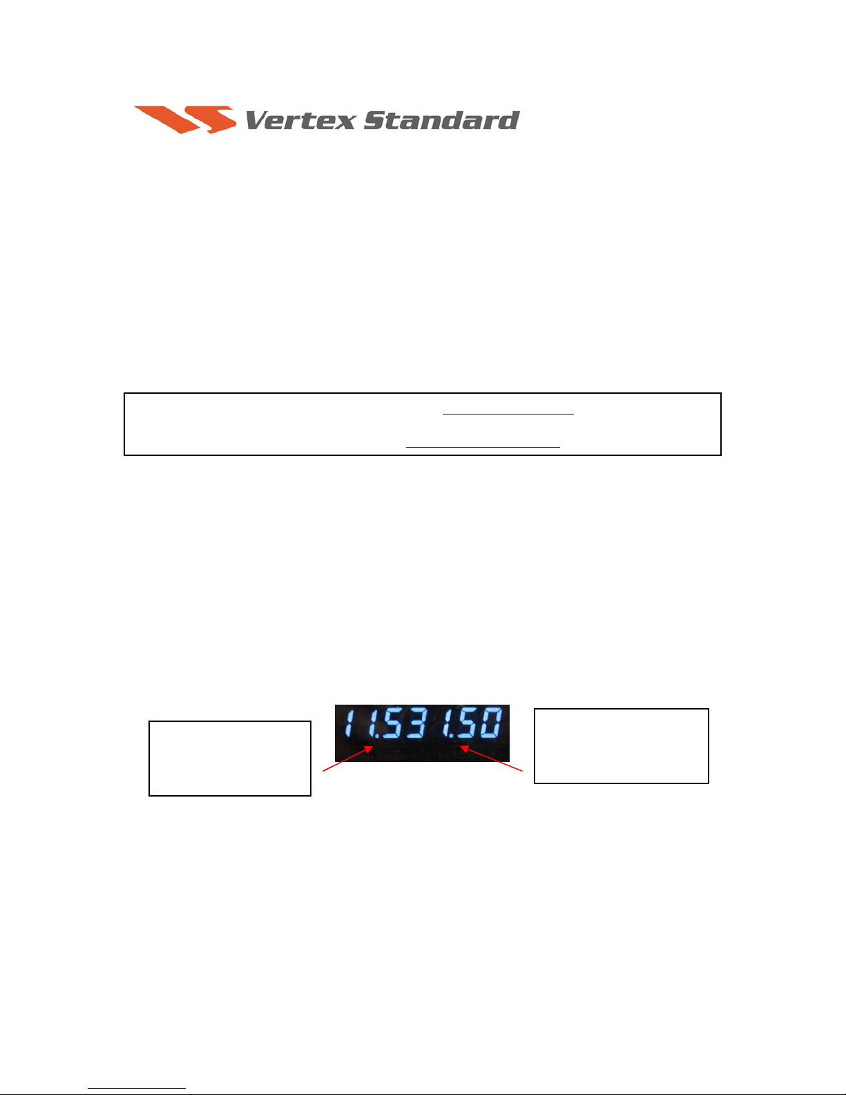
The software versions can be displayed on the radio
While holding the three buttons [GEN]+[50]+[ENT] turn the radio on. The software version will be
displayed in the VFO-A window for 5 seconds then the radio will start up in normal operation.
See below:
Example EDSP V11.53 and MAIN V0150 software version.
.
EDSP:
Software version 11.XX
(This image & version is for
illustration only)
*If you already have EDSP V11.54 and MAIN V0152 software versions, it is not necessary to update the FT2000/D again.
The software updates will work with all versions (AF, AS, EU, NA, OC, SA or all Countries) of the
FT-2000 and FT-2000D.
Main CPU:
Software version 01
(This image & version is for
illustration only)
XX
Page 2

The latest versions are listed below with the release dates.
・ MAIN Software Version 0152 (8/26/10)
・ EDSP Software Version 11.54 (4/23/10)
Ver. 0152 MAIN CPU implements improvements (also includes all previous updates):
• Stabilize initial power on display.
Ver. 11.54 EDSP implements improvements (also includes all previous updates):
• Corrected FM TX for a slight frequency offset.
NOTES:
*Rotate the [METER] switch to select “COM” (Compression). We recommend setting the PROC level within the 5dB
to 10dB range.
*When menu settings are saved on the DMU-2000 CF card and transferred to the new version, some previous versions
may not transfer correctly. Please check your menu, update the settings, and then save the new settings to the CF card.
Install the data file to PC
1. Down load the FT-2000 data file [FT-2000_PEP2000_8-26-10.zip] from the following website:
http://www.yaesu.com/indexVS.cfm?cmd=DisplayProducts&ProdCatID=102&encProdID=66EA
91711DFB68C03DED4AD35153E12C&DivisionID=65&isArchived=0
2. Save the FT-2000 data file [FT-2000_PEP2000_8-26-10.zip] to the desktop on your computer.
3. Unzip and Extract the contents of [FT-2000_PEP2000_8-26-10.zip] to the desktop of your
computer.
4. You will find the PEP2000_EDSP3 and PEP2000_MAIN folders on your desktop.
The programmers and software are now stored on your computer on the desktop. The files designated
in the last step above are ready to update your FT-2000/D Transceiver.
MAIN Software Update
This procedure is used for uploading new Software into the FT-2000/D Amateur Transceivers using
the CT-119 program cable. If you have the 8pin mini-DIN PGM-SW (P0091526) refer to the 8-pin
mini-DIN PGM-SW page 4.
*Don't forget to write down (or save to a CF Card) any personal menu settings you have changed from the
default before you start. Please see the DMU-2000 Data Management Operation Manual for the procedure
to save your settings to a CF card.
(1) Turn off the main power switch located on the back of the FT-2000 (or turn off the power
supply for FT-2000D and wait a minute, until the capacitors discharge) and remove the AC
power cord.
Page 3

(2) Connect the CT-119 Cable’s DB9F connector to the serial port COM1 in the back of your
computer. If you use a USB to serial adapter, you might need to change the COM Port number.
(3) Now go to the desktop open PEP2000_MAIN folder and find the FSW003 icon as shown
below. Double-click the FSW003 icon, displayed on the Program Screen.
NOTE: If you receive a “communications
error” message on your screen, click on the
Configure box and choose a different COM
port from the drop down menu. Then click the
WRITE button again.
(4) When the program opens, confirm that the file AH025_V0152.SFL is highlighted; if not, click
on it to highlight it.
(5) Remove the black cover from the PGM jack (bottom left on the rear panel). Plug the mini-DIN
connector of the CT-119 into the PGM jack. Be sure that the arrow indicator on the mini-DIN
plug is down
. Plug the AC cord into the radio and turn the main power switch on the back of the
radio to the ON position. [NOTE: The radio will not show a display now.]
Main Power SW
PGM
(6) Click on [WRITE] in the program window. A status bar with green bars should appear below
the [WRITE] button. Note disregard the on screen instruction to [3. Turn “S3004” on].
(7) When the loading process is complete, an [OK?] box will appear. Click [OK?].
(8) Turn off the main power switch, (or turn off the power supply for FT-2000D and wait a minute,
until the capacitors discharge) and unplug the AC power cord.
(9) Unplug the CT-119 from the radio.
(10) Plug the AC power cord into the radio and turn the main power switch on the back of the radio
to the ON position (or turn on the power supply for FT-2000D).
(11) Plug the radio back in. Press and hold in the [FAST] and [LOCK] keys; while holding them in,
press the front power switch to turn the radio on. This resets the radio and locks in the new
software.
(12) Turn the radio off. The main CPU updating process is now complete. Follow the instructions
below to update the EDSP.
Page 4

8-pin mini-DIN PGM-SW
1. Turn the main REAR power switch OFF.
2. Connect a RS-232C straight cable to the CAT connector.
3. Open the file FSW003.
4. Insert the 8-pin mini-DIN PMG-SW connector to FT-2000/D (PMG) jack.
5. Turn on the REAR Main power switch.
6. I choose the .sfl file of the version 0151 to write in and push WRITE of the screen.
7. When complete appears, click OK. Turn the REAR power switch OFF.
8. Remove the 8-pin mini-DIN PMG-SW and the RS-232C cable.
9. Turn on REAR power switch.
10. Reset the radio to default.
NOTE:
for a more detailed description see the Main CPU programming.
EDSP
EDSP Software Update
This procedure is used for uploading new EDSP Software into the FT-2000/D Amateur Transceivers,
from your personal computer, using the RS-232C, DB9F to DB9F straight cable.
1. Turn off the main power switch located on the back of the FT-2000 (or turn off the power supply
for FT-2000D and wait a minute, until the capacitors discharge) and remove the AC power cord.
2. Connect a serial RS-232C, DB9F to DB9F straight cable to the COM1 connector of your
computer and the 9-pin CAT connector on the rear of the transceiver. If you use a USB to serial
adapter, you might need to change the COM Port number.
Main Power SW
CAT
3. Reconnect the power cord and turn ON the main power switch located on the back of the FT-2000
(or turn ON the power supply for FT-2000D).
4. While holding the [DNR]+[CONT]+[DNF] buttons, press the front power switch to turn the
radio on. You will see [dSP Prg NO 1] on the radio display.
5. On your computer desk top open PEP2000_EDSP folder and find the EDSP V302 icon as shown
below. Double-click the EDSP V302 icon, displayed on the Program Screen.
Page 5

6. Click the Update button. You will see AH025H_V1154 out file displayed. If you do not see
AH025H_V1154 (as in the screen below), then open the “Look in:” window and go to the desktop
and find PEP2000_EDSP. Open the folder and AH025H_V1154 will be displayed in the
window. Click AH025H_V1154 out file to highlight it. Then click the Open button and wait until
the program is loaded, and 100% is indicated on the bar graph, [Completion!!!] will be displayed.
NOTE: If you receive a “Communications
Error” message on your screen you should
check the COM port number and speed under
Device Manager. The writing speed
38.4kbps is fixed in the download algorithm
of the EDSP board so you may need to set
the port speed close to 38.4kbps. Click on the
COM Select box arrow and choose a
different COM port from the drop down
menu in the EDSP-301 writer.
7. Turn the front Power Switch and the Main Power Switch in the back OFF (or turn off the power
supply for FT-2000D and wait a minute, until the capacitors discharge) and remove the AC power
cord. This resets the radio and locks in the new software. Remove the DB9F to DB9F cable. The
updating process is now complete.
It is important to reset the FT-2000/D. Plug the radio back in. Press and hold in the [FAST] and
[LOCK] keys; while holding them in, turn the radio back on (this resets the radio and locks in
the new software).
NOTE: We recommend trying the new factory default settings rather than transferring your old ones,
because of the changes in the EDSP and the Main CPU, you may wish to make new settings.
We hope this new software will increase your enjoyment of your FT-2000/D. Thank you for choosing
Yaesu radios. If you have any problems or questions please contact Vertex Standard, Amateur Tech
Support. amateurtech@vxstdusa.com
Best regards,
Mikio Maruya, WA6F
Executive Vice President
Engineering & Customer Service
Vertex Standard USA, Inc.
Vertex Standard USA, Inc. | 10900 Walker St. | Cypress, CA 90630 | 714.827-7600 | FAX: 714.827-8100
www.vertexstandard.com
Page 6

ADDENDUM
If the CT-119 programming cable or 8-pin mini-DIN PGM-SW (P0091526) is not
available you will need a serial cable RS-232C, DB9F to DB9F straight cable. Please
follow these instructions.
MAIN Software Update
*Don't forget to write down (or save to a CF Card) any personal menu settings you have changed from the
default before you start. Please see the DMU-2000 Data Management Operation Manual for the procedure
to save your settings to a CF card.
We recommend you follow this process, steps (1) thru (18), the first time you program your radio.
After you are familiar with the location of the switch S3004 you may wish to bypass Steps (2) and
(15), and operate the switch through the hole under the left rear foot (near the CAT connector). See
the illustration below Figure A. You must be extremely careful to avoid damage to the PC
components (which may not be covered by the Limited Warranty). Use a flashlight and insulated tool
to operate the switch.
(1) Turn off the main power switch located on the back of the FT-2000 (or turn off the power
supply for FT-2000D and wait a minute, until the capacitors discharge) and remove the AC
power cord.
(2) You must access the programming switch S3004. It is located on the control PC board on the
bottom of the FT-2000/D. To find and operate the switch, remove the top cover (9 black
screws). Remove the bottom cover (seven black screws). Remove the bottom shield (15 silver
screws). Carefully Place the Transceiver bottom side up on a sturdy cleared worktable. Find
the micro-switch on the pc board near the rear right hand corner when looking down at the
bottom of the FT-2000/D. (See the attached photo.)
(3) Connect a serial cable RS-232C, DB9F to DB9F straight cable to the COM1 connector of your
computer and the 9-pin CAT connector on the rear of the transceiver. If you use a USB to serial
adapter, you might need to change the COM Port number.
(4) Switch the programming micro switch S3004 to on.
(5) Connect the AC power cord. (In the case of the FT-2000D connect the power supply cables.)
(6) Turn on the main power switch. (Located on the rear panel of the FT-2000 or on the front of the
power supply for the FT-2000D.)
Page 7

(7) Now go to the desktop open PEP2000_MAIN folder and find the FSW003 icon as shown
below. Double-click the FSW003 icon, displayed on the Program Screen.
(8) When the program opens, confirm that the file AH025_V0152.SFL is highlighted; if not, click
on it to highlight it
(9) Click on [WRITE] in the program window. A green status bar should appear below the
[WRITE] button to show the progress of the download. Do not interrupt the process until it
completes.
(10) When the loading process is complete, an [OK?] box will appear. Click [OK?].
(11) Turn off the main power switch. (Located on the rear panel of the FT-2000 or on the front of the
power supply for the FT-2000D.)
(12) Disconnect the AC power cord (or turn off the power supply for FT-2000D and wait a minute,
until the capacitors discharge).
(13) Sw itch the program ming micro switch S3004 to the off position
(14) Remove DB9F straight cable from the CAT connector on the rear of the transceiver.
(15) Replace the bottom shield panel (15 screws). Replace the bottom case (7 black screws). Replace
the top case (9 black screws)
(16) Reconnect the power cord, (or power supply and connectors for FT-2000D)
(17) Turn the main power switch located on the back of the FT-2000 to the ON position (or turn on
the power supply for FT-2000D).
(18) Press and hold in the [FAST] and [LOCK] keys; while holding them in, press the front power
switch to turn the radio on. This resets the radio and locks in the new software. The updating
process is now complete. You may need to enter your custom menu settings now.
NOTE: If you receive a “communications
error” message on your screen, click on the
Configure box and choose a different COM
port from the drop down menu. Then click the
WRITE button again.
.
Page 8

Figure A
Remove the left
rear foot (near the
CAT connector)
expose the program
switch access hole.
to
Switch S3004 is visible through the hole.
Move the switch to the on (rear) position.
(Top of picture)
This is just a
screw hole for
reference
.
 Loading...