

Page 1

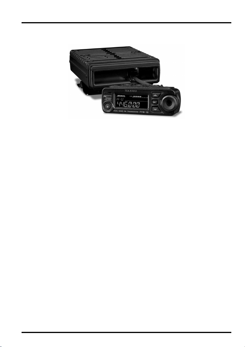
VHF/UHF DUAL BAND FM TRANSCEIVER
Downloaded by
RadioAmateur.EU
FTM-10R
OPERATING MANUAL
VERTEX STANDARD CO., LTD.
4-8-8 Nakameguro, Meguro-Ku, Tokyo 153-8644, Japan
VERTEX STANDARD
US Headquarters
10900 Walker Street, Cypress, CA 90630, U.S.A.
YAESU EUROPE B.V.
P.O. Box 75525, 1118 ZN Schiphol, The Netherlands
YAESU UK LTD.
Unit 12, Sun Valley Business Park, Winnall Close
Winchester, Hampshire, SO23 0LB, U.K.
VERTEX STANDARD HK LTD.
Unit 5, 20/F., Seaview Centre, 139-141 Hoi Bun Road,
Kwun Tong, Kowloon, Hong Kong
VERTEX STANDARD (AUSTRALIA) PTY., LTD.
Normanby Business Park, Unit 14/45 Normanby Road
Notting Hill 3168, Victoria, Australia
Page 2

Features ............................................................. 1
Front Panel & Top Panel ................................. 4
Rear Panel & LCD ........................................... 6
Accessories & Options ...................................... 8
Supplied Accessories ..................................... 8
Optional Accessories ...................................... 9
Installation ...................................................... 10
Preliminary Inspection ................................. 10
Installation Tips ............................................ 10
Safety Information ........................................ 11
Mobile Installation ....................................... 12
Base Station Installation ............................... 14
Antenna Considerations ............................... 15
Separate Installation ..................................... 16
Non-Separate Installation ............................. 21
Basic Operation .............................................. 22
Receive ......................................................... 22
Transmission ................................................ 23
Smart Menu Features ..................................... 24
AF Dual Function ......................................... 25
ARTSTM........................................................ 26
Dimmer function .......................................... 27
Horn Alert feature ........................................ 27
Intercom Function ........................................ 28
Monitor feature ............................................. 28
Public Address feature ................................. 29
Reverse feature ............................................. 29
Scan feature .................................................. 30
Smart SearchTM Operation ............................ 30
Squelch Level Adjust ................................... 31
TCALL ......................................................... 32
TX Power Select .......................................... 32
Intercom Volume Control ............................ 32
Memory Operation ......................................... 33
Memory Storage ........................................... 33
Memory Recall ............................................. 34
Memory Channel Customization .................. 35
Memory Group Bank ............................... 36
Memory Channel Number Change .......... 37
Memory Channel Sort .............................. 37
Labeling Memory ..................................... 38
Scan Type ................................................. 39
Skip/Preferential Scan Setting ................. 39
Squelch Level ........................................... 40
CTCSS frequency .................................... 40
DCS code ................................................. 41
CTCSS/DCS Operation ........................... 41
Storing Independent Transmit
Frequency (Odd Split) ....... 42
Transmitter Power Level .......................... 43
Deleting Memory ..................................... 43
Club Channel Operation ................................ 44
Recalling the Club Channel ......................... 44
Activating the Club Channel Monitor .......... 44
Message Feature ............................................. 46
Programming a Message .............................. 46
Programming a Member List ........................ 47
Cloning the Message .................................... 48
Set your Personal ID .................................... 49
Sending a Messages ..................................... 49
Contents
Cloning ......................................................... 50
Changing the Club Channel frequency ........ 52
Clock/Timer Operation .................................. 53
Set up the Clock ........................................... 53
Displays the Current Time ........................... 54
Using the Stop Watch Timer ........................ 55
Using the Interval Timer .............................. 55
Convenience Features .................................... 56
MUTE feature .............................................. 56
LOCK ........................................................... 56
Automatic Audio Volume Controller ........... 56
AF-VFO feature ........................................... 57
VOX Operation ............................................ 57
VOX Sensitivity ........................................... 58
Listening the AM/FM Broadcast Station ..... 58
Time-Out Timer (TOT) ................................ 58
Listening to external audio input .................. 59
Bluetooth® Operation ..................................... 60
AF Dual Function ........................................... 62
CTCSS Operation ........................................... 64
DCS Operation ............................................... 65
EPCS (Enhanced Paging &
Code Squelch) Operation ............ 66
Internet Connection Feature (WIRESTM) .... 68
DTMF Autodialer ........................................... 71
Repeater Operation ........................................ 73
Band Expansion .............................................. 74
Weather Broadcast Channel Operation ....... 75
Miscellaneous Setting ..................................... 76
Channel Step Selection ................................ 76
Changing the Operating Mode ..................... 76
PTT key function .......................................... 77
Key Beeper ................................................... 77
Smart Key Select .......................................... 77
Repeater Shift Direction ............................... 78
Repeater Shift Offset .................................... 78
Automatic Repeater Shift ............................. 78
Programming the Key Assignments ............. 79
Scanning Band ............................................. 80
Scan-Resume Mode ...................................... 80
Scan Direction .............................................. 81
Scan Start Direction ..................................... 81
Split Tone Operation .................................... 82
CTCSS/DCS/EPCS Bell Operation ............. 82
Battery Voltage Display ............................... 83
Temperature Display .................................... 83
Clock Format ................................................ 83
Time System ................................................. 84
Alarm Set ...................................................... 84
Interval Beep ................................................ 84
Automatic Power-Off (APO) ....................... 85
Audio Pitch Control ..................................... 85
Volume Setting Alert feature ....................... 86
Speaker Selection ......................................... 86
Stereo/Monaural Selection ........................... 87
MIC Gain Setting ......................................... 87
PTT Lock ..................................................... 87
Menu (“Set”) Mode ........................................ 88
Reset Procedure ............................................ 101
Troubleshooting ............................................ 102
Specifications ................................................ 103
Page 3
FEATURES
New Concept in Ultra compact Mobile transceivers
The ultra small size and design of this radio gives you many choices for mounting and
using this radio in your vehicle. The front panel may be separated from the main unit providing many placement and mounting options even for motor cycles or off road vehicles.
The microphone and the PTT switch are installed on the front panel so you can transmit
without connecting any microphone. You will not need an additional microphone or cable
to interfere with your driving on the road.
Simple set-up and no microphone or curl cord needed
The one touch, quick release front panel holder (new type) and the mounting bracket allow
you to place the front panel anywhere you want. The newly designed mobile mounting
bracket allows you to install or release the radio very easily.
The front panel has magnets and it is possible to install without using screws.
An angled panel adapter is included. The front panel may be adjusted up to 30 degrees
inclination to allow an improved, comfortable operating position.
Convenient Operation
The large function dial and key buttons afford simple operation, even while wearing driving gloves. The shape, size and position of the keys have been studied carefully. The design
will help avoid miss-operation of the keys while operating the vehicle.
Water proof front panel
The front panel is engineered to IP57 waterproof standards. You can mount the panel on the
handle bar of a motorcycle.
Superb visibility with new LCD panel
The bright LED and the Ocean Blue color LCD assure comfortable viewing night or day.
1FTM-10R OPERATING MANUAL
Page 4

FEATURES
Great new options to optimize your Motor Sports activities
-- Hands free operation with optional Bluetooth headset-When the optional Bluetooth® stereo headset is used with the optional Bluetooth® unit and
charger sleeve, you can enjoy comfortable hands free operation while you are driving.
Using the high audio output external speaker, the magnetic mounting brackets and the
Bluetooth® unit can provide hands-free operation and unlimited possibilities when using
this radio in any Motor Sports activity.
Reliable and advanced performance
The final transmitter amplifier produces up to 50 watts VHF and 40 watts UHF of reliable
and stable high power RF output.
The radio has wide receiving frequency capability, and an independent AM/FM broadcast
receiver. The Amateur radio receiver is specially designed for optimal Amateur band operation, with improved adjacent channel selectivity and IMD performance. You will appreciate the superior performance of the receiver when operating in strong electro magnetic
signal environments. The rugged chassis construction provides great reliability in any environment you may encounter on the car or the bike.
Loud Audio operation
A 2 inch diameter speaker. is mounted inside of the radio to provide powerful, low distortion AF output. The high volume will give excellent audio recognition, even in very noisy
environments.
Also available is a MEK-200-M10 optional external speaker. You can have loud audio
output with the 8 Watt AF amplifier built into the radio.
Sturdy rear chassis
A large aluminum die cast chassis forms a very sturdy rear case, and effectively radiates the
heat from the RF amplifier without the need of a cooling fan. The sandwich construction of
the chassis shields the electrical circuits from alternator and ignition noise. You have worry
free operation during long hours of rough handling in harsh environments.
Advanced features to support many Motor Sport activities.
U 500 memory channels with alpha-numeric labels.
U High output audio amplifier and optional external loudspeaker.
U The PA (Public Address) function permits communicating with a loud voice.
U The Intercom function provides communication through headphones between passen-
gers in the vehicle. Also the Bluetooth® unit can be used for the intercom.
U An AM /FM broadcast receiver is included. Audio line input is provided for connection
to your iPod® (FM broadcast and external input have stereo audio available)
U AF preset function alerts you when the AF audio level is changed by accident. You
enjoy the appropriate and optimized setting of volume level.
2 FTM-10R OPERATING MANUAL
Page 5

FEATURES
U The message send/receive function permits sending a programmable 16 character mes-
sage with the transmitter’s ID. You can send your words by “Message” function even
when the noise level at the opposite station is too high for audio communication.
U The wireless clone feature permits the settings and data of the radio to be duplicated in
other radios without connecting any wires. All the radios in your group traveling together can have the same settings with the easy setting operation.
U A convenient stopwatch function and display includes a Lap counter, Interval Timer/
Alert and Time.
U VOX is installed for hands free operation.
U Many new features include: Tone Control, One-touch band selection, Automatic audio
level control, Dimmer, TOT, WiRES, DC supply voltage indication, and APO.
3FTM-10R OPERATING MANUAL
Page 6
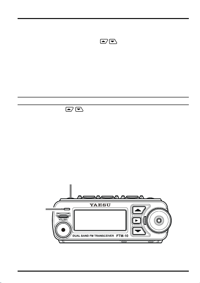
FRONT PANEL & TOP PANEL
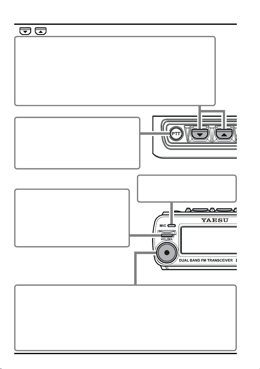
/ keys
These keys select the following operations.
• AF Dual Feature (See page 25) • Reverse (See page 29)
• ARTS Feature (See page 26) • Scan Operation (See page 30)
• Display Dimmer (See page 27) • Smart Search Operation (See page 30)
• Horn Alert Feature (See page 27) • Squelch Threshold Level (See page 31)
• Intercom Operation (See page 28) • TCALL (See page 30)
• Monitor Feature (See page 28) • TX Power Level (See page 32)
• Public Address (See page 29)
• Volume Level Control while Intercom Operation (See page 32)
PTT keys
Press this key to transmit.
Speak into the microphone while pressing this key.
P Release this key to return to receive.
P You may change this key function to “toggle”
mode (toggle the “transmit” and “receive” mode
each time the key is pressed). (See page 77)
MIC
TX/BUSY Indicator
This indicator glows green when a signal is
received.
This indicator glows red during transmission.
This indicator blinks blue when a message is
received.
This indicator glows white when transmitting
a message.
The internal microphone is located
here. Speak into the grill in a normal
voice level while pressing the PTT key.
VOL/SEL key
You may adjust the receiver audio level with the DIAL knob after pressing this key.
P The LED to the left of the DIAL knob will glow red when the DIAL knob is set to control
the receiver audio level.
P Press this key again or wait for three seconds, to cancel control of the audio level by the
Dial knob.
Mute Function:
Press and hold this key for one second to temporarily mute the receiver audio.
Press this key again to restore the receiver audio.
4 FTM-10R OPERATING MANUAL
Page 7
FRONT PANEL & TOP PANEL
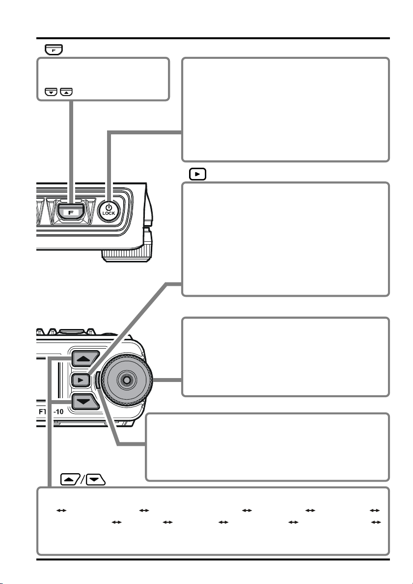
key
Press this key to activate the
function that is selected by the
/ keys.
POWER key
Press and hold this key for two seconds to toggle the
transceiver’s power on or off.
Lock Function:
Press this key momentarily while the transceiver is
turned on to toggle the key lockout feature on or off.
P You may also lock out the PTT key when the
LOCK mode is activated, by changing Menu Item
“F22 PTT LOCK”. See page 87.
key
P This key switches frequency control between the
VFO and Memory System.
P In the VFO mode, press and hold this key for one
second to enter the Memory Write mode and then
press this key again to store the frequency into
the memory.
P In the Memory mode, press and hold this key for
one second to enter the Memory Channel
Customization mode.
DIAL knob
P Selects the operating frequency and also selects
the memory channel.
P Adjusts the receiver audio level when the LED to
the left of the DIAL knob glows red.
P Select the Smart Menu Item and parameter when
the Smart Menu is activated.
LED
P This LED glows red when adjusting the receiver audio level
with the DIAL knob.
P This LED blinks orange when the Volume Setting Alert fea-
ture is active.
P This LED blinks yellow when the Timer feature is active.
keys
P Press these keys to switch the operating band as follows:
2 m Amateur Band 430 MHz Amateur Band FM BC Band AM BC Band
WX Band Audio Line Group Channel 2 m Amateur Band
P Press and hold this key for one second (MHz digits will blink), then rotate the DIAL
knob to change the frequency in 1 MHz steps.
5FTM-10R OPERATING MANUAL
Page 8
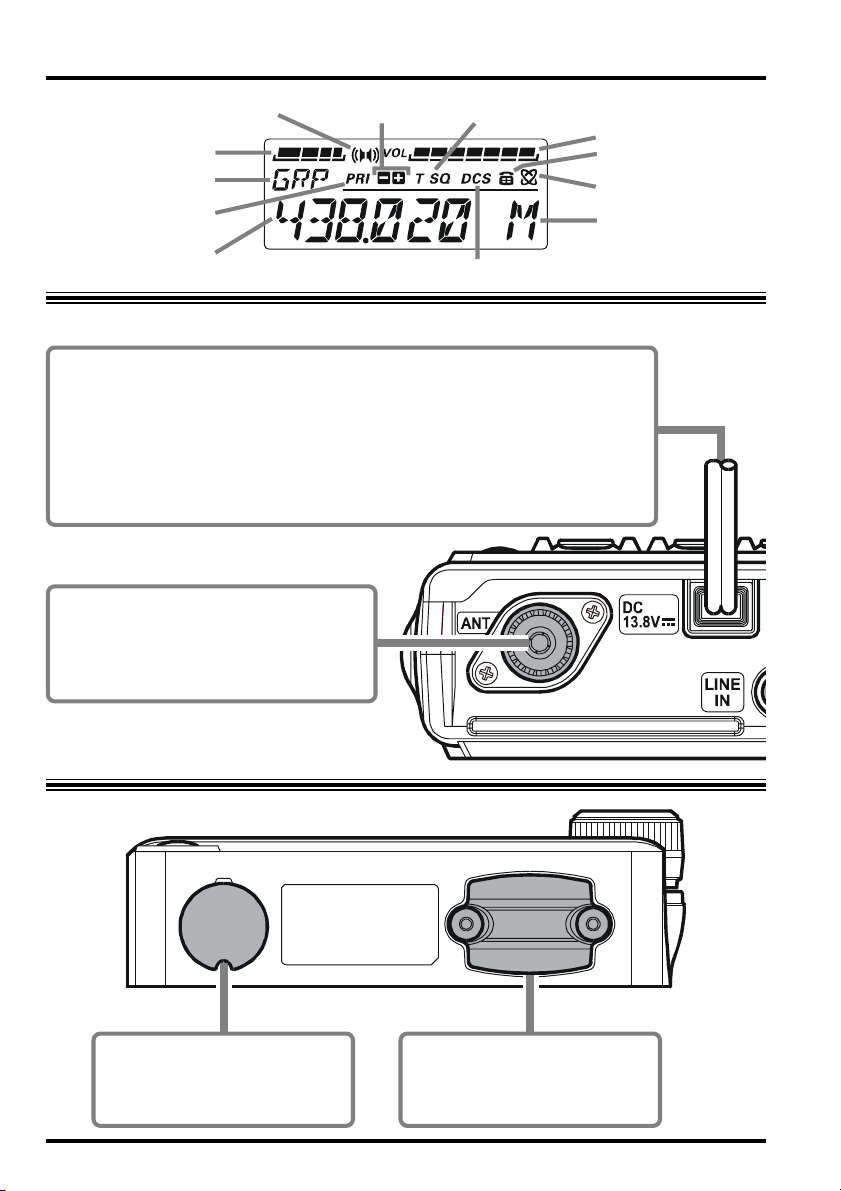
REAR PANEL & LCD
S- & PO Meter
Operating band
Club Channel Monitor
Feature Active
Operating Frequency
Stereo Audio
Digital Code Squelch (DCS) Operation
CTCSS OperationRepeater Shift Direction
Volume level
DTMF Feature Active
Internet Connection
Feature Active
Memory Mode Selected
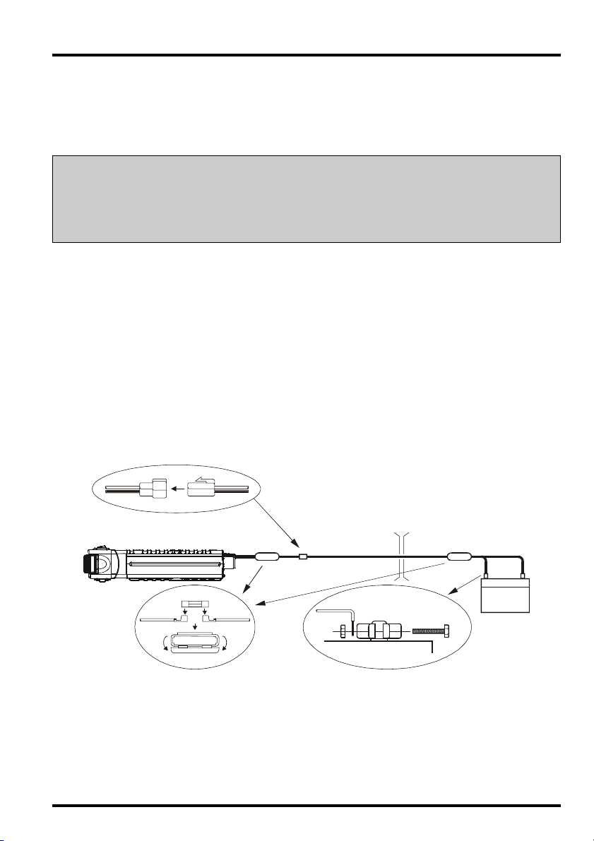
DC 13.8 V Cable Pigtail w/Fuse
Connect this pigtail to the car battery directly with the supplied DC cable.
P Connect the red lead to the positive side (+) of the battery and connect the
black lead to the negative side (-) of the battery. The DC cable is as short as
possible, because transmitting requires a high DC electrical current flow.
P Performance may be significantly reduced when connecting the DC cable
to the cigarette lighter plug or fuse box.
P Install a line filter if your vehicle has objectionable alternator noises.
ANT jack
Connect an efficient 144/430 MHz antenna, which is adjusted to 50-Ohm impedance. Use low-loss 50-Ohm coaxial
cable with type-M (PL259) connector.
You may connect an optional
®
CAB-1 Bluetooth
Head Set
Charger Sleeve here.
You may connect an optional
MEK-M10 Microphone Jack
here.
6 FTM-10R OPERATING MANUAL
Page 9
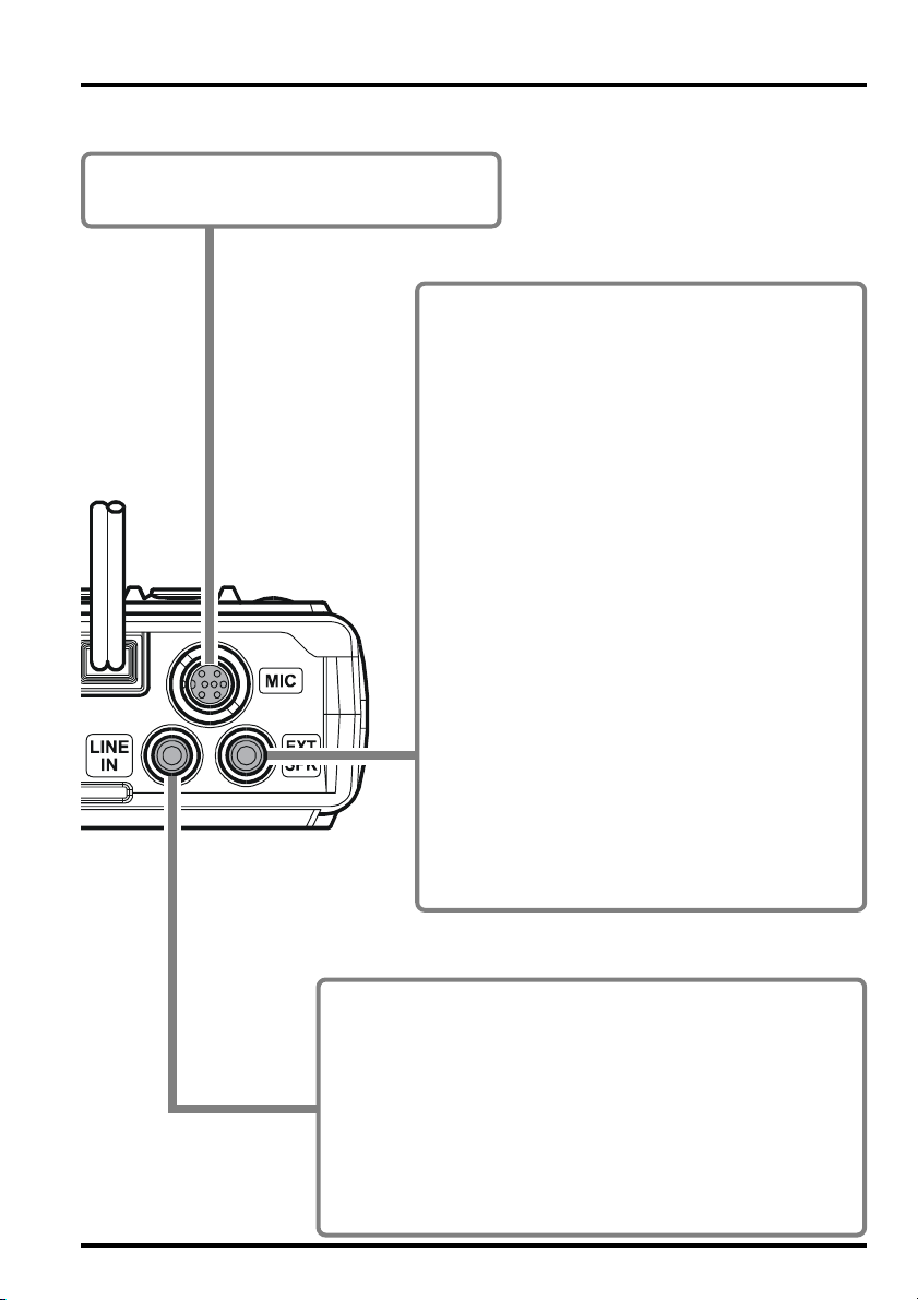
MIC jack
You may connect an optional MH-68A6J or MH-
B6J Hand Microphone to this jack if you use.
68
EXT SPK jack
This 3-contact 3.5-mm mini stereo-phone jack provides receiver audio output for an optional external speaker. The audio impedance is 4 Ohms, and
the level varies according to the setting of the front
panel VOL control.
P Inserting a plug into this jack disables audio from
the transceiver's internal speaker.
P When stereo speakers are connected to this jack,
and the Menu item “F42 STEREO” is set to “STE-
REO”, you may enjoy FM Broadcast audio, or
the external audio from the LINE IN jack in stereo.
P If there is no audio output from the external
speakers when connected to this jack, confirm
that the Menu item “F34 SPEAKER” is set to
“REAR” (See page 86).
P Use of a sound isolating headset while driving
on public roads is not lawful. An open type headset must be used for safety.
Hint: Menu Mode
The FTM-10R Smart Menu enables the configuration of 49 transceiver parameters to your favorite
settings.
REAR PANEL
LINE IN jack
Connect an external audio source (such as the iPod
jack using the after-market audio cable.
When using the audio line input to this jack, you may enable
the receiving of amateur signals while listening to your favorite music.
Adjust the input level with the volume control of the external
audio equipment connected.
The connection cable depends on the external audio equipment
you connect. Please ask your dealer.
®
) to this
7FTM-10R OPERATING MANUAL
Page 10
ACCESSORIES & OPTIONS
Downloaded by
RadioAmateur.EU
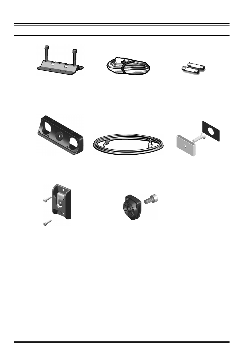
SUPPLIED ACCESSORIES
Mobile Mounting Bracket DC Power Cord W/Fuse Spare Fuse (15 A)
Angle Adapter
Front Panel Bracket
Speaker Cable
Hex Wrench (4 mm)
Hex Wrench (3 mm)
Operating Manual
Warranty Card
Separation Cable (3 m)
Front Panel Hanger
Magnet
8 FTM-10R OPERATING MANUAL
Page 11
ACCESSORIES & OPTIONS
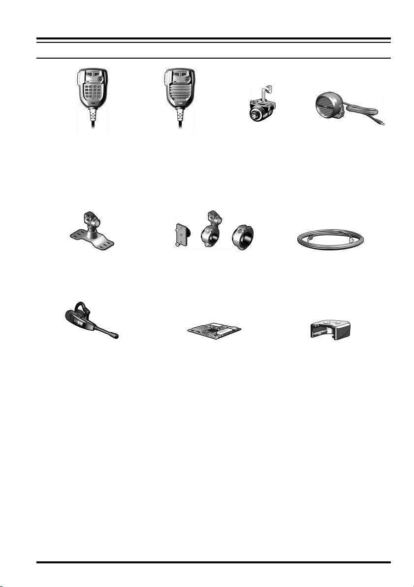
OPTIONAL ACCESSORIES
MH-68A6J
DTMF Microphone
MMB-M10
Multi-Angle Bracket
BH-1
Bluetooth® Head Set
FEP-4
Ear Phone for BH-1
MH-68B6J
Normal Microphone
MMB-M11
Handle Bar Bracket
BU-1
Bluetooth® Adapter Unit
MEK-M10
Microphone Jack
Separation Cable (6 m)
MLS-200-M10
High-Power External
Speaker
CT-M10
CAB-1
Bluetooth® Head Set
Charger Sleeve
Availability of accessories may vary in some regions. This product is designed to perform
optimally when used with genuine Vertex Standard accessories. Vertex Standard shall not
be liable for any damage or accidents such as fire, leakage or explosion of batteries, etc.,
caused by the malfunction of non-Vertex Standard accessories. Consult your Vertex Standard dealer for details on these and any future available options. Connection of any nonVertex Standard-approved accessory, should it cause damage, may void the Limited Warranty on this apparatus.
9FTM-10R OPERATING MANUAL
Page 12

INSTALLATION
This chapter describes the installation procedure for integrating the FTM-10R into a typical amateur radio station. It is presumed that you possess technical knowledge and conceptual understanding consistent with your status as a licensed radio amateur. Please take some
extra time to make certain that the important safety and technical requirements detailed in
this chapter are followed closely.
PRELIMINARY INSPECTION
Inspect the transceiver visually immediately upon opening the packing carton. Confirm
that all controls and switches work freely, and inspect the cabinet for any damage. Gently
shake the transceiver to verify that no internal components have been shaken loose due to
rough handling during shipping.
If any evidence of damage is discovered, document it thoroughly and contact the shipping
company (or your local dealer, if the unit was purchased over-the-counter) so as to get
instructions regarding the prompt resolution of the damage situation. Be certain to save the
shipping carton, especially if there are any punctures or other evidence of damage incurred
during shipping. If it is necessary to return the unit for service or replacement, use the
original packing materials. Then put the entire package inside another packing carton to
preserve the evidence of shipping damage for insurance purposes.
INSTALLATION TIPS
To ensure long life of the components, be certain to provide adequate ventilation around the
cabinet of the FTM-10R.
Do not install the transceiver on top of another heat-generating device (such as a power
supply or amplifier). Avoid heating vents and window locations that could expose the transceiver to excessive direct sunlight, especially in hot climates. The FTM-10R should not be
used in an environment where the ambient temperature exceeds +140 °F (+60 °C).
10 FTM-10R OPERATING MANUAL
Page 13
INSTALLATION
SAFETY INFORMATION
The FTM-10R is an electrical apparatus, as well as a generator of High RF (Radio Frequency) energy. You should exercise all safety precautions that are appropriate for this type
of device. These safety tips apply to any device installed in a well-designed amateur radio
station.
Never allow unsupervised children to play in the vicinity of your transceiver or
antenna installation.
Be certain to wrap any wire or cable splices thoroughly with insulating electrical
tape, to prevent short circuits.
Do not route cables or wires through doorjambs or other locations where they may
become frayed and shorted to ground or to each other.
Do not stand in front of a directional antenna while you are transmitting into that
antenna. Do not install a directional antenna in any location where humans or pets
may walk in the main directional lobe of the antenna's radiation pattern.
In mobile installations, it is preferable to mount the antenna on top of the vehicle, if
feasible, this will utilize the car body as a counterpoise and raise the radiation pat-
tern as far away from passengers as possible.
During mobile operation when stopped (in a parking lot, for example), make it a
practice to switch to Low power if there are people walking nearby.
Never wear dual-earmuff headphones while driving a vehicle.
Do not attempt to drive your vehicle while making a telephone or auto patch call
while using the optional DTMF microphone. Pull over to the side of the road, whether
dialing manually or using the auto-dial feature.
Warning!: High RF voltage is present in the TX RF section of the transceiver while trans-
mitting. Do not touch the TX RF section while transmitting.
11FTM-10R OPERATING MANUAL
Page 14

INSTALLATION
MOBILE INSTALLATION
The FTM-10R must only be installed in vehicles having a 13.8 Volt negative ground electrical system. Mount the transceiver where the display, controls, and microphone are easily
accessible, using the supplied Mobile Mounting Bracket.
The transceiver may be installed in almost any location, but should not be positioned near
a heating vent or anywhere where it might interfere with driving (either visually or mechanically). Make sure to provide plenty of space on all sides of the transceiver so that air
can flow freely around the radio’s case.
An antenna and an antenna cable are not included in the box. Purchase them separately to
accommodate your transceiver installation.
U The DC power cable draws a large current when transmitting. The power cable should
be wired as short as possible, and connected directly to the battery. (Do not use the
cigarette lighter socket for power connections).
U Never remove the fuse holders from the DC cables
U Never connect the transceiver directly to a 24 V battery.
U Select a low-loss coaxial cable to connect the transceiver with the antenna. Use the
shortest length possible.
U Select a quality, high efficiency VHF/UHF antenna, and mount it in a good location on
the car to obtain the maximum performance from the transceiver. (NOTE: An antenna
designed with a matching device that forms a low DC resistance to ground may have
poor reception on the AM broadcast band.)
U The antenna depends on good grounding to realize maximum performance. Contact
your dealer for information on transceiver and antenna installation.
U If alternator noise exists, use a line filter in the DC power cable connection.
IMPORTANT: Select a location which can support the weight of the FTM-10R trans-
ceiver and does not interfere with your driving.
12 FTM-10R OPERATING MANUAL
Page 15
INSTALLATION
Mobile Power Connections
To minimize voltage drop and avoid blowing the vehicle's fuses, connect the supplied DC
power cable directly to the battery terminals. Do not attempt to defeat or bypass the DC
cable fuse - it is there to protect you, your transceiver, and your vehicle's electrical system.
Warning!
Never apply AC power to the power cable of the FTM-10R, nor DC voltage greater
than 15.8 Volts. When replacing the fuse, use only a 15-A fuse. Failure to observe
these safety precautions will void the Limited Warranty on this product.
U Before connecting the transceiver, check the voltage at the battery terminals while rev-
ving the engine. If the voltage exceeds 15 Volts, repair the vehicle’s voltage regulator
before proceeding with installation.
U Connect the RED power cable lead to the POSITIVE (+) battery terminal, and the
BLACK power cable lead to the NEGATIVE (-) terminal. If you need to extend the
power cable, use #12 AWG or larger insulated, stranded copper wire. Solder the splice
connections carefully, and wrap the connections thoroughly with insulating electrical
tape.
U Before connecting the cable to the transceiver, verify the voltage and polarity of the
voltage at the transceiver end of the DC cable using a DC voltmeter. Now connect the
transceiver to the DC cable.
FTM-10R
Cabin »¼ Engine Room
RED:Positive (+)
BLACK:Negative (-)
Battery
Mobile Speakers
The optional MLS-200-M10 High-Power External Speaker includes its own swivel-type
mounting bracket, and is available from your Yaesu dealer.
Other external speakers may be used with the FTM-10R, if they present the specified 8Ohm impedance and are capable of handling the 8 Watts of audio output supplied by the
FTM-10R.
13FTM-10R OPERATING MANUAL
Page 16

INSTALLATION
BASE STATION INSTALLATION
The FTM-10R is ideal for base station use as well as in mobile installations. The FTM-10R
is specifically designed to integrate into your station easily, using the following information
as a reference.
AC Power Supplies
Operation of the FTM-10R from an AC line requires a power supply capable of providing
at least 9 Amps continuously at 13.8 Volts DC. The FP-1025A and FP-1030A DC Power
Supplies are available from your Yaesu dealer to satisfy these requirements. Other wellregulated power supplies may be used if they meet the above voltage and current specifications.
Use the DC power cable supplied with your transceiver to make power connections to the
power supply. Connect the RED power cable lead to the POSITIVE (+) power supply
terminal, and connect the BLACK power cable lead to the NEGATIVE (-) power supply
terminal.
14 FTM-10R OPERATING MANUAL
Page 17

INSTALLATION
ANTENNA CONSIDERATIONS
The FTM-10R is designed for use with antennas presenting an impedance of near 50 Ohms
at all operating frequencies. To avoid damage that could result if transmission occurs accidentally without an antenna, the antenna (or a 50 Ohm dummy load) should be connected
whenever the transceiver is turned on.
Ensure that your antenna is designed to handle 50 Watts of transmitter power. Some magnetic-mount mobile antennas, designed for use with hand-held transceivers, may not be
capable of withstanding this power level. Consult the antenna manufacturer's specification
sheet for details.
Use high-quality 50-Ohm coaxial cable for the lead-in to your FTM-10R transceiver. All
efforts at providing an efficient antenna system will be wasted if poor quality, “lossy” coaxial cable is used. Losses in coaxial lines increase as the frequency increases, so an 8meter-long (25’) coaxial line with under 1 dB of loss at 144 MHz may have a loss of 3 dB
or more at 446 MHz. Choose your coaxial cable carefully based on the installation location
(mobile vs. base) and the overall length of the cable required. (For very short runs of cable
in a mobile installation, the smaller, more flexible cable types may be acceptable.)
For reference, the chart below shows approximate loss figures for typically available coaxial cables frequently used in VHF/UHF installations.
Loss in dB per 30 m (100 feet) for Selected 50-Ohm Coaxial Cables
(Assumes 50-Ohm Input/Output Terminations)
CABLE TYPE
RG-58A
RG-58 Foam
RG-213
RG-8 Foam
Belden 9913
Times Microwave LMR-400
7/8” “Hardline”
Loss figures are approximate; consult cable manufacturers’ catalogs for complete specifications.
LOSS: 144 MHZ
6.5
4.7
3.0
2.0
1.5
1.5
0.7
LOSS: 430 MHZ
> 10
8
5.9
3.7
2.9
2.6
1.3
In outdoor installations, be certain to weatherproof all connectors thoroughly, as water
entering a coaxial cable will cause losses to escalate rapidly, thus diminishing your communications effectiveness. The use of the shortest possible length of the highest quality coaxial
cable that fits within your budget will ensure the best performance from your FTM-10R.
Your dealer should be able to assist you with all aspects of your antenna installation requirements.
15FTM-10R OPERATING MANUAL
Page 18
INSTALLATION
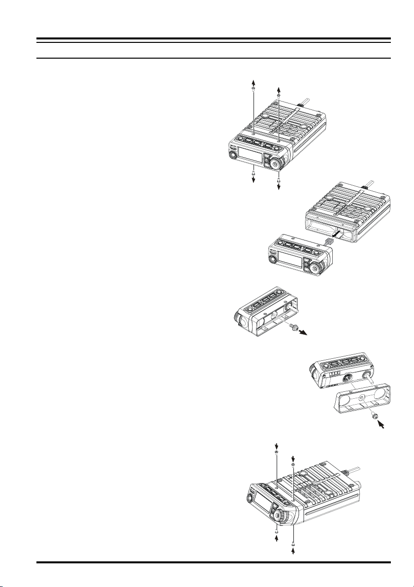
SEPARATE INSTALLATION
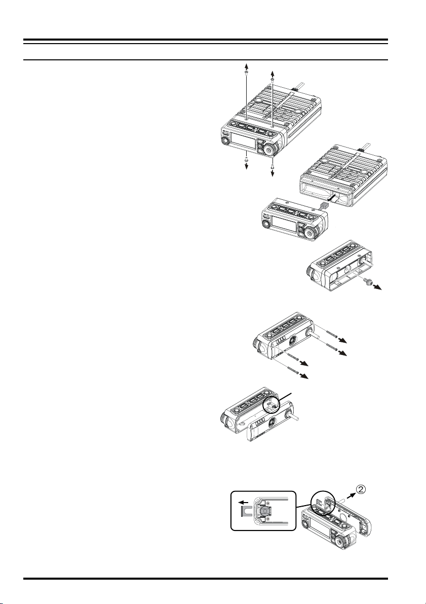
1. Remove the four screws securing the
Front Panel and then remove the Front
Panel from the Transceiver Body
(Figure 1).
2. Disconnect the 8-pin modular plug
from the Transceiver (Figure 2).
3. Remove the screw affixing the Straight
Sub Panel, and then remove the
Straight Sub Panel from the Front Panel
(Figure 3).
4. Remove the four screws securing the
Rear Case of the Front Panel and remove the Rear Case from the Front
Panel (Figure 4). Disconnect the Connector of the Connection Cable from
the Printed Circuit Board in the Front
Panel when you remove the Rear Case
(Figure 5).
5. Remove the Binding Plate from the
Rear Case (Figure 6-), and then pull
out the Connection Cable from the Rear
Case (Figure 6-).
Figure 1
Figure 2
Figure 3
Figure 4
connector
Figure 5
Figure 6
16 FTM-10R OPERATING MANUAL
Page 19
SEPARATE INSTALLATION
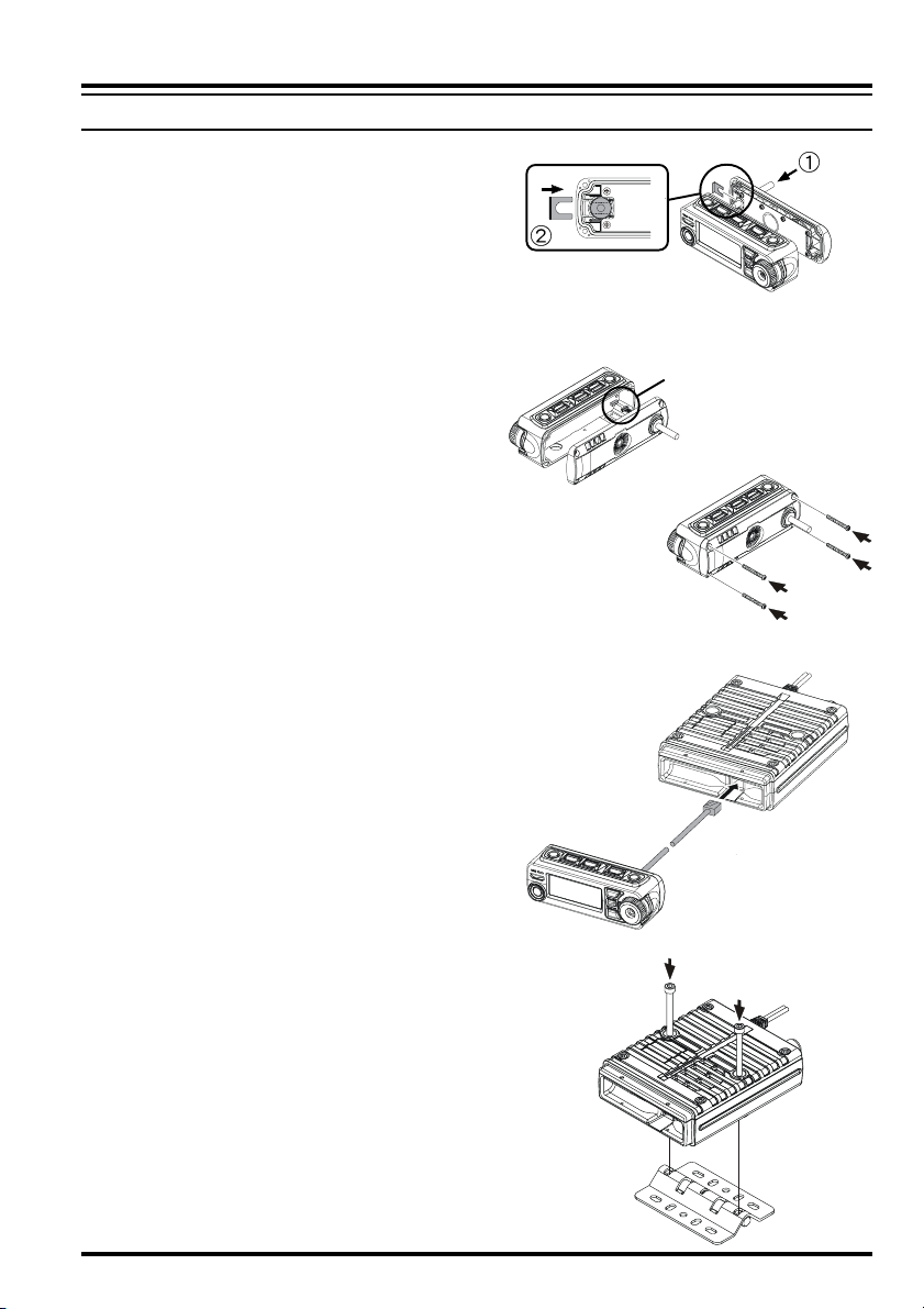
6. Insert the supplied 3-m Connection
Cable from the rear side of Rear Case
(Figure 7-), and then attach the Connection Cable to the Rear Case using
the previously removed Binding Plate
(Figure 7-).
6. Attach the Connection Cable to the
Printed Circuit Board (Figure 8), and
then replace the Rear Case to the Front
Panel using the previously removed
four screws (Figure 9).
7. Connect the 8-pin modular plug of the
Connection Cable to the Transceiver
(Figure 10).
9. Mount the supplied Mobile Mounting
Bracket to the any position using the
supplied screws (Figure 11).
INSTALLATION
Figure 7
connector
Figure 8
Figure 9
Figure 10
Figure 11
17FTM-10R OPERATING MANUAL
Page 20
INSTALLATION
SEPARATE INSTALLATION
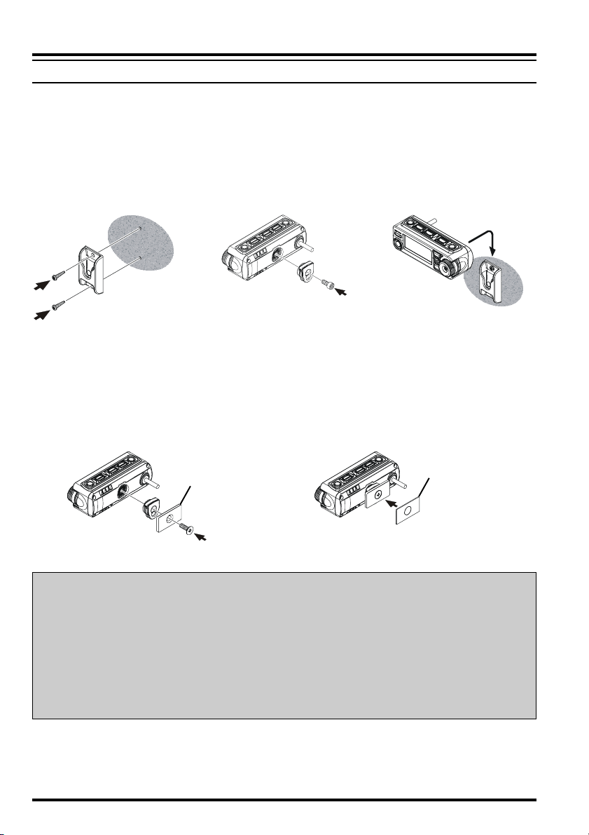
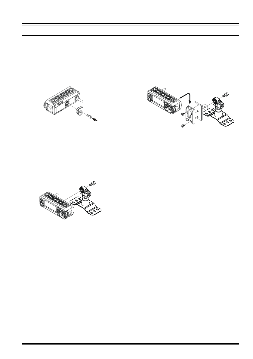
Front Panel Installation
Use the supplied Front Panel Bracket;
1. Mount the supplied
Front Panel Bracket to
the any positions using
the supplied two screws.
Use the supplied Magnet;
1. Connect the supplied Magnet and
Front Panel Hanger using the supplied screw .
2. Connect the supplied
Front Panel Hanger
using the supplied
screw.
Magnet
3. Install the Front Panel
into the Front Panel
Bracket.
2. Affix the supplied Protection Seal to
the Magnet.
Protection Seal
CAUTION!
PP
P If the protective film is not affixed to the magnet, it may damage the mounting
PP
surface.
PP
P Damage is possible even if the protection film is attached.
PP
PP
P Be careful handling the hanger. The strong magnet could pinch your fingers.
PP
PP
P Even with the strong magnet, it is possible to displace the bracket.
PP
PP
P The magnet may destroy data on banking & identification cards.
PP
18 FTM-10R OPERATING MANUAL
Page 21
SEPARATE INSTALLATION
Use the Optional Multi-Angle Bracket “MMB-M10”;
INSTALLATION
1. If you use the Front Panel as Microphone, Connect the supplied Front
Panel Hanger using the supplied
screw.
3. If you do not use the Front Panel as a
Microphone, install the Front Panel
directly to the “MMB-M10”.
2. Mount the supplied Front Panel
Bracket to the “MMB-M10” using the
supplied two screws.
19FTM-10R OPERATING MANUAL
Page 22
INSTALLATION
SEPARATE INSTALLATION
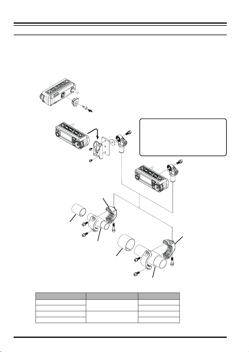
Use the Optional Handle Bar Bracket “MMB-M11”;
1. If you use the Front Panel as Microphone, Connect the supplied Front
Panel Hanger using the supplied
screw.
Bracket (S)
2. Bracket and Rubber are selected by
the size of installed Bar (Refer to the
table below).
If you do not use the Front Panel
as a Microphone, install the
Front Panel directly to the
“MMB-M11”.
Rubber (S-a: t=1 mm)
Bracket (L)
Rubber (S-b: t=2 mm)
Rubber (L-a: t=1 mm)
Rubber (L-b: t=3 mm)
Bar Bracket Rubber
7/8”
1” S-a
1-1/4”
1-1/2” L-a
S
L
S-a & S-b
L-a & L-b
20 FTM-10R OPERATING MANUAL
Page 23
INSTALLATION
Downloaded by
RadioAmateur.EU
NON-SEPARATE INSTALLATION
The FTM-10R front panel may be tilted using the supplied Angle Sub Panel.
1. Remove the four screws securing the
Front Panel and then remove the panel
from the transceiver body (Figure 1).
2. Disconnect the 8-pin modular plug
from the transceiver (Figure 2).
3. Remove the screw affixing the Straight
Sub Panel, and then remove the
Straight Sub Panel from the Front Panel
(Figure 3).
4. Attach the supplied Angle Sub Panel
to the Front Panel, using the previously
removed screw.
You may set this up in a “look-up” or
“look-down” configuration depending
on the mounting position of the Sub
Panel.
5. Connect the 8-pin modular plug to the
transceiver’s body.
6. Attach the Front Panel (with Angle Sub
Panel) to the transceiver’s body, using
the previously removed four screws
(Figure 5).
Figure 1
Figure 3
Figure 2
Figure 4
Figure 5
21FTM-10R OPERATING MANUAL
Page 24
BASIC OPERATION
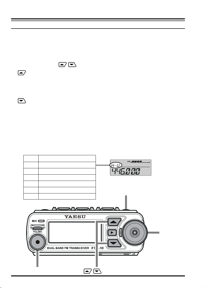
RECEIVE
1. To turn the transceiver on, press and hold in the top panel [POWER] key for two
seconds.
When you turn the transceiver on, the applied DC voltage is displayed on the LCD for
2 seconds. Then the operating frequency will be displayed.
To turn the transceiver off, press and hold in the [POWER] key for two seconds.
2. Press the front panel / keys to switch the operating band as follows:
Key
£ 2 m Amateur Band (H-V) £ 430 MHz Amateur Band (H-U) £ FM BC Band (FM) £
AM BC Band (AM) £ WX Band (WX) £ Audio LineÚ £ Group Memory (GRP) £ 2
m Amateur Band (H-V) £
Key
2 m Amateur Band (H-V) £ Group Memory (GRP) £ Audio LineÚ £ WX Band (WX)
£ AM BC Band (AM) £ FM BC Band (FM) £ 430 MHz Amateur Band (H-U) £ 2 m
Amateur Band (H-V) £
Ú When external audio equipment, like an iPod®, is connected, an after-market cable is
required.
When external audio equipment is connected, the input audio level must be adjusted
on the external audio equipment.
H-U 430 MHz Amateur Band
H-V 144 MHz Amateur Band
GRP Group Memory
-- Audio Line
WX WX Band
AM AM BC Band
FM FM BC Band
[
VOL/SEL] key
/ key
[
POWER] key
DIAL knob
22 FTM-10R OPERATING MANUAL
Page 25
BASIC OPERATION
3. Rotating the DIAL knob tunes the frequency in pre-programmed steps. Clockwise rota-
tion of the DIAL knob will increase the frequency; counter-clockwise rotation will lower
the operating frequency.
4. Press and hold in one of the front panel / keys for one second (the 1 MHz digit
will blink). Then rotate the DIAL knob to change the frequency at 1 MHz per step. This
feature is extremely useful for making rapid frequency excursions over the wide tuning
range of the FTM-10R.
5. Press the [VOL/SEL] key until the red LED to the left of the DIAL knob illuminates
and the volume level is displayed on the LCD. Now, the DIAL knob becomes the vol-
ume knob.
6. Rotate the DIAL knob to adjust the receiver volume. Clockwise rotation increases the
audio output level.
TRANSMISSION
1. Press the front panel / keys to switch the operating band to 144 MHz or 430
MHz band.
2. Press the PTT (Push To Talk) key on the front panel when the frequency is clear. Speak
into the microphone on the front panel (upper left corner of the front panel) in a normal
voice level.
When talking around 3 feet away from the front panel microphone, the modulation may
not be enough and the transmitted audio level may be lower.
3. When your transmission is complete, release the PTT key. The transceiver will revert to
the receive mode.
MIC
PTT key
23FTM-10R OPERATING MANUAL
Page 26
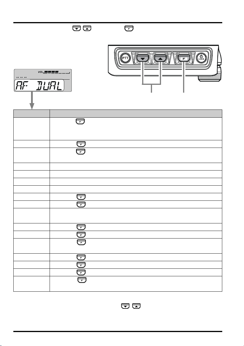
SMART MENU FEATURES
The FTM-10R top panel / keys, and the key select and enable operation of the
following features:
Select the function
Display Function
AF DUAL Press the key to activate the AF Dual function which enables receiv-
ing an Amateur Band signal while listening to the signal of an FM Broadcast Station at the same time.
ARTS Press the key to activate the ARTS feature.
DIMMER Press the key to enable adjustment of the display illumination level
by the DIAL knob.
HORN 1 Press the PTT switch to activate the sound of a Gong Bell.
HORN 2 Press the PTT switch to activate the sound of a UFO in flight.
HORN 3 Press the PTT switch to activate the sound of a klaxon.
HORN 4 Press the PTT switch to activate the sound of a siren.
INTERCOM Press the key to activate the Intercom mode.
MONI Press the key to disable noise and tone squelch.
PA Press the PTT switch to route your amplified voice through the PA
speaker.
REVERSE Press the key to activate the Reverse feature.
SCAN Press the key to activate the scanner.
SQL LEVL Press the key to enable adjustment of the noise squelch threshold
level by the DIAL knob.
SSCH Press the key to activate the Smart Search.
TCALL Press the key to activate the 1750 Hz Tone Burst.
TX POWER Press the key to change the transmit power level.
VOL.ITCOM Press the key to change the receiver audio level of the intercom
receiver.
[F]
key
Advice: When one of the above features does not appear in the list, it is because that feature
is not assigned to the top panel / keys. Please insure the Menu
“F14 FKEY MOD” is set to “FNC” or “FNC+MSG”.
24 FTM-10R OPERATING MANUAL
Page 27
SMART MENU FEATURES
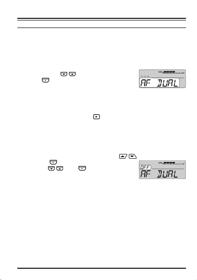
AF DUAL FUNCTION
With the “AF DUAL” function, it is possible to monitor your desired amateur band frequency while receiving AM, FM broadcast or Audio from the external input jack.
You may select: AM broadcast, FM broadcast, Club Channel or external line input, by
changing the Menu Item “F2 AF DUAL” (The factory default is AM broadcast receiving).
1. Set the FTM-10R to the desired amateur band frequency by the VFO or Memory chan-
nel selection.
2. Press the top panel / key to select “AF DUAL”.
3. Press the key to activate the AF Dual function.
P By first setting the desired VFO or memory channel in
step #1 above, and then starting “AF DUAL” function, both the amateur signals and
the AM broadcast station will be received.
4. Rotate the DIAL knob to select the desired AM Broadcast station.
P You may switch the AM Broadcast Band frequency control between the VFO and
Memory channel by pressing the key.
P When a signal is received in the amateur band, the AM Broadcast audio is muted.
When the amateur band signal drops, the AF Dual function is resumed (monitor the
amateur band frequency while receiving the AM broadcast).
P You may transmit on the frequency set in step1 by pressing the PTT key, even if the
AF Dual function is activated.
To disable the AF Dual function, press the front panel / keys.
P When the key function is set to “AF DUAL” via the
top panel / key, the key may be used to toggle
the “AF DUAL” on/off.
25FTM-10R OPERATING MANUAL
Page 28
SMART MENU FEATURES
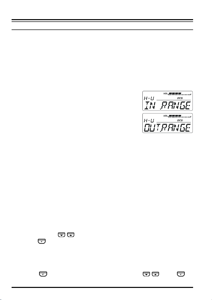
ARTS
The ARTS feature uses DCS signaling to inform both parties when you and another ARTS
equipped station are within communications range. This may be particularly useful during
Search and Rescue situations, where it is important to stay in contact with other members of
your group.
Both stations must set up their DCS codes to the same code number, then activate their
ARTS feature using the command appropriate for their radio. Alert ringers may be activated, if desired.
Whenever you push the PTT key, or every 25 seconds after ARTS is activated, your radio
will transmit a signal which includes a (subaudible) DCS code
for about 1 second. If the other radio is in range, the beeper
will sound (if enabled) and the display will show “IN.RANGE”,
otherwise the out of range display “OUT.RANGE” will be display during ARTS operation.
Whether you talk or not, the polling every 25 seconds will continue until you de-activate ARTS. When ARTS is de-activated,
DCS will also be deactivated (if you were not using it previously in non- ARTS operation).
If you move out of range for more than one minute (four pollings), your radio will sense
that no signal has been received. Three beeps will sound, and the display will revert to
“OUT.RANGE”. If you move back into range, your radio will again beep, and the display
will change back to the “IN.RANGE” indication.
TM
During ARTS operation, your operating frequency will continue to be displayed, but no
changes may be made to it or other settings. You must terminate ARTS in order to resume
normal operation. This is a safety feature designed to prevent accidental loss of contact due
to channel change, etc.
1. Set the FTM-10R to the desired amateur band frequency by the VFO or Memory channel selection.
2. Set your radio and the other radio(s) to the same DCS code number per the discussion
on page 65.
2. Press the top panel / key to select “ARTS”.
3. Press the key. You will observe the “OUT.RANGE” display on the LCD. The ARTS
operation has now commenced.
4. Every 25 seconds, your radio will transmit a “polling” call to the other station. When that
station responds with its own ARTS polling signal, the display will change to “IN.RANGE”
to confirm that the other station’s polling code was received in response to yours.
5. When the key function is set to “ARTS” via the top panel / key, the key
may be used to toggle the “ARTS” on/off.
26 FTM-10R OPERATING MANUAL
Page 29
SMART MENU FEATURES
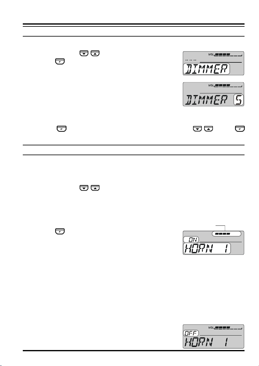
DIMMER FUNCTION
You may adjust the display dimmer level.
1. Press the top panel / key to select “DIMMER”.
2. Press the key.
3. Rotate the DIAL knob to select a comfortable brightness
level.
DIMMER 1 ÅÆ DIMMER 2 ÅÆ DIMMER 3
DIMMER 4 ÅÆ DIMMER 5
ÅÆ
Bright Dim
Å
4. Within two seconds of selecting the brightness level, save the new setting and return to
the VFO or Memory Channel mode.
When the key function is set to “DIMMER” via the top panel / key, the
key is used as the Dimmer Level control key.
HORN ALERT FEATURE
The Horn Alert feature outputs one of four unique sounds to the transceiver’s speaker.
When an optional MLS-200-M10 External Speaker is connected, the FTM-10R transceiver may be used as an 8 watt Horn Alert.
1. Press the top panel / key to select one of the four functions described below:
HORN 1: Sounds a Gong Bell.
HORN 2: Sounds a flight sound of a UFO.
HORN 3: Sounds a klaxon.
HORN 4: Sounds an ambulance siren.
2. Press the key to activate the Horn Alert feature.
When the Horn Alert function is activated, the volume level
graphic will be displayed on LCD.
3. Press the PTT key.
U You may change the PTT key function via Menu Item “F24 PTT MODE”.
MOMENT: While pressing the PTT key, the audio is output from the speaker (fac-
tory default).
TOGGLE: Once the PTT key is pressed the audio is output from the speaker, and
when the PTT key is pressed once again, the audio output is off.
U The unique sound, which was selected in step 1 above, will be output from the speaker.
U The “HORN OUT” notation appears in the display while the Horn Alert is activated.
U Press the [VOL/SEL] key to adjust the volume (AF level) of the Horn Alert output.
While the RED LED is on, the volume level can be adjusted with the dial knob.
U To disable the Horn Alert feature, repeat steps 1 and 2 above.
ÅÆ
Æ
(
Default “OFF”
)
Graphic Bar
27FTM-10R OPERATING MANUAL
Page 30
SMART MENU FEATURES
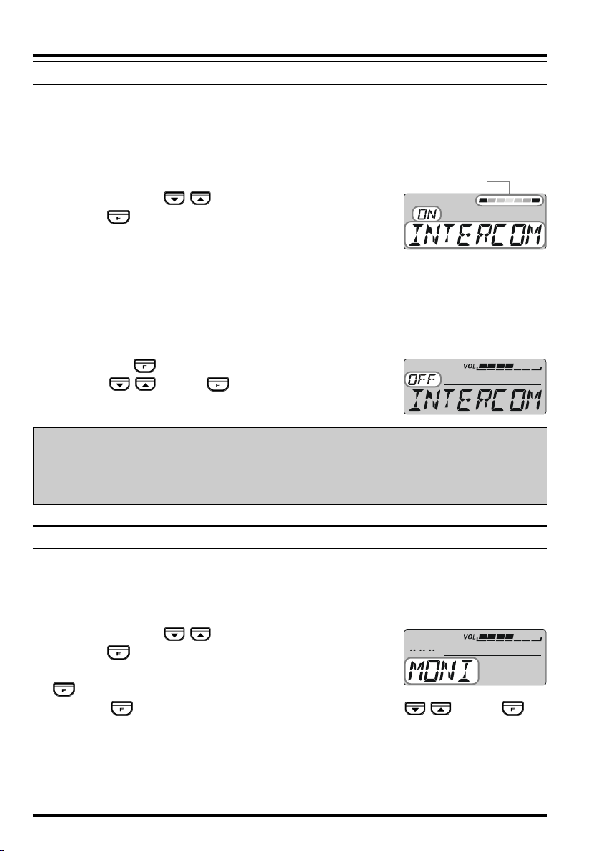
INTERCOM FUNCTION
Intercom operation is possible with the FT-10R, by installing the optional Bluetooth
Adapter unit “BU-1” in the radio and using the optional Bluetooth® Headset “BH-1”. When
operating in a very noisy environment, (for example, a loud exhaust or engine noise, or
inside an off-road vehicle) communication with a fellow passenger is possible using the
Bluetooth® intercom feature.
1. Press the top panel / key to select “INTERCOM”.
2. Press the key to activate the Intercom function.
When the Intercom function is activated, the volume level
graphic will be displayed on LCD.
You may switch the receiver audio volume level between “High” and “Low” via the
“VOL.ITCOM” function described below.
When the Intercom function is activated, the internal speakers (front panel and main
chassis) are disabled.
To disable the Intercom function, repeat steps 1 and 2 above.
When set the key function to “INTERCOM” via the
top panel / key, the key to be used as the Intercom feature on/off key.
Important Notice!
Graphic Bar
®
Use of a sound-isolating headset while driving on public roads is not lawful and hazardous. An open type headset must be used for safety.
MONITOR FEATURE
The Monitor permits disabling the noise and tone squelch systems temporarily.
When the received signal is weak and the sound from the speaker is intermittent, use this
function to over-ride the squelch and hear the received signal.
1. Press the top panel / key to select “MONI”.
2. Press the key.
The noise and tone squelch are disabled while pressing the
key.
When the key function is set to “MONI” via the top panel / key, the key
may be used as the “Monitor” key.
28 FTM-10R OPERATING MANUAL
Page 31

SMART MENU FEATURES
PUBLIC ADDRESS FEATURE
The Public Address feature enables the output of your voice to the transceiver’s speaker.
When an optional MLS-200-M10 External Speaker is connected, the FTM-10R allows
the transceiver to be used as an 8 W Public Address system.
1. Press the top panel / key to select “PA”.
2. Press the key to activate the Public Address feature.
3. Press the PTT key, and speak into the microphone in a nor-
mal voice level.
U You may select the PTT key function via Menu Item “F24 PTT MODE”.
MOMENT: While pressing the PTT key, the audio is output from the speaker (fac-
tory default).
TOGGLE: Once the PTT key is pressed the audio is output from the speaker, and
when the PTT key is pressed once again, the audio output is off.
U Your voice is output to the speaker.
U The “P A” notation appears in the display while the Public Address is activated.
U Press the [VOL/SEL] key to adjust the volume (AF level) of the PA output. While
the RED LED is on, the volume level can be adjusted with the dial knob.
CAUTION!
When the function is changed to the radio mode, the volume level remains the same.
Please be careful about the volume level setting.
Graphic Bar
U You may adjust the audio output level by rotating the DIAL knob while
To disable the Public Address feature, repeat steps 1 and 2 above.
Note: Please be careful that the PA function does not cause any
inconvenience or disturbance for others in your area.
REVERSE FEATURE
The Reverse feature reverses transmit and receive frequencies while working through a
repeater.
It is often helpful to be able to check the uplink (input) frequency of a repeater, to see if the
calling station is within direct (“Simplex”) range.
1. Press the top panel / key to select “REVERSE”.
2. Press the key to activate the Reverse feature.
The “ ” or “ ” or “ ” icon will blink while “Reverse”
shift is activated.
3. Press the key again to revert to the “Normal” shift direction.
29FTM-10R OPERATING MANUAL
Page 32

SMART MENU FEATURES
SCAN FEATURE
1. Press the top panel / key to select “SCAN”.
2. Press the key to initiate upward scanning.
When the scanner encounters a signal strong enough to open
the squelch, the scanner will halt for five seconds, and then
resume scanning.
3. To stop the scanner, press the or PTT key.
When the key function is set to “SCAN” via the top panel / key, the key
may be used as the scan start/stop command key.
If you want to change the direction of the scan while it is underway, rotate the DIAL
knob one click in the opposite direction (in this case, one click counter-clockwise). You
will see the scanner reverse direction and scan down in frequency.
The decimal point of the frequency display while the Scan is activated.
You may select the Scan Resume mode via the Menu Item “F26 RESUME”.
When you start the scanner in the memory mode, only the memorized memory channels
will be scanned
SMART SEARCHTM OPERATION
The Smart Search feature allows you to load frequencies automatically according to where
activity is encountered by your radio. When Smart Search is engaged, the transceiver will
search above and below your current frequency, storing active frequencies as it goes (without stopping on them even momentarily). These frequencies are stored into a special Smart
Search memory bank, consisting of 31 memories (15 above the current frequency, 15 below the current frequency, plus the current frequency itself). All channels where activity is
present will be loaded into the Smart Search memories. The search will stop after one
sweep in each direction, whether or not all 31 memories are filled.
Storing Smart Search Memories
1. Set the radio to the VFO mode. Be sure that you have the Squelch adjusted properly (so
that band noise is quieted).
2. Press the top panel / key to select “SSCH”.
3. Press the key to initiate upward scanning.
4. As active channels are detected, they will automatically be
stored into the Smart Search memory bank without causing the sweep to halt.
If you want to change direction of the Smart Search while it is underway, rotate the
DIAL knob one click in the opposite direction (in this case, one click counter-clockwise). You will see the scanner reverse direction and Smart Search down in frequency.
5. The Smart Search scan will eventually terminate, and the LCD will revert to Smart
Search Memory Channel “<C>”.
30 FTM-10R OPERATING MANUAL
Page 33

SMART MENU FEATURES
Number of Smart Search Memories.
<C> is the start frequency of the Smart Search.
6. To recall the Smart Search memories, just rotate the DIAL knob (or press the microphone’s
[UP]/[DWN] key) to choose from among the Smart Search memories.
7. Press the front panel key to return to VFO mode with the current frequency of the
Smart Search memory.
Note: 1) Smart Search is a great tool when visiting a city for the first time. You don’t
need to spend hours looking up repeater frequencies from a reference guidebook.
Just ask your FTM-10R where the action is!
2) The Smart Search memories are so-called “soft” memories. They will be lost if
you initiate a new Smart Search sweep of the band, or if you switch to the VFO or
Memory mode.
SQUELCH LEVEL ADJUST
Adjust the squelch level to mute the noise from the speaker when no signal is being received.
1. Press the top panel / key to select “SQL LEVL”.
The current squelch level will be displayed.
2. Press the key.
3. Rotate the DIAL knob just to the point where the noise is
silenced and the front panel green “
off.
Available selections are:
Amateur Bands:
OFF MIN 01 ~ 06 MAX (Default: 01)
AM/FM Broadcast Bands:
OFF MIN 01 ~ 03 MAX (Default; AM: 01, FM: 02)
If the DIAL knob is set further clockwise, sensitivity to weak signals is reduced.
4. Press the key to save the new setting and return to the VFO or Memory Channel
mode.
When the key function is set to “SQL LEVL” via the top panel / key, the
key may be used as the Squelch Level control key.
BUSYBUSY
BUSY” indicator turns
BUSYBUSY
31FTM-10R OPERATING MANUAL
Page 34

SMART MENU FEATURES
TCALL
You may enable TCALL if the repeaters in your country require a 1750-Hz burst tone for
access.
1. Press the top panel / key to select “TCALL”.
2. Press the key.
The transmitter will automatically be activated, and a 1750-Hz audio tone will be superimposed on the carrier.
3. You may release the key, and use the PTT key for activating the transmitter thereafter.
(
Default “OFF”
)
TX POWER SELECT
Set the TX Power level to reduce battery drain and use the lowest power necessary to
maintain reliable communications.
1. Press the top panel / key to select “TX POWER”.
2. Press the key repeatedly to select the desired transmit
power level.
You may set the transmit power level for the 144 MHz and
430 MHz band individually.
HIGH MID LOW
144 MHz 50 W
430 MHz 40 W
20 W 5 W
3. Two seconds after selecting the transmitter power level, the new setting is automatically
saved and the radio returns to the VFO or Memory Channel mode.
When the key function is set to “TX POWER” via the top panel / key, the
key may be used as the Transmit Power Level control key.
INTERCOM VOLUME CONTROL
1. Press the top panel / key to select “VOL.ITCOM”.
2. Press the key to change the Intercom receiver audio volume level between “HIGH”
and “LOW”.
3. Two seconds after selecting the Intercom receiver audio volume level, the new setting is
automatically saved and the radio returns to the VFO or Memory Channel mode.
When the key function is set to “VOL.ITCOM” via the top panel / key, the
key may be used as the Transmit Power Level control key.
32 FTM-10R OPERATING MANUAL
Page 35

MEMORY OPERATION
Many memory resources are available on the FTM-10R. A total of 500 memories are available, and each may be appended with an alphanumeric label of up to eight characters, for
quick channel recognition.
The FTM-10R has two methods of the Memory Mode; (1) Group Memory Mode enables
the recall of all memory channels, and (2) In-band Memory Mode enables the recall of
memory channels, which are stored in the same operating band.
MEMORY STORAGE
To store a frequency into memory:
1. Press the front panel / keys to select the desired operating band.
2. Rotate the DIAL knob to select the desired operating frequency.
3. Press and hold in the key for one second.
A “MIN” notation will appear on the display and the frequency display will blink.
After 5 seconds of pressing the key, will return to the
VFO mode.
4. Within 5 seconds of pressing the key, press the key again, this time briefly, to
store the displayed data into the memory channel slot. The “MIN” notation will disappear (since you are still operating in the VFO mode).
U A “MIN” notation will appear on the display and the frequency display will blink.
U The FTM-10R will automatically store the channel frequency and data into the va-
cant memory channel.
U FTM-10R can memorize the following items with the frequency at the same time:
P Memory Group Information
P Alpha-numeric Memory Channel Tag
P Repeater Shift (Direction and Shift Frequency)
P CTCSS/DCS Squelch System and its frequency and code
P Transmit Output Power Level
P Scan Mode (Skip Scan or Preferential Scan)
P Frequency Step
P Semi-Duplex (Odd) frequency
P Receiving Mode (AM or FM)
Important Note: On rare occasions the memorized data may become corrupted by miss
operation, or static electricity. When repairs are made the memory data
may be lost. Please write down or record the memorized information so
you will be able to restore it if needed.
33FTM-10R OPERATING MANUAL
Page 36

MEMORY OPERATION
MEMORY RECALL
Once you have stored the desired memories, you may switch from “VFO” mode to “Memory
Recall” mode, and operate on just the stored memory channels.
The FTM-10R has two methods of recalling the memory. (1) Group Memory Mode enables you to recall all the Memory Channels and (2) In-band Memory Mode enables you to
recall only the memory channels which are stored within the same operating band.
All Memory Channel Recall (Group Memory Mode)
1. To recall the Group Memory bank, press the front panel
/ keys until the “GRP” notation appears at the upper left corner in the display for a moment. This indicates
that the “Group Memory bank” is now recalled.
2. Rotate the DIAL knob to select the desired memory channel. You may recall any of the
channels stored in the FTM-10R memories.
3. To exit from the Memory Recall mode, press the front panel / keys to select the
desired operating band.
Important Note: The memory channel is assigned to a Group Memory bank automatically.
You may assign/eliminate the memory channel to/from the Group Memory
bank. See page 36 for details of the operation.
Recall a memory channel which is stored in the same operating band
(In-band Memory Mode)
1. Press the front panel / keys to recall the desired operating band.
If you want to recall the 144 MHz band’s memory channel, press the front panel
/ keys to recall the “H-V” icon.
If you want to recall the 430 MHz band’s memory channel, press the front panel
/ keys to recall the “H-U” icon.
2. Press the front panel key briefly. A “-MEMORY-” notation will appear on the display
for a moment. This indicates that the “Memory Recall” mode is now engaged.
3. Rotate the DIAL knob to select the desired memory channel. You may recall a memory
channel which is stored in the same operating band of the FTM-10R.
4. To exit from the Memory Recall mode, press the front panel key to return to the
VFO mode.
34 FTM-10R OPERATING MANUAL
Page 37

MEMORY OPERATION
MEMORY CHANNEL CUSTOMIZATION
The memory channel data can be customized using the following functions.
Example : Select the “
No.
M1
M2
M3
M4
M5
M6
M7
M8
M9
M10
M11
M12
M13
Diaplay
GROUP
MEM CH
MEM SORT
MEM TAG
SCN TYPE
SKIPONLY
SQL LEVL
SQL TSQF
SQL DCS
SQL TYPE
TX SHIFT
TX POWER
DELETE
M 1 GROUPM 1 GROUP
M 1 GROUP”
M 1 GROUPM 1 GROUP
Function
Assigns/Eliminates the memory channel to/from the Memory
Group Memory bank.
Changes the memory channel number to the desired vacant
memory channel number.
Sorts and renumbers the Memory Channels by frequency, from
low to high.
Appends an Alphanumeric “Tag” (label) to a memory channel.
Sets the Scan Type (Skip Memory or Preferential Memory).
Set the Preferential Scan List.
Sets the Squelch Threshold Level.
Change the CTCSS Tone Frequency.
Change the DCS Code.
Change the Squelch Type (CTCSS or DCS).
Stores an independent (in band) transmit frequency (Odd Split).
Change the Transmitter Power Level.
Deletes memorized data (except CLUB memory channel).
35FTM-10R OPERATING MANUAL
Page 38

MEMORY OPERATION
MEMORY GROUP BANK
In the FTM-10R, the memory channel is assigned to the Group Memory Bank automatically. The Group Memory Bank can be recalled by pressing the front panel / key (A
“GRP” notation appears at the upper left corner in the display for a moment.). You may
observe the Group Memory Bank between the Audio Line and 2 m Amateur Band.
You may assign/eliminate the memory channel to/from the Group Memory Bank. The eliminated memory channel is only recalled by recalling the memory channel, which is stored in
the same operating band.
To eliminate the memory channel from the Group Memory bank:
1. Recall the memory channel you wish to delete from the Group Memory Bank.
2. Press and hold the key for one second to enter the Memory Channel Customization
mode.
3. Rotate the DIAL knob to select Menu Item “M1 GROUP.”
Press the key briefly, then rotate the DIAL knob to select “OFF;” this deletes the current memory channel from
the Group Memory bank).
4. Press the [VOL/SEL] key to save the new setting and return to the memory recall mode.
To re-assign the eliminated memory channel into the Group Memory bank:
1. Press the front panel key to switch the VFO mode, if needed.
2. Press the front panel / keys to recall the operating band which is the same band
as the eliminated memory channel.
3. Press the front panel key again to switch the “Memory Recall” mode, and then
rotate the DIAL knob to select the memory channel you wish to re-assigned into the
Group Memory bank.
4. Press and hold the key for one second to enter the Memory Channel Customization
mode.
5. Rotate the DIAL knob to select Menu Item “M1 GROUP.”
6. Press the key briefly, then rotate the DIAL knob to select “
channel will be assigned into the Group Memory bank.
7. Press the [VOL/SEL] key to save the new setting and return to the memory recall mode.
ONON
ON;” The current memory
ONON
36 FTM-10R OPERATING MANUAL
Page 39

MEMORY OPERATION
MEMORY CHANNEL NUMBER CHANGE
You may change the memory channel number to a desired vacant memory channel manually.
1. Recall the memory channel on which you wish to change the Memory Channel number.
2. Press and hold the key to enter the Memory Channel Customization mode.
3. Rotate the DIAL knob to select Menu Item “M2 MEM CH.”
4. Press the key briefly. The current memory channel num-
ber will appear in the display.
5. Press and hold the key for one second.
6. Rotate the DIAL knob to select the desired memory chan-
nel number.
If you decide to cancel the Memory Channel Number
Change, press the [VOL/SEL] key.
If the channel number is blinking, that channel is currently
“occupied” by other frequency data, and you should not
select that channel.
7. Press and hold the key to change the Memory Channel Number.
8. Press the [VOL/SEL] key to save the new setting and return to the memory recall mode.
MEMORY CHANNEL SORT
You may sort and renumber the Memory Channels by frequency, from low to high:
1. Press the front panel key to switch the Memory Recall mode, if needed.
2. Press and hold the key for one second to enter the Memory Channel Customization
mode.
3. Rotate the DIAL knob to select Menu Item “M3 MEM
SORT.”
4. Press the key briefly, to display the confirmation mes-
sage (“SORT Y”) on the LCD.
If you decide to cancel the Memory Channel Sort, press the
[
VOL/SEL] key.
5. Press and hold the key for one second to display the
message (“SORTING”) on the LCD, then the FTM-10R is
reset automatically and sorting is complete.
37FTM-10R OPERATING MANUAL
Page 40

MEMORY OPERATION
LABELING MEMORY
You may wish to append an Alphanumeric “Tag” (label) to a memory or memories, to aid in
recollection of the channel’s use (such as a club name, etc.). This is easily accomplished
using the Set (Menu) mode.
1. Recall the memory channel on which you wish to append a label.
2. Press and hold the key for one second to enter the Memory Channel Customization
mode.
3. Rotate the DIAL knob to select Menu Item “M4 MEM TAG.”
4. Press the key briefly, then rotate the DIAL knob to select “ALPHA.”
5. Press and hold the key for one second to display the
previous label.
6. Press the PTT key to clear any previous label, if needed.
7. Rotate the DIAL knob to select the first digit of the desired label.
8. Press the key to move to next character.
9. Repeat steps 6 and 7 to program the remaining letters, numbers, or symbols of the
desired label. A total of eight characters may be used in the creation of a label.
10. If you make a mistake, press the key to backspace the cursor, then re-enter the
correct letter, number, or symbol.
Press the PTT key to delete all data after the cursor that may have been previously
stored erroneously.
11. When you have programmed a label that is under eight characters, press and hold in the
key for one second, until the “ALPHA” notation appears.
12. Press the [VOL/SEL] key to save the label and return to the memory recall mode. The
labeled (Alpha-Numeric Tag) will now be displayed.
To disable the Alpha-Numeric Tag (enabling the frequency display):
1. Recall the memory channel on which you wish the frequency to display.
2. Press and hold the key for one second to enter the Memory Channel Customization
mode.
3. Rotate the DIAL knob to select Menu Item “M4 MEM TAG.”
4. Press the key briefly. Then, rotate the DIAL knob to select “FREQ.”
5. Press the [VOL/SEL] key to return to the memory recall mode. The memory channel
frequency will now be displayed.
38 FTM-10R OPERATING MANUAL
Page 41

MEMORY OPERATION
SCAN TYPE
The FTM-10R has two methods of performing Memory Channel Scan; (1) All Memory
Channel Scanning and (2) Scanning only memory channels which are selected via the Skip/
Preferential memory setting (see next step).
1. Press the front panel key to switch the Memory mode, if needed.
2. Press and hold the key for one second to enter the Memory Channel Customization
mode.
3. Rotate the DIAL knob to select Menu Item “M5 SCN TYPE.”
4. Press the key briefly.
5. Rotate the DIAL knob to select desired Scan Type:
ALL MEM: The FTM-10R scans on all Memory Chan-
nels.
ONLY MEM: The FTM-10R scans only the memory chan-
nels that are appended with the “ONLY” flag
via the Skip/Preferential memory setting.
6. Press the [VOL/SEL] key to return to the memory recall
mode. The memory channel frequency will now be displayed.
SKIP/PREFERENTIAL SCAN SETTING
The FTM-10R allows you to set up a “Preferential Scan List”. You can “flag” channels
within the memory system. When you initiate the Preferential Memory Scan, only “flagged”
channels will be scanned.
1. Recall the memory channel that you wish to skip. (or Preferential Memory Channel).
2. Press and hold the key for one second to enter the Memory Channel Customization
mode.
3. Rotate the DIAL knob to select Menu Item “M6 SKIPONLY.”
4. Press the key briefly.
5. Rotate the DIAL knob to select the desired Scan Type:
SKIP: This memory channel is skipped during memory
channel scans.
ONLY: This memory channel scans during preferential
memory scans.
OFF: This memory channel scans during memory chan-
nel scan.
6. Press the [VOL/SEL] key to return to the memory recall mode. The memory channel
frequency will now be displayed.
39FTM-10R OPERATING MANUAL
Page 42

MEMORY OPERATION
SQUELCH LEVEL
The FTM-10R allows setting the squelch threshold level.
1. Press the front panel key to switch the Memory mode, if needed.
2. Press and hold the key for one second to enter the Memory Channel Customization
mode.
3. Rotate the DIAL knob to select Menu Item “M7 SQL LEVL”.
4. Press the key briefly. Then rotate the DIAL knob to
select the desired squelch threshold level (“SQL OFF” ~ “SQL
MAX”).
5. Press the [VOL/SEL] key to save the new setting and return to the memory recall mode.
CTCSS FREQUENCY
The FTM-10R enables you to change the CTCSS Tone frequency.
1. Recall the memory channel on which you wish to change the CTCSS Tone Frequency.
2. Press and hold the key for one second to enter the Memory Channel Customization
mode.
3. Rotate the DIAL knob to select Menu Item “M8 SQL TSQF”.
4. Press the key to display the current CTCSS Tone Frequency.
5. Rotate the DIAL knob to select desired CTCSS Tone Frequency.
6. Press the [VOL/SEL] key to save the new setting and return to the memory recall mode.
CTCSS TONE FREQUENCY (Hz)
67.0
69.3
71.9
74.4
77.0
79.7
82.5
85.4
88.5
91.5
94.8
97.4
100.0
103.5
107.2
110.9
114.8
118.8
123.0
127.3
131.8
136.5
141.3
146.2
151.4
156.7
159.8
162.2
165.5
167.9
171.3
173.8
177.3
179.9
183.5
186.2
189.9
192.8
196.6
199.5
203.5
206.5
210.7
218.1
225.7
229.1
233.6
241.8
250.3
254.1
40 FTM-10R OPERATING MANUAL
Page 43

MEMORY OPERATION
DCS CODE
The FTM-10R enables you to change the DCS Tone Code.
1. Recall the memory channel on which you wish to change the DCS code.
2. Press and hold the key for one second to enter the Memory Channel Customization
mode.
3. Rotate the DIAL knob to select Menu Item “M9 SQL DCS”.
4. Press the key to display the current DCS Code.
5. Rotate the DIAL knob to select desired DCS Tone Code.
6. Press the [VOL/SEL] key to save the new setting and re-
turn to the memory recall mode.
DCS CODE
023
047
073
131
156
223
251
271
332
371
445
465
532
631
723
025
051
074
132
162
225
252
274
343
411
446
466
546
632
731
026
053
114
134
165
226
255
306
346
412
452
503
565
654
732
031
054
115
143
172
243
261
311
351
413
454
506
606
662
734
032
065
116
145
174
244
263
315
356
423
455
516
612
664
743
036
071
122
152
205
245
265
325
364
431
462
523
624
703
754
043
072
125
155
212
246
266
331
365
432
464
526
627
712
-
CTCSS/DCS OPERATION
The FTM-10R enables you to change the CTCSS/DCS operation (CTCSS/DCS mode,
CTCSS Tone frequency, and DCS Tone Code) that was set previously.
1. Recall the memory channel on which you wish to change the CTCSS/DCS operation.
2. Press and hold the key for one second to enter the Memory Channel Customization
mode.
3. Rotate the DIAL knob to select Menu Item “M10 SQL
TYPE”.
4. Press the key to display the current CTCSS/DCS op-
eration mode.
5. Rotate the DIAL knob to select desired CTCSS/DCS operation mode.
TONE ENC: Activates the CTCSS Encoder
TONE SQL: Activates the CTCSS Encoder/Decoder
REV TONE: Activates the Reverse CTCSS Decoder (Mutes receiver when matching tone
is received)
DCS: Activates the Digital Coded Encoder/Decoder
OFF: Disable the CTCSS/DCS operation
6. Press the [VOL/SEL] key to save the new setting and return to the memory recall mode.
41FTM-10R OPERATING MANUAL
Page 44

MEMORY OPERATION
STORING INDEPENDENT TRANSMIT FREQUENCY (ODD SPLIT
All memories can store an independent (in band) transmit frequency.
The FTM-10R has two methods of the Storing Independent Transmit Frequency; (1) Using
the Standard Repeater Shift and (2) Using the Odd Split Memory for operation on repeaters
with non-standard shift.
)
Using the Standard Repeater Shift
1. Recall the memory channel on which you wish to store the Independent Transmit Frequency.
2. Press the key to enter the memory mode. Then recall the memory channel on which
you wish to store the Independent Transmit Frequency.
3. Press and hold the key for one second to enter the Memory Channel Customization
mode.
4. Rotate the DIAL knob to select Menu Item “M11 TX SHIFT”.
5. Press the key briefly.
6. Rotate the DIAL knob to select desired shift direction. Available selections are “RPTR -”, “RPTR +”, and “SIMPLEX”.
7. Press the [VOL/SEL] key to save the new setting and return to the memory recall mode.
Whenever you recall a memory which contains independently stored transmit and receive frequencies, the “ ” indication will appear on the display.
Using the Odd Split Memory
1. In VFO mode, tune to your desired transmit frequency. (Your transmit frequency should
be in the same band as the receive frequency).
2. Press the key to enter the memory mode. Then recall the memory channel on which
you wish to store the Independent Transmit Frequency.
3. Press and hold the key for one second to enter the Memory Channel Customization
mode.
4. Rotate the DIAL knob to select Menu Item “M11 TX SHIFT”.
5. Press the key briefly.
6. Rotate the DIAL knob to select “S-DUPLEX”.
7. Press the [VOL/SEL] key to save the new setting and return to the memory recall mode.
Whenever you recall a memory which contains independently stored transmit and receive frequencies, the “ ”
indication will appear on the display.
42 FTM-10R OPERATING MANUAL
Page 45

MEMORY OPERATION
TRANSMITTER POWER LEVEL
The FTM-10R enables you to set the Transmitter Power Level for each memory channel
individually.
1. Recall the memory channel on which you wish to set the Transmitter Power Level.
2. Press and hold the key for one second to enter the Memory Channel Customization
mode.
3. Rotate the DIAL knob to select Menu Item “M12 TX
POWER”.
4. Press the key briefly to display the current Transmitter
Power Level.
5. Rotate the DIAL knob to the select desired Transmitter Power Level (“LOW”, “MID”, or
“HIGH”).
6. Press the [VOL/SEL] key to save the new setting and return to the memory recall mode.
HIGH MID LOW
144 MHz 50 W
430 MHz 40 W
DELETING MEMORY
You may delete the memorized data (except CLUB memory channel) of the FTM-10R
memories.
20 W 5 W
1. Recall the memory channel on which you wish to delete.
2. Press and hold the key for one second to enter the Memory Channel Customization
mode.
3. Rotate the DIAL knob to select Menu Item “M13 DELETE”.
4. Press the key briefly to display the confirmation mes-
sage (“DELETE Y”) on the LCD.
If you decide to cancel the Memory Channel Number
Change, press the [VOL/SEL] key.
5. Press and hold the key for one second. The display will
revert to memory mode.
Note: Once deleted, the channel data can not be recovered.
43FTM-10R OPERATING MANUAL
Page 46

CLUB CHANNEL OPERATION
The FTM-10R has a special memory channel called “Club Channel”, and the following
features can be handy.
The “Club Channel” is displayed at the first of the Group
Memory Bank and “CLB” is indicated when the channel is recalled. The Club Channel can also be reprogrammed.
U Monitoring the “Club Channel” periodically. (Club Channel Monitor function)
There are two (2) methods for this feature.
1. While monitoring the other memory channel, periodically checking the “Club Chan-
nel”. (See below)
2. While listening to the AM or FM broadcast stations or the external audio input sig-
nal , periodically checks the “Club Channel”. (See page 62)
U Message transmission function (See page 46)
U Duplicate the memorized messages and the ID of the members registered in the radio.
(Message Clone function. See page 48)
U Duplicate the memory channel and other setting information to other radios. (Clone
function. See page 50)
Recalling the Club Channel
1. Press the front panel / key to recall the Group
Memory Bank (“GRP” notation will appear at the upper
left corner in the display for a moment).
When the display indicates the Clock, Stop Watch Timer,
or Temperature, press the [VOL/SEL] key to change to the VFO or memory mode, then
perform the above selection.
2. Rotate the DIAL knob to select the Club Channel (The “CLB”
notation will appear at the upper left corner in the display
for a moment, then change to “GRP” notation).
You may change the Club channel frequency to your desired frequency.
Activating the Club Channel Monitor
This function monitors the “Club Channel” periodically once each 3 seconds while listening to another memory channel or a VFO frequency. Once a signal is received on the “Club
Channel”, the FTM-10R automatically receives the “Club Channel” signal continuously
until the signal disappears.
Note: The “Club Channel” is only watched once per 3 seconds, and a signal sent on the
“Club Channel” may be missed. If the “Club Channel” needs to be monitored with
higher priority, this mode is not recommended. Please note that while listening to the
AM or FM broadcast band or the external audio input signal, the “Club Channel” is
44 FTM-10R OPERATING MANUAL
Page 47

CLUB CHANNEL OPERATION
watched periodically, and the signal on the “Club Channel” is received.
When “Club Channel” function is activated, a noise may be heard every time the
“Club Channel” is watched (once per 3 seconds). This noise is caused by checking
the “Club Channel” for any signals. This is not a problem or defect of the radio.
1. Press and hold the [VOL/SEL] key for one second to activate the Menu mode.
If the display indicates the Clock, Stop Watch Timer, or Temperature, press the [VOL/
SEL] key and change to the VFO or memory mode, then perform above step.
2. Rotate the DIAL knob to select Menu Item “F10 CLUB PRI”.
3. Press the key to enable selection of this Menu Item.
4. Rotate the DIAL knob to select the desired operating mode:
AUTO: The FTM-10R checks the “Club Channel” each 3
seconds. When a signal is received on the “Club
Channel”, the FTM-10R will monitor the channel
until the signal drops. When the signal drops, the
FTM-10R will resume checking the “Club Channel” each 3 seconds.
HOLD: When a signal is received on the “Club Channel”, the FTM-10R receives the
“Club Channel” continuously, and will not restart the “Club Channel” monitor.
OFF: Disables the Club Channel Monitor feature.
5. Press the [VOL/SEL] key for one second to save the new setting and activate Club
Channel Monitor.
When the Club Channel Monitor is activated, the “PRI” icon will appear (if receiving
on the VFO or memory channel) or blink (if receiving on the “Club Channel”) on the
display.
When the PTT key is pressed, the FTM-10R will transmit on the “Club Channel”.
You may change the VFO frequency or memory channel while Club Channel Monitor
is active.
6. To disable the Club Channel Monitor, select “OFF” as in step 4 above.
Return to the VFO or Memory Channel mode.
When the “AUTO” mode is selected in step 4 above, press the key to return to the
VFO or Memory Channel mode while receiving the “Club Channel”.
The difference between “Club Channel Monitor” and “AF DUAL” feature.
(1) “Club Channel Monitor” feature watches a club channel each 3 seconds while
listening to the AM/FM broadcast, audio and an amateur band signal is received.
(2) “AF DUAL” feature always receives the club channel, even if listening to the AM/
FM broadcast, audio and an amateur band signal is received. Two receivers are
included. One is for AM/FM receiving, audio and the other is for the amateur
bands. You cannot miss a signal on the Club Channel, anytime.
45FTM-10R OPERATING MANUAL
Page 48

MESSAGE FEATURE
While operating on the Club Channel, a message (up to 16 characters) can be sent, instead of
sending a voice. 20 kinds of messages can be programmed, and one of them can be selected
and transmitted with your ID.
Note: The Message Feature requires that all members (1) use the FTM-10R transceiver, (2)
store the same messages into the message slot, (3) store the same member list into the
member box, and (4) store the desired coordination frequency into the “Club Channel”.
Does not send the Message through the repeater.
Does not activate the Message Feature, when the CTCSS, DCS, or Pager is activated.
PROGRAMMING A MESSAGE
(Requires all members to set the same message into the same message slot in the same order.)
The FTM-10R has 20 message slots, including a factory-programmed message (EMER-
GENCY). The factory-programmed message of course can be overwritten at any time with
personalized messages.
1. Press and hold the [VOL/SEL] key for one second to activate the Menu mode.
When the display indicates the Clock, Stop Watch Timer, or Temperature, press the
[
VOL/SEL] key to change to the VFO or memory mode, then perform above.
2. Rotate the DIAL knob to select Menu Item “F18 MESSAGE”.
3. Press the key to enable selection of this Menu Item.
4. Rotate the DIAL knob to select the desired Message slot
into which you wish to store a message. The LCD displays
the previously stored message.
5. Press and hold the key for one second.
Press the PTT key to clear the previously stored message,
if desired.
6. Rotate the DIAL knob to select the first character of the
message you wish to store, and then press the key briefly
to save the first character of the message and move on to
the next place.
7. Repeat the previous step to complete the message (up to 16
characters). If you make a mistake, press the key to move back to the incorrect
character, then re-enter the correct character.
Press the PTT key to delete all data after the cursor that may have been previously
stored erroneously.
8. When the Message entry is complete, press and hold in the key for one second.
If you decide to cancel programming a message, press the [VOL/SEL] key to exit to
normal operation.
9. If you wish to store another message, repeat steps 4 through 8 above.
10. Press the [VOL/SEL] key to save the new setting and exit to normal operation.
Number of Message
46 FTM-10R OPERATING MANUAL
Page 49

MESSAGE FEATURE
PROGRAMMING A MEMBER LIST
(Requires all members set the same member list (includes own ID) into the same member
box in the same order.)
It is possible to register a maximum of 20 persons, in order to identify the sender. When
you receive a message transfer, you can know who sent the message by the ID in the register. In addition, your ID can be sent to the members when you transmit any messages to
them.
If all the members share the register information (ID), the message sender ID will be shown
on the display when receiving the message.
Even if no IDs are registered, the function can work. In this case “MEMBER 1” though
“MEMBER 20” will be displayed, when receiving a message.
We recommend that you use your call sign for the member list.
1. Press and hold the [VOL/SEL] key for one second to activate the Menu mode.
When the display indicates the Clock, Stop Watch Timer, or Temperature, press the
[
VOL/SEL] key to change to the VFO or memory mode, then perform the above step.
2. Rotate the DIAL knob to select Menu Item “F16 ID LIST”.
3. Press the key to enable selection of this Menu Item.
4. Rotate the DIAL knob to select the desired member box (1
~ 20) into which you wish to store a member ID. The LCD
will display the previously stored member ID.
5. Press and hold the key for one second.
Press the PTT key to clear the previously stored message,
if desired.
6. Rotate the DIAL knob to select the first character of the
personal ID you wish to store, and then press the key
briefly to save the first character of the personal ID and
move on to the next place.
7. Repeat previous step to complete the personal ID (up to 8
characters). If you make a mistake, press the key to
move back to the incorrect character, then re-enter the correct character.
Press the PTT key to delete all data after the cursor that may have been previously
stored erroneously.
8. When the personal ID entry is complete, press and hold in the key for one second.
If you decide to cancel programming a message, press the [VOL/SEL] key, exit to
normal operation.
9. If you wish to store another personal ID, repeat steps 4 through 8 above.
10. Press the [VOL/SEL] key to save the new setting and exit to normal operation.
Number of Member box
47FTM-10R OPERATING MANUAL
Page 50

MESSAGE FEATURE
CLONING THE MESSAGE
It is possible to copy/duplicate the programmed messages, and all the IDs of the members,
when using the “Message” function.
If messages (max 20 messages) and IDs (max 20 persons) are programmed in only one
transceiver (FTM-10R), the information can be copied to the transceivers of all members at
once, without connecting any cables.
Note: This message clone function will only operate using the Club Channel frequency in
the 440 MHz amateur band.
Recall and monitor the Club Channel frequency. If the channel is busy and any signal
is heard, the message clone function cannot work correctly. Change the Club Channel to a frequency not in use, and clone the messages and the IDs.
Preparations (Source Transceiver)
1. Turn the transceiver off.
2. Press and hold the PTT key while turning the power on
again.
3. The “TX CLONE” notation and the Club Channel frequency
appear on the display alternately.
Preparations (Destination Transceiver)
1. Turn the transceiver off.
2. Press and hold the [VOL/SEL] key while turning the power
on again.
3. Rotate the DIAL knob to select the “SF2 COPY MSG”.
Cloning
1. Bring the Source Transceiver and the Destination Transceiver as close as possible.
2. Press the top panel key on the Source Transceiver.
The Destination Transceiver does not require any set up operation.
When receiving clone data from the “Source Transceiver”, the “Destination Transceiver”
automatically stores all the data. The LED blinks for 3 seconds with a blue color, then
displays “MSG” and “RECEIVED” on the LCD. The “Destination Transceiver” automatically turns off and on, then returns to normal operation and mode set before the
Clone operation began. The copy/clone procedure is completed.
After completion of the copy/cloning, set your “MY ID” (see page 49). By setting the “MY
ID”, your ID will be displayed with the messages you send.
If “ERROR” is displayed on the LCD screen during the Clone procedure, the cloning has
not completed correctly. In this case, first turn the radio off and back on, then try the cloning
procedure again. In this case, please be aware the following notice.
P The distance between the source transceiver and destination transceiver must be close.
P Signals on the Club Channel frequency may interrupt the data transfer.
P Any equipment that generates electrical noise may interrupt the data transfer.
48 FTM-10R OPERATING MANUAL
Page 51

MESSAGE FEATURE
SET YOUR PERSONAL ID
To choose your personal ID from the member list.
1. Press and hold the [VOL/SEL] key for one second to activate the Menu mode.
When the display indicates the Clock, Stop Watch Timer, or Temperature, press the
[
VOL/SEL] key to change to the VFO or memory mode, then perform the above step.
2. Rotate the DIAL knob to select Menu Item “F17 ID REG”.
3. Press the key to enable selection of this Menu Item.
4. Rotate the DIAL knob to select the member box (1 ~ 20)
where your ID is stored.
5. Press the [VOL/SEL] key to save the new setting and exit
to normal operation.
SENDING A MESSAGES
The registered message can be sent to the members who are receiving the Club Channel.
When a message is sent, the transmitter's ID will be sent also, and the receiver can identify
who sent the message.
Note: This “Message” function is only available on the Club Channel.
The “MY ID” setting (see above) is required for the transmitter’s ID to be shown with
the received message.
1. Press and hold the [VOL/SEL] key for one second to activate the Menu mode.
When the display indicates the Clock, Stop Watch Timer, or Temperature, press the
[
VOL/SEL] key to change to the VFO or memory mode, then perform above step.
2. Rotate the DIAL knob to select Menu Item “F14 FKEY
MOD”.
3. Press the key to enable selection of this Menu Item.
4. Rotate the DIAL knob to set this Menu Item to “FNC+MSG”
or “MSG” (this will enable the selection of the transmit message with the top panel keys).
5. Press the [VOL/SEL] key to save the new setting and exit
to normal operation.
To send a message:
1. Press the front panel / to recall the Group Memory
Bank (the “GRP” notation will appear at the upper left corner in the display for a moment).
2. Rotate the DIAL knob to select the Club Channel (The “CLB”
notation will appear at the upper left corner in the display
for a moment).
49FTM-10R OPERATING MANUAL
Page 52

MESSAGE FEATURE
When the Club Channel monitor feature is activated, steps 1 and 2 above are not necessary.
3. Press the top panel or key to select the message you wish to send.
4. Press the top panel key to transmit the selected message on the Club channel frequency.
The “TXM” notation will appear on the display, and the
message will be transmitted. It takes approximately 8 seconds to transmit the message.
When the message transmission is completed, the TX/BUSY
indicator glows white for one second.
Receiving a Message
1. To receive a message, press the front panel or key to recall the Club channel or
activate the Club Channel monitor feature (see page 44).
2. When you receive a message: a beep sounds, the TX/BUSY indicator blinks blue, and
[
“Message” from “sending station’s ID”] scrolls on the display.
Press the , , or key to clear the received message, and wait for a new message.
CLONING
You can transfer messages or all data stored in one FTM-10R to another FTM-10R by
utilizing the handy “Cloning” feature. The FTM-10R’s Clone feature uses the radio link.
No hardwire connection is needed.
Note: The clone function is realized only by using the Club Channel frequency of 440 MHz
amateur band. Recall and monitor the frequency of the Club Channel. If the channel
is busy (some person is using the frequency and any signal is heard), the message
clone function will not work correctly. In this case, change the Club Channel frequency. See page 52 for details.
Preparations (Source Transceiver)
1. Turn the transceiver off.
2. Press and hold the PTT key while turning the power on
again.
The “TX CLONE” notation and the Club Channel frequency
appear on the display alternately.
Preparations (Destination Transceiver)
1. Turn the transceiver off.
2. Press and hold the [VOL/SEL] key while turning the power
on again.
3. Rotate the DIAL knob to select the “SF1 COPY ALL”.
50 FTM-10R OPERATING MANUAL
Page 53

MESSAGE FEATURE
Cloning
1. Bring the Source Transceiver and the Destination Transceiver as close to each other as
possible. .
2. Press the top panel’s PTT key on the Destination Transceiver.
While transmitting the clone data, the Source Transceiver’s
LED blinks red and blinks the “SENDING” notation on the
LCD.
When clone data has finished transmitting, the Source
Transceiver’s LED blinks white for around 3 seconds and
then displays “ALL” and “SENT OUT” on the LCD. Then,
the “TX CLONE” notation and the Club Channel frequency
appears on the display alternately again.
To finish the Cloning, turn the radio off by pressing and holding the [POWER] key for
two seconds.
3. The Destination Transceiver does not require any set -up operation.
4. When receiving cloning data from the “Source Transceiver”, the “Destination Trans-
ceiver” automatically stores all the data, and the LED blinks white for 3 seconds, then
displays “ALL” and “RECEIVED” on the LCD. Then, the
“Destination Transceiver” turns off automatically, and turns
on again. The radio returns to normal operation in the VFO
or memory mode, as before the Clone operation began. The
copy/clone procedure is completed.
If “ERROR” is displayed on the LCD screen while doing the Clone procedure, the cloning process was not successful. In this case, turn the radio off and retry the cloning
procedure. In the case of repeated cloning failures, see the following information.
The distance of the transceivers (source transceiver and Destination Transceiver) has to
be close.
Check any equipment in the area that may be generating electrical noise. This may
interrupt data transfer.
51FTM-10R OPERATING MANUAL
Page 54

MESSAGE FEATURE
CHANGING THE CLUB CHANNEL FREQUENCY
By factory default, the 439.900 MHz (EXP Version:433.500 MHz) frequency is stored in
the Club Channel. If you wish to change the Club Channel, perform the following steps.
ADVICE: For the “Club Channel”, any frequency in the 144 MHz or 440 MHz amateur
bands can be programmed. However, the Message Clone function and the Clone
function can work only on the 440 MHz band. When these functions are used,
select the 440 MHz band.
1. Press the front panel / key to recall the Group
Memory Bank (“GRP” notation appears at the upper left
corner in the display for a moment).
When the display indicates the Clock, Stop Watch Timer,
or Temperature, press the [VOL/SEL] key to change the VFO or memory mode, then
perform the above selection.
2. Rotate the DIAL knob to select the Club Channel (The “CLB”
notation appears at the upper left corner in the display for
two seconds, then changes to the “GRP” notation).
3. Press and hold the key for one second to enter the Club
Channel Customization mode.
4. Rotate the DIAL knob to select Menu Item “C1 CLUB FRQ.”
5. Press the key momentarily, to display the current memorized frequency of the Club Channel and the “SET” notation will be blinking.
6. Press and hold the key for one second to enable the changing of the Club Channel
frequency.
The blinking “SET” notation changes to the blinking “CLB” notation.
7. Rotate the DIAL knob to select the desired Club Channel frequency.
You may change the operating band (430 MHz to 144 MHz, or vice versa) by pressing
the front panel / keys.
8. Press and hold the key for one second to save the new Club Channel frequency.
The blinking “CLB” notation returns to the blinking “SET” notation.
9. Press the [VOL/SEL] key to save the new setting and exit to normal operation.
52 FTM-10R OPERATING MANUAL
Page 55

CLOCK/TIMER OPERATION
The FTM-10R has a 24-hour clock (accuracy: ±30 sec/month).
With the Clock/Timer, you may operate the following features:
P Clock feature: Display the current time.
P Stop Watch Timer feature.
SET UP THE CLOCK
1. Press and hold the [VOL/SEL] key for one second to activate the Menu mode.
2. Rotate the DIAL knob to select Menu Item “F9 CLOCK ON”.
3. Press the key to enable selection of this Menu Item.
4. Rotate the DIAL knob to select “ON”.
5. Press the [VOL/SEL] key to save the new setting and exit
to normal operation.
6. Press the [VOL/SEL] key repeatedly to display the Clock,
Stop Watch Timer, or Thermometer.
7. Rotate the DIAL knob to select the Clock.
When the Clock is displayed in above step, this step is unnecessary
8. Press and hold the [VOL/SEL] key for one second to activate the Clock/Timer
Customization mode.
9. Rotate the DIAL knob to select Menu Item “T1 TIME ADJ.”
10. Press the key to display the current time.
11. Press and hold the key. You will notice the “hour” col-
umn blinking. Rotate the DIAL knob to set the exact current hour.
12. Press the key to move the blinking column to “minute”.
Rotate the DIAL knob to set the exact current minute.
13. Press the key to save the new setting.
When the key is pressed in accordance with the time
signal from a radio station etc, the FTM-10R’s clock may
be set more precisely.
14. Press the [VOL/SEL] key to exit to normal operation.
53FTM-10R OPERATING MANUAL
Page 56

CLOCK/TIMER OPERATION
DISPLAYS THE CURRENT TIME
Activate the Clock
1. Press and hold the [VOL/SEL] key for one second to activate the Menu mode.
2. Rotate the DIAL knob to select Menu Item “F9 CLOCK ON”.
3. Press the key to enable selection of this Menu Item.
4. Rotate the DIAL knob to select “ON”.
Display the Clock
1. Press the [VOL/SEL] key repeatedly to display the Clock, Stop Watch Timer, or Thermometer.
2. Rotate the DIAL knob to display the Clock.
When the Clock is already displayed in the above step, this
step is unnecessary
You may change the status that the DIAL knob, so it does not return automatically to the
Frequency Select dial function.
P Press and hold the key for one second to reset the “Minute” and “Second” clock
display to “00”.
Example 1
“XX:00:00” ~ “XX:29:59” to reset to “XX:00:00”
“10:29:59” ¯ “10:00:00”
Example 2
“XX:30:00” ~ “XX:59:59” to reset to “XX+1:00:00”
“10:49:49” ¯ “11:00:00”
P You may change the time system via the Menu Item “T4 12H/24H”.
Available selections are “12H” and “24H”
P You may change the clock format via the Menu Item “T3 T FORMAT”.
Available selections are “HH:MM:SS”, “HH:MM”, and “MM:SS”.
P The accuracy of the clock on this radio is 30 seconds per month under the normal
temperature. This accuracy depends on the temperature fluctuations in the place
where the radio is used.
P The clock has a back-up Lithium battery, and will function for around 2 months after
disconnecting the power supply cable.
54 FTM-10R OPERATING MANUAL
Page 57

CLOCK/TIMER OPERATION
USING THE STOP WATCH TIMER
The Stop Watch provides several timing functions for your convenience at motor sports and
rallies.
To operate the Stop Watch Timer, first activate a Clock function via the Menu mode “F9
CLOCK”.
1. Press the [VOL/SEL] key repeatedly to display the Clock, Stop Watch Timer, or Ther-
mometer.
2. Rotate the DIAL knob to display the Stop Watch Timer.
This step is not necessary if the Stop Watch Timer is displayed in the above step.
3. The Stop Watch Timer is designed to Start and Stop repeat-
edly whenever you press the key. The LED at the left of
the DIAL knob blinks yellow while the Stop Watch Timer
is counting.
4. Press and hold the key for one second to reset the Stop Watch Timer.
USING THE INTERVAL TIMER
The Interval timer is similar to the Stop Watch Timer. It is synchronized with the Stop
Watch Timer. To operate the Interval Timer, First activate a Clock function via the Menu
mode “F9 CLOCK”.
1. Press the [VOL/SEL] key repeatedly to display the Clock, Stop Watch Timer, or Ther-
mometer.
2. Rotate the DIAL knob to display the Interval Timer.
This step is not necessary if the Stop Watch Timer is displayed in the above step.
3. The Interval Timer (and Stop Watch Timer) is designed to
Start and Stop repeatedly whenever you press the key.
The LED at the left of the DIAL knob blinks yellow while
the Interval Timer is counting.
Press and hold the key for one second to reset both the Interval Timer and Stop
Watch Timer.
55FTM-10R OPERATING MANUAL
Page 58

CONVENIENCE FEATURES
MUTE FEATURE
Press and hold the [VOL/SEL] key for one second to mute the receiver audio volume
temporarily, without touching the volume (DIAL) knob. (The FTM-10R will shift to the
Menu mode)
To disable the MUTE feature, press the [VOL/SEL] key momentarily.
LOCK
Press the [POWER] key momentarily while the transceiver is turned on, the key lockout
feature is activated, to prevent accidental frequency change.
The “LOCK” notation appears on the display for one second.
To unlock the key, press the [POWER] key again.
The “UNLOCK” notation appears on the display for one sec-
ond.
You may also lock out the PTT key when the LOCK mode is
activated via the Menu Item “F22 PTT LOCK”. See page 87.
AUTOMATIC AUDIO VOLUME CONTROLLER
The FTM-10R includes an Automatic Audio Volume Controller to allow the most comfortable and/or effective reception in noisy environments. To activate the Automatic Audio
Volume Controller:
1. Press and hold the [VOL/SEL] key for one second to activate the Menu mode.
2. Rotate the DIAL knob to select Menu Item “F1 AF AUTO”.
3. Press the key to enable selection of this Menu Item.
4. Rotate the DIAL knob to select the desired effect level.
ON MIN: Activates the Automatic Audio Volume Control-
ler with the low effect level.
ON MID: Activates the Automatic Audio Volume Control-
ler with the medium effect level.
ON MAX: Activates the Automatic Audio Volume Controller with the high effect level.
OFF: Disable the Automatic Audio Volume Controller.
5. Press the [VOL/SEL] key to save the new setting and exit to normal operation.
56 FTM-10R OPERATING MANUAL
Page 59

CONVENIENCE FEATURES
AF-VFO FEATURE
By default, the volume control (DIAL knob) and Clock display not return to the frequency
control automatically when you leave an interval of approximately three seconds. You may
change the status of the DIAL knob so that the display will return automatically to the
Frequency select dial function and Frequency display.
1. Press and hold the DIAL key for one second to activate the Menu mode.
2. Rotate the DIAL knob to select Menu Item “F5 AF-VFO”.
3. Press the key to enable selection of this Menu Item.
4. Rotate the DIAL knob to select the desired mode.
TOGGLE: Keeps the DIAL knob function and display
until the [VOL/SEL] key is pressed once again.
AUTOBACK: The DIAL knob function and display comes
back to frequency selection and frequency
display approximately three seconds after.
Press the DIAL key for one second to save the new setting and exit to normal operation.
VOX OPERATION
The VOX system provides automatic transmit/receive switching based on voice input to the
microphone. With the VOX system enabled, you do not need to press the PTT key in order
to transmit.
1. Press and hold the [VOL/SEL] key for one second to activate the Menu mode.
2. Rotate the DIAL knob to select Menu Item “F46 VOX MIC”.
3. Press the key to enable selection of this Menu Item.
4. Rotate the DIAL knob to select the one of the following
microphone functios.
R-HAND: Enable the VOX operation for the microphone
which is connected to the rear panel MIC Jack.
F-HAND: Enable the VOX operation for the microphone
which is connected to the front panel MIC Jack.
FRONT: Enable the VOX operation for the front panel microphone.
VOX OFF: Disable the VOX operation.
5. Press the [VOL/SEL] key to save the new setting and exit to normal operation.
To disable the VOX operation, just repeat the above procedure, rotating the DIAL knob to
select “VOX OFF” in step 4 above.
P If the VOX feature is activated by background noise, adjust the VOX gain via the Menu
Item “F47 VOX SENS”. See page 58 for details.
P When the transceiver audio is output to the speaker, the VOX will not activate the
transmitter even if you talk directly into the microphone.
57FTM-10R OPERATING MANUAL
Page 60

CONVENIENCE FEATURES
VOX SENSITIVITY
You may select the VOX sensitivity.
1. Press and hold the [VOL/SEL] key for one second to activate the Menu mode.
2. Rotate the DIAL knob to select Menu Item “F47 VOX SENS”.
3. Press the key to enable selection of this Menu item.
4. Rotate the DIAL knob to select the desired sensitivity.
Available selections are “NORMAL”, “HIGH”, and “MAX”.
5. Press the [VOL/SEL] key to save the new setting and exit to normal operation.
LISTENING THE AM/FM BROADCAST STATION
1. Press the front panel / keys to switch the operating band to AM or FM.
2. Rotate the DIAL knob to select desired Broadcast station.
P When a signal is weak and difficult to hear, in some cases you may be able to hear better
by adjusting the squelch via the Menu Item “F38 SQL LEVL”. See page 31 for details.
P When using the optional BH-1 Bluetooth Headset with the FEP-4 Ear Phone or an after-
market stereo speaker, you may enjoy stereo listening from the FM Stereo Broadcast
Station or External Audio Input via the Menu Item “F42 STEREO”. See page 87 for details.
P You may adjust the receiver audio responses via the Menu Item “F3 AF PITCH”. See
page 85 for details.
P You may set the Automatic Audio Volume Controller to allow the most comfortable
and/or effective reception in noisy environments via the Menu Item “F1 AF AUTO”.
See page 56 for details.
P You may set the Volume Setting Alert feature via the Menu Item “F4 AF PRESET”.
See page 86 for details.
Note: When receiving AM Broadcast stations, the receive sensitivity may be poor when
using an antenna designed with a matching system that is a low DC impedance between the center and shield of the coax. For better AM reception, use an antenna that
does not present a low DC resistance to ground.
TIME-OUT TIMER (TOT
The FTM-10R has the “Time-Out Timer” (TOT) feature that is designed to force the transceiver into the “receive” mode after a preset time of continuous transmission (the default is
“OFF”). This feature prevents your transceiver from transmitting a “dead carrier” for a long
time if the microphone PTT switch is accidentally locked in the “TX” condition. The Time-Out
Timer “switch-to-receive” time may be adjusted from 1 to 30 minutes, or Off via Menu Item.
1. Press and hold the [VOL/SEL] key for one second to activate the Menu mode.
2. Rotate the DIAL knob to select Menu Item “F43 TOT”.
3. Press the key to enable selection of this Menu Item.
4. Rotate the DIAL knob to select the desired interval. Available selections are 1 to 30
minutes, or Off.
5. Press [VOL/SEL] key to save the new setting and exit to normal operation.
When your transmission time is within 10 seconds of the Time-Out Timer expiration, an
alert bell will provide an audible warning from the speaker.
)
58 FTM-10R OPERATING MANUAL
Page 61

LISTENING TO EXTERNAL AUDIO INPUT
The FTM-10R enables you to output the audio signal from the external audio equipment
such as an iPod® to the speaker. You may operate on the amateur band while listening to
your favorite music.
1. Turn off the FTM-10R and external audio equipment.
2. Connect the external audio equipment to the LINE IN Jack on the rear panel of the
FTM-10R.
3. Turn on the FTM-10R by pressing and holding the [POWER] key for two seconds.
4. Press the front panel / key to select the “LINE-IN” band.
5. Turn on the external audio equipment.
P Press the [VOL/SEL] key to adjust the volume (AF level) of the audio output level.
While the RED LED is on, the volume level can be adjusted with the dial knob.
P The volume level is displayed on the LCD.
P Adjust the audio input level at the external audio equipment side.
P You may monitor the amateur band and external audio signal at the same time when
you activate the Club Channel Monitor function.
P You may enjoy stereo listening from external audio Input. Use the optional BH-1
Bluetooth Headset with the FEP-4 Ear Phone for BH-1 or an aftermarket stereo
speaker, and set the Menu Item “F42 STEREO”. See page 87 for detail.
When you have finished listening to the external audio, press front panel / key to
select another band.
Audio output “L”
GND
Audio output “R”
59FTM-10R OPERATING MANUAL
Page 62

BLUETOOTH OPERATION
Downloaded by
RadioAmateur.EU
When the optional BU-1 Bluetooth® Adapter Unit is installed, the FTM-10R is enabled to
send/receive voice messages with the optional BH-1 Bluetooth® Headset via wireless links.
Pairing
When using the Bluetooth® Headset for the first time, the Bluetooth® Headset and the
FTM-10R must be paired.
1. Turn the transceiver off.
2. Press and hold the [POWER] key while turning the power on again.
3. Press and hold the [VOL/SEL] key for one second to activate the Menu Mode.
4. Rotate the DIAL knob to select the Bluetooth® Adapter Unit you wish to pair.
Main Chassis’s Bluetooth® Adapter Unit: Menu Item “SF6
BLTH R”
Front Panel’s Bluetooth® Adapter Unit: Menu Item “SF7
BLTH F”
5. Press the PTT key.
The current PIN code appears.
When perform pairing of BH-1 Bluetooth® Headset, skip
to the next step. Otherwise, set the PIN number of the
Bluetooth® Unit:
1. Following operation of step 4 (press the PTT key), ro-
tate the DIAL knob to set the first digit of the PIN code.
2. Press the key to save the first digit of the PIN code and move on to the next
place.
3. Repeat the previous steps to complete the PIN code. If you make a mistake, press the
key to move back to the incorrect number, then re-enter the correct number.
6. Press and hold the power switch on the BH-1 Bluetooth® Headset until the BH-1’s
indicator blinks red/blue alternately.
7. Press the PTT key on the FTM-10R to initiate the pairing.
8. If the pairing is successful, “LINK OK” notation will appear on the display. The FTM-
10R will turn off and back on again.
When the BH-1 Bluetooth® Headset is correctly recognized by the FTM-10R , the
BH-1’s indicator will blink blue.
60 FTM-10R OPERATING MANUAL
Page 63

BLUETOOTH OPERATION
To activate Bluetooth:
1. Press and hold the [VOL/SEL] key for one second to activate the Menu Mode.
2. Rotate the DIAL knob to select Menu Item “F8 BLU VOX”.
3. Press the key to enable selection of this Menu item.
4. Rotate the DIAL knob to select the desired Bluetooth® func-
tion:
OFF: Disable the Bluetooth® function.
PTT: Activate Bluetooth® function without the VOX feature.
VOX HIGH:Activate Bluetooth® function with the VOX feature (VOX gain: High).
VOX LOW: Activate Bluetooth® function with the VOX feature (VOX gain: Low).
5. Press the [VOL/SEL] key to save the new setting and exit to normal operation.
About the Bluetooth Battery Indicator
When the BH-1’s battery voltage becomes low, the BH-1’s indicator will blink red and
blue alternately, and a “LOW BATT” icon will appear in the
display. When the BH-1’s battery voltage becomes low, charge
the BH-1’s battery as soon as possible by the CAB-1 Bluetooth
Head Set Charger Sleeve.
You may reduce the BH-1’s battery consumption via the Menu Item “F7 BLU SAVE”. See
page 93 for detail.
®
The BH-1’s approximate battery life is as follows:
Operating Band Battery Life (Approx.)
AM/FM Broadcast,
External Audio Input
Amateur Band Save ON: 10 hours
1:1:8 (TX:RX:Standby) Save OFF: 3 hours
3 hours
61FTM-10R OPERATING MANUAL
Page 64

AF DUAL FUNCTION
The AF Dual function allows you to monitor your desired amateur band frequency while
listening to an AM broadcast station.
You may monitor the FM broadcast station or external line input instead of an AM broadcast station by changing Menu Item “F2 AF DUAL” (The factory default is AM broadcast
receiving).
1. Set the FTM-10R to the desired amateur band frequency while in VFO or Memory
channel.
2. Press and hold the [VOL/SEL] key for one second to activate the Menu Mode.
3. Rotate the DIAL knob to select Menu Item “F2 AF DUAL”.
4. Press the key to enable selection of this Menu item.
5. Rotate the DIAL knob to select the band and mode you want
to listen to:
AM AUTO: You may monitor an amateur band frequency
while listening to an AM Broadcast station. A
signal received on the amateur frequency will
be output to the speaker. When the amateur band
signal drops, AF Dual function is resumed (The AM Broadcast audio is
heard while the amateur band frequency is being monitored).
AM HOLD: You may monitor an amateur band frequency while listening to the AM
Broadcast band. When a signal is received on the amateur band the audio
will be output to the speaker. When the amateur band signal drops the
FTM-10R remains in the amateur band continuously, and will not revert to
AF Dual function.
FM AUTO: You may monitor an amateur band frequency while listening to an FM Broad-
cast station. A signal received on the amateur frequency will be output to
the speaker. When the amateur band signal drops, AF Dual function is resumed (The AM Broadcast audio is heard while the amateur band frequency
is being monitored).
FM HOLD: You may monitor an amateur band frequency while listening to the FM Broad-
cast band. When a signal is received on the amateur band, the audio will be
output to the speaker. When the amateur band signal drops, the FTM-10R
will remain in the amateur band continuously, and will not revert to AF Dual
function.
LI AUTO: You may monitor an amateur band frequency while listening to the line
audio. A signal received on the amateur frequency will be output to the
speaker. When the amateur band signal drops, AF Dual function is resumed
(The line audio is heard while the amateur band frequency is being monitored).
62 FTM-10R OPERATING MANUAL
Page 65

AF DUAL FUNCTION
LI HOLD: You may monitor an amateur band frequency while listening to the line
audio. When a signal is received on the amateur band, the audio will be
output to the speaker. When the amateur band signal drops, the FTM-10R
will remain in the amateur band continuously, and will not revert to AF Dual
function.
6. Press and hold the key for one second to activate the AF Dual function.
The frequency selected by the VFO or memory in step one, will be heard with the AM
or FM station from the speaker.
7. Rotate the DIAL knob to select the desired Broadcast station.
You may switch the Broadcast Band frequency control between the VFO and Memory
channel by pressing the key.
When a signal is received in the amateur band, the amateur signal is heard instead of the
Broadcast band or line audio. When the amateur band signal drops, the AF Dual function is resumed. (The amateur band frequency is monitored while receiving the Broadcast station or the line in audio)
You may transmit on the frequency, which is set on step1 by pressing the PTT key even
if the AF Dual function is activated.
To disable the AF Dual function, press the front panel /
keys.
63FTM-10R OPERATING MANUAL
Page 66

CTCSS OPERATION
Many repeater systems require that a very-low-frequency audio tone be superimposed on
your FM carrier in order to activate the repeater. This helps prevent false activation of the
repeater by radar or spurious signals from other transmitters. This tone system, called
“CTCSS” (Continuous Tone Coded Squelch System), is included in your FTM-10R, and is
very easy to activate.
CTCSS setup involves setting the Tone Mode and then setting of the Tone Frequency.
These actions are set up using Menu Items “F40 SQL TYPE” and “F39 SQL TSQF”.
1. Press and hold the [VOL/SEL] key for one second to activate the Menu Mode.
2. Rotate the DIAL knob to select Menu Item “F40 SQL TYPE”.
3. Press the key to enable selection of this Menu Item.
4. Rotate the DIAL knob so that “TONE SQL” appears on the
display. This means that the Tone Squelch system is active,
which mutes your FTM-10R’s receiver until it receives a
call from another radio sending out a matching CTCSS tone.
This can help keep your radio quiet until a specific call is
received, which may be helpful while operating in congested areas.
Note: 1) You may notice a “REV TONE” indication on the display while you rotate the
DIAL knob in this step. This means that the Reverse Tone Squelch system is
active, which mutes your FTM-10R’s receiver (instead of opening the squelch)
when it receives a call from the radio sending a matched CTCSS tone. The
“T SQ” icon will blink on the display when the Reverse Tone Squelch system
is activated.
Note: 2) You may notice a “DCS” indication on the display while you rotate the DIAL
knob still more. We’ll discuss the Digital Code Squelch system shortly.
5. When you have made your selection of the CTCSS tone mode, press the key momentarily, then rotate the DIAL knob three clicks counter-clockwise to select Menu
Item “F39 SQL TSQF”. This Menu selection allows setting
of the CTCSS tone frequency to be used.
6. Press the key to enable adjustment of the CTCSS frequency.
7. Rotate the DIAL knob until the display indicates the Tone Frequency you need to use.
8. Press the [VOL/SEL] key to save the new setting and exit to normal operation.
Note: Your repeater may or may not re-transmit a CTCSS tone. Some systems just use
CTCSS to control access to the repeater, but don’t pass it along when transmitting. If the SMeter deflects, but the FTM-10R is not passing audio, repeat steps “1” through “4” above,
but rotate the DIAL knob
so that “TONE” appears.
This will allow you to hear
all traffic on the channel
being received.
67.0
69.3
71.9
74.4
77.0
79.7
82.5
85.4
88.5
91.5
CTCSS TONE FREQUENCY (Hz)
94.8
97.4
100.0
103.5
107.2
110.9
114.8
118.8
123.0
127.3
131.8
136.5
141.3
146.2
151.4
156.7
159.8
162.2
165.5
167.9
171.3
173.8
177.3
179.9
183.5
186.2
189.9
192.8
196.6
199.5
203.5
206.5
210.7
218.1
225.7
229.1
233.6
241.8
250.3
254.1
64 FTM-10R OPERATING MANUAL
Page 67

DCS OPERATION
Another form of tone access control is Digital Code Squelch, or DCS. It is a newer, more
advanced tone system that generally provides more immunity from false paging than does
CTCSS. The DCS Encoder/Decoder is built into your FTM-10R, and operation is very
similar to that just described for CTCSS. Your repeater system may be configured for DCS.
If not, it is frequently quite useful in Simplex operation if your friend(s) use transceivers
equipped with this advanced feature.
Note: Just as in CTCSS operation, DCS requires that you set the Tone Mode to DCS and
that you select a DCS Code.
1. Press and hold the [VOL/SEL] key for one second to activate the Menu mode.
2. Rotate the DIAL knob to select Menu Item “F40 SQL TYPE”.
3. Press the key to enable selection of this Menu Item.
4. Rotate the DIAL knob so that “DCS” appears on the dis-
play. This means that the DCS Encoder/Decoder is active,
which mutes your FTM-10R’s receiver until it receives a
call from another radio sending out a matching DCS tone.
5. When you have made your selection of the DCS mode, press
the key momentarily, then rotate the DIAL knob two
clicks counter-clockwise to select Menu Item “F36 SQL
DCS”. This Menu selection allows setting of the DCS code
to be used.
6. Press the key to enable adjustment of the DCS code.
7. Rotate the DIAL knob until the display indicates the DCS
code (three-digits number) you need to be using.
8. Press the [VOL/SEL] key to save the new setting and exit to normal operation.
Note: Remember that DCS is an Encode/Decode system, so your receiver will remain muted
until a matching DCS code is received on an incoming transmission. Switch the
DCS off when you’re just tuning around the band!
DCS CODE
023
047
073
131
156
223
251
271
332
371
445
465
532
631
723
025
051
074
132
162
225
252
274
343
411
446
466
546
632
731
026
053
114
134
165
226
255
306
346
412
452
503
565
654
732
031
054
115
143
172
243
261
311
351
413
454
506
606
662
734
032
065
116
145
174
244
263
315
356
423
455
516
612
664
743
036
071
122
152
205
245
265
325
364
431
462
523
624
703
754
043
072
125
155
212
246
266
331
365
432
464
526
627
712
-
65FTM-10R OPERATING MANUAL
Page 68

EPCS
The FTM-10R includes an Enhanced CTCSS tone encoder/decoder and a dedicated microprocessor providing paging and selective calling features. This allows you to place a call to
a specific station (Paging), and to receive calls of your choice directed only to you (Code
Squelch).
The paging and code squelch systems use two pairs of (alternately switched) CTCSS tones,
which are stored in the pager memories. Basically, your receiver remains silent until it
receives the CTCSS tone pair that matches those stored in the Receiving Pager Memory.
The squelch then opens so the caller is heard, and the paging ringer immediately sounds, if
activated. When you close the PTT key to transmit, the CTCSS tone pair that is stored in
the Transmitting Pager Memory will be transmitted automatically.
On the paged radio, the squelch will close automatically after the incoming page ends.
(
NHANCED PAGING & CODE SQUELCH
E
)
OPERATION
STORING THE CTCSS TONE PAIRS FOR EPCS OPERATION
1. Press and hold the [VOL/SEL] key for one second to activate the Menu mode.
2. Rotate the DIAL knob to select Menu Item “F21 PAGER”.
3. Press the key to enable selection of this Menu Item.
4. Press and hold the key for one second to display the
current Receiving CTCSS Tone Pair.
5. Rotate the DIAL knob to set the CTCSS Tone number that
corresponds to the first tone of the Receiving CTCSS Tone
Pair.
6. Press the key, then rotate the DIAL knob to set the
CTCSS Tone number that corresponds to the second tone
of the Receiving CTCSS Tone Pair.
7. Repeat step 6 for setting the Transmitting CTCSS Tone Pair.
8. If you make a mistake, press the key to move the cursor back one space, then re-select the correct number.
9. When you have made your selection of both Receiving and
Transmitting CTCSS tone pairs, press the [VOL/SEL] key
to save the new setting and exit to normal operation.
NOTE: The FTM-10R does not recognize the order of the 1st tone and the 2nd tone. In
other words, for example, the FTM-10R considers both CTCSS pairs “10, 35”
and “35, 10” to be identical.
66 FTM-10R OPERATING MANUAL
Page 69

EPCS
(
NHANCED PAGING & CODE SQUELCH
E
)
OPERATION
ACTIVATING THE EPCS
1. Press and hold the [VOL/SEL] key for one second to activate the Menu mode.
2. Rotate the DIAL knob to select Menu Item “F21 PAGER”.
3. Press the key to enable selection of this Menu Item.
4. Rotate the DIAL knob to change the display to “ON”.
5. Press the [VOL/SEL] key momentarily to save the new
setting and exit to normal operation.
To disable the EPCS, just repeat the above procedure, rotating
the DIAL knob to select “OFF” in step 4 above.
When the EPCS is activated, the “T” icon will blink during operation.
67FTM-10R OPERATING MANUAL
Page 70

INTERNET CONNECTION FEATURE
The FTM-10R can be used to access a “node” (repeater or base station), which is tied into
the Vertex Standard WiRESTM (Wide-Coverage Internet Repeater Enhancement System)
network. Details may be found at the WiRES-II Web site: http://www.vxstd.com/en/
wiresinfo-en/. This feature may also be used to access other systems, as described below.
(
WIRES
TM
SRG (“SISTER RADIO GROUP”) MODE
1. Press and hold the [VOL/SEL] key for one second to activate the Menu mode.
2. Rotate the DIAL knob to select Menu Item “F48 WIRES”.
3. Press the key to enable selection of this Menu Item.
4. Rotate the DIAL knob until “CODE” appears on the display.
This activates WiRESTM in SRG mode. The “ ” icon will
appear on the display.
5. Press and hold the key for one second. Then rotate the
DIAL knob while to select the access number (“CODE 0” ~
“CODE 9,” “CODE A,” “CODE B,” “CODE C,” “CODE D,”
“CODE E (*),” “CODE F (#))” corresponding to the WiRES
node to which you wish to establish the WiRESTM connection. (ask the node or repeater owner/operator if you don’t
know the access number in the network).
6. Press the [VOL/SEL] key to save the new setting and exit to normal operation.
7. With the Internet Connection feature activated (as in step 4 above), the FTM-10R will
generate a brief (0.1 second) DTMF tone according to your selection in step 5. This
DTMF tone is sent at the beginning of every transmission to establish or maintain the
link to the local WiRESTM node operating in the SRG mode.
8. To return to the FRG mode, repeat steps 1 - 4 above, selecting “MEM” in step 4, then
press the [VOL/SEL] key to save the new setting and exit to normal operation.
9. To disable the Internet Connection feature, just repeat the above procedure, rotating the
DIAL knob to select “OFF” in step 4 above, then press the [VOL/SEL] key to save the
new setting and exit to normal operation (the “ ” icon will disappear from the display).
TM
)
Note: If other users report that you always have a DTMF “beep” at the beginning of each
transmission, and you are not operating in conjunction with Internet access, disable
this function via step (4) above.
68 FTM-10R OPERATING MANUAL
Page 71

INTERNET CONNECTION FEATURE
Downloaded by
RadioAmateur.EU
(
WIRES
TM
FRG (“FRIENDS’ RADIO GROUP”) MODE
You may access other Internet Link Systems (including WiRESTM in the “FRG” mode) that
use a DTMF string for access.
Programming the FRG code
Load the DTMF tones that you wish to use for Internet-link access into a DTMF memory
register. For purposes of this example, we will use “#(F)1101D” as the access code (the “#”
key is denoted by the letter “F”).
1. Press and hold the [VOL/SEL] key for one second to activate the Menu mode.
2. Rotate the DIAL knob to select Menu Item “F13 DTMF”.
3. Press the key to enable selection of this Menu Item.
4. Rotate the DIAL knob to select the DTMF memory register
(D1 ~ D9) into which you wish to store the access code.
5. Press and hold the key for one second. The first digit
will blink.
6. Rotate the DIAL knob to select “F” (representing DTMF
“#” the first digit of the DTMF string).
“E” representing DTMF “*” and “F” representing DTMF
“#”
7. Press the key momentarily to accept the first digit and
move to the second digit of the DTMF string.
8. Repeat the previous steps until you have completed the ac-
cess code (“# (F)1101D”).
9. If you make a mistake, press the key to backspace the cursor, then re-enter the
correct number.
10. Press and hold the key for one second to save the new setting.
11. Repeat steps 1 through 10 to store other access codes, if so desired.
12. Press the [VOL/SEL] key to save the setting and exit to normal operation.
)
69FTM-10R OPERATING MANUAL
Page 72

INTERNET CONNECTION FEATURE
(
WIRES
TM
To accessing an FRG Node
1. Press and hold the [VOL/SEL] key for one second to activate the Menu mode.
2. Rotate the DIAL knob to select Menu Item “F48 WIRES”.
3. Press the key to enable selection of this Menu Item.
4. Rotate the DIAL knob until “MEM” appears on the display.
This activates WiRESTM in FRG mode. The “ ” icon will
appear on the display.
5. Press and hold the key for one second, then rotate the
DIAL knob to select the Internet Memory register number
(D1 ~ D9) corresponding to the Internet link repeater to
which you wish to establish an Internet link.
6. Press the [VOL/SEL] key to save the new setting and exit
to normal operation.
7. Once the Internet Connection feature is activated per step 4
above, you may now press the key, while you are transmitting, to send out the
selected DTMF string (to establish the link to the desired Internet-link node).
8. To disable the Internet Connection feature, repeat steps 1 - 4 above, selecting “OFF” in
step 4, then press the [VOL/SEL] key to save the new setting and exit to normal operation (the “ ” icon will disappear from the display).
)
70 FTM-10R OPERATING MANUAL
Page 73

DTMF AUTODIALER
Nine Autodialer memories are available on the FTM-10R. These DTMF Autodialer memories
can store up to 16 digits of a telephone number for repeater autopatch or other use.
To load the DTMF Autodialer memories:
1. Press and hold the [VOL/SEL] key for one second to activate the Menu mode.
2. Rotate the DIAL knob to select Menu Item “F13 DTMF”.
3. Press the key to enable selection of this Menu item.
4. Rotate the DIAL knob to select the DTMF AutoDial memory
channel number into which you wish to store a telephone
number (“D1” to “D9”). The previously stored telephone
number is displayed on the LCD.
5. Press and hold the key for one second.
Press the PTT key to clear any previously stored telephone
number, if desired.
6. Rotate the DIAL knob to select the first digit of the tele-
phone number you wish to store. Then press the key
momentarily to save the first digit of the telephone number
and move on to the next digit.
“E” representing DTMF “*” and “F” representing DTMF
“#”
7. Repeat previous step for each digit in the telephone number. If you make a mistake,
press the key to move the cursor back to the previous digit, then re-enter the correct
number.
Press the PTT key to delete all data after the cursor that may have been previously
stored erroneously.
8. When entries of all digits are complete, press and hold the key for one second.
9. If you wish to store another DTMF string, repeat steps 4 through 8 above.
10. Press the [VOL/SEL] key momentarily to save the new setting and exit to normal op-
eration.
71FTM-10R OPERATING MANUAL
Page 74

DTMF AUTODIALER
To transmit the memorized telephone number:
1. Press the PTT key, then press and hold the key while transmitting.
The “DT MEM” indication will appear in the display for a
moment (thus enabling the DTMF AutoDial), and “ ” icon
will appear in the display.
2. Press the key while maintaining a transmission.
3. Rotate the DIAL knob to select the DTMF AutoDial memory channel number you wish
to transmit (“D1” to “D9”) while maintaining a transmission.
4. Press the key again while maintaining a transmission.
P The telephone number is transmitted.
P If you use the optional DTMF hand Microphone “MH-68A6J”, you may send the
telephone number using the following steps:
1. First press the PTT key, then press the microphone’s numeric keys ([1] through
[9]) corresponding to the DTMF memory string you wish to send.
2. Once the string begins, you may release the PTT key, as the transmitter will be
held “on the air” until the DTMF string is completed.
P The transmitter will hold for 1.5 seconds after completion of the DTMF Memory
string.
When the transmission is completed, press and hold the key while transmitting to eliminate the “ ” icon.
72 FTM-10R OPERATING MANUAL
Page 75

REPEATER OPERATION
The FTM-10R includes a host of convenient features that makes operation on amateur
repeaters both efficient and enjoyable.
The FTM-10R offers three methods of setting up split-frequency operation on repeaters:
Manual selection of preset repeater shifts (Standard Repeater Shift);
Automatic Repeater Shift (ARS), providing automatic activation of repeater shifts while
operating within designated repeater frequency subbands.
Independently stored transmit and receive frequencies (typically not corresponding to established repeater frequency shifts).
Standard Repeater Shift
To activate the standard shift manually, you may use the Menu mode:
1. Press and hold the [VOL/SEL] key for one second to activate the Menu mode.
2. Rotate the DIAL knob to select Menu Item “F25 RPT
MODE”.
3. Press the key to enable selection of this Menu Item.
4. Rotate the DIAL knob to select desired shift direction
(RPTR-, RPTR+, or RPTR OFF).
5. Press the [VOL/SEL] key momentarily to save the new setting and exit to normal operation.
The repeater offset is fixed to 600 kHz on the 144 MHz band and 5 MHz on the 430 MHz
band from the factory. You can change the offset using the following procedure, if needed
for vacation travel or other purposes:
1. Press and hold the [VOL/SEL] key for one second to activate the Menu mode.
2. Rotate the DIAL knob to select Menu Item “F26 RPT SFT”.
3. Press the key to enable selection of this Menu Item.
4. Rotate the DIAL knob to set the desired offset. Note that
the resolution of the “Standard” repeater shift is to the nearest 50 kHz multiple.
5. Press the [VOL/SEL] key to save the new setting and exit to normal operation.
Note: Do not use this procedure for programming of an “odd split” type repeater pair! The
process for programming odd splits is shown on page 42.
73FTM-10R OPERATING MANUAL
Page 76

REPEATER OPERATION/BAND EXPANSION
Automatic Repeater Shift
The ARS (Automatic Repeater Shift) feature in this transceiver allows easy and convenient
repeater operation by automatically activating the repeater shift function whenever you
tune to a frequency in a standard repeater sub band. The ARS function is preset at the
factory to conform to the standards for the country to which it is exported.
The ARS function is enabled at the factory. To disable ARS:
1. Press and hold the [VOL/SEL] key for one second to activate the Menu mode.
2. Rotate the DIAL knob to select Menu Item “F24 RPT ARS”.
3. Press the key to enable selection of this Menu Item.
4. Rotate the DIAL knob to change the display to “OFF”.
5. Press the [VOL/SEL] key to save the new setting and exit
to normal operation.
To enable the ARS function again, just repeat the above procedure, rotating the DIAL knob
to select “ON” in step 4 above.
BAND EXPANSION
The FTM-10R can receive the following frequency bands via the Menu Item.
AIR: 108 - 137 MHz and 300 - 336 MHz
GR1: 174 - 222 MHz and 470 - 800 MHz
GR2: 336 - 420 MHz and 800 - 999.9875 MHz (cellular blocked)
1. Press and hold the [VOL/SEL] key for one second to activate the Menu mode.
2. Rotate the DIAL knob to select Menu Item “F27 RX EXP.”
3. Press the key to enable selection of this Menu Item.
4. Rotate the DIAL knob to change the setting to “EXPAND.”
5. Press the [VOL/SEL] key to save your new setting and resume normal operation.
When the band is expanded, you can see the “AIR,” “GR1,”
and “GR2” additional frequency bands between the “WX
Band” and “Audio Line.”
74 FTM-10R OPERATING MANUAL
Page 77

WEATHER BROADCAST CHANNEL OPERATION
The VHF Weather Broadcast Station Memory Channel Bank has been pre-programmed at
the factory, for quick selection of NOAA weather information stations.
1. Press the front panel / key to recall the Weather Broadcast Station Memory
Bank (“WX” notation will appear at the upper left corner in the display for a moment).
2. Rotate the DIAL knob to select the desired
Weather Broadcast channel.
3. If you wish to scan this bank to search for louder
stations, just press the PTT key. When the scanner pauses on a station, press the PTT key once
to halt the can, or press it twice to restart the scan.
4. To exit from the Weather Broadcast Station Memory mode, press the front panel /
keys to select the desired operating band.
Severe Weather Alert
In the event of extreme weather disturbances, such as storms and hurricanes, the NOAA
(National Oceanic and Atmospheric Administration) sends a weather alert accompanied by
a 1050 Hz tone and subsequent weather report on one of the NOAA weather channels.
CH FREQUENCY
1 162.550 MHz
2 162.400 MHz
3 162.475 MHz
4 162.425 MHz
5 162.450 MHz
CH FREQUENCY
6 162.500 MHz
7 162.525 MHz
8 161.650 MHz
9 161.775 MHz
10 163.275 MHz
75FTM-10R OPERATING MANUAL
Page 78

MISCELLANEOUS SETTING
CHANNEL STEP SELECTION
Tuning steps are factory preset to default increments which are appropriate for the country
to which this radio is exported. You may have a reason to use a different step size, however,
and here is the procedure for changing the channel steps:
1. Press and hold the [VOL/SEL] key for one second to activate the Menu mode.
2. Rotate the DIAL knob to select Menu Item “F41 STEP”.
3. Press the key to enable selection of this Menu Item.
4. Rotate the DIAL knob to select the desired step size:
5.00, 6.25. 8.33, 10.00, 12.50, 15.00, 20.00, 25.00, 50.00, 100.00, 200.00 kHz or AUTO.
5. Press the [VOL/SEL] key to save the new setting and exit to normal operation.
Note: 1) AM BC band only selects 9 kHz or 10 kHz.
Note: 2) FM BC band only selects 50 kHz, 100 kHz, or 200 kHz.
Note: 3) Steps of 5 kHz, 6.25 kHz, 8.33kHz, and 9 kHz are not available above 470
MHz.
CHANGING THE OPERATING MODE
The FTM-10R provides for automatic mode changing when the radio is tuned to different
operating frequencies. However, should an unusual operating situation arise in which you
need to change between the available operating modes (FM, FM-Narrow, FM-Wide, and
AM), here is the procedure for doing so:
1. Press and hold the [VOL/SEL] key for one second to activate the Menu mode.
2. Rotate the DIAL knob to select Menu Item “F29 RX M MOD.”
3. Press the key to enable selection of the operating mode. The current operating mode
appears on the LCD.
4. Rotate the DIAL knob to select the desired operating mode.
AUTO: Automatic mode setting per default values for the selected frequency range.
WIDE FM: Frequency Modulation for receiving an FM Broadcast Station.
FM: Frequency Modulation for receiving an Amateur Radio Station and most
VHF/UHF Communication.
NARR FM: Frequency Modulation for receiving some Amateur Radio Stations and VHF/
UHF Communication.
AM: Amplitude Modulation for receiving a AM Radio Station and Air Band Com-
munication.
Press the [VOL/SEL] key to save the new setting and resume normal operation.
76 FTM-10R OPERATING MANUAL
Page 79

MISCELLANEOUS SETTING
PTT KEY FUNCTION
You can select the PTT key function desired.
1. Press and hold the [VOL/SEL] key for one second to activate the Menu mode.
2. Rotate the DIAL knob to select Menu Item “F23 PTT MODE.”
3. Press the key to enable selection of the PTT key function. The current PTT key
function appears on the LCD.
4. Rotate the DIAL knob to select the desired PTT key function.
TOGGLE: While pressing the PTT key, the audio is output from the speaker (factory
default).
MOMENT: Once the PTT key is pressed the audio is output from the speaker, and the
PTT key is pressed once again, the audio output is turned off.
5. Press the [VOL/SEL] key to save the new setting and resume normal operation.
KEY BEEPER
A key beeper provides useful audible feedback whenever a key is pressed.
Follow this procedure to turn the beeper on or off:
1. Press and hold the [VOL/SEL] key for one second to activate the Menu mode.
2. Rotate the DIAL knob to select Menu Item “F6 BEEP.”
3. Press the key to enable selection of this Menu Item.
4. Rotate the DIAL knob to change the setting to “OFF.”
5. Press the [VOL/SEL] key to save the new setting and exit to normal operation.
6. To turn the beep back on again, select “KEY” or “KEY+SC (factory default)” in step 4
above.
KEY: The beeper sounds when you press the key.
KEY+SC: The beeper sounds when you press the key, or when the scanner stops.
SMART KEY SELECT
You may assign/exclude the functions which recall with the top panels’ / key.
1. Press and hold the [VOL/SEL] key for one second to activate the Menu mode.
2. Rotate the DIAL knob to select Menu Item “F15 FKEY SEL.”
3. Press the key to enable selection of this Menu Item.
4. Rotate the DIAL knob to select the function you wish to assign or exclude.
5. Press and hold the key for one second to toggle the function on (assign) and off
(exclude).
6. Press the [VOL/SEL] key to save the new setting and exit to normal operation.
77FTM-10R OPERATING MANUAL
Page 80

MISCELLANEOUS SETTING
REPEATER SHIFT DIRECTION
You may select the Repeater Shift Direction.
1. Press and hold the [VOL/SEL] key for one second to activate the Menu mode.
2. Rotate the DIAL knob to select Menu Item “F25 RPT MODE”.
3. Press the key to enable selection of this Menu Item.
4. Rotate the DIAL knob to select desired shift direction (RPTR-, RPTR+, or RPTR OFF).
5. Press the [VOL/SEL] key momentarily to save the new setting and exit to normal operation.
The repeater offset is fixed to 600 kHz on the 144 MHz band and 5 MHz on the 430 MHz
band from the factory. You can change the offset via the Menu mode “F26 RPT SFT”.
REPEATER SHIFT OFFSET
1. Press and hold the [VOL/SEL] key for one second to activate the Menu mode.
2. Rotate the DIAL knob to select Menu Item “F26 RPT SFT”.
3. Press the key to enable selection of this Menu Item.
4. Rotate the DIAL knob to select desired offset.
Available selections are 0.00 - 99.95 MHz (50 kHz increments).
6. Press the [VOL/SEL] key momentarily to save the new setting and exit to normal operation.
AUTOMATIC REPEATER SHIFT
The ARS (Automatic Repeater Shift) feature in this transceiver allows easy and convenient
repeater operation by automatically activating the repeater shift function whenever you
tune to a frequency in a standard repeater sub band. The ARS function is preset at the
factory to conform to the standards for the country to which it is exported.
The ARS function is enabled at the factory. To disable ARS:
1. Press and hold the [VOL/SEL] key for one second to activate the Menu mode.
2. Rotate the DIAL knob to select Menu Item “F24 RPT ARS”.
3. Press the key to enable selection of this Menu Item.
4. Rotate the DIAL knob to change the display to “OFF”.
5. Press the [VOL/SEL] key to save the new setting and exit to normal operation.
To enable the ARS function again, just repeat the above procedure, rotating the DIAL knob
to select “ON” in step 4 above.
78 FTM-10R OPERATING MANUAL
Page 81

MISCELLANEOUS SETTING
PROGRAMMING THE KEY ASSIGNMENTS
In the factory default, the optional MH-68A6J/MH-68B6J Microphone’s [PGM] key functions have been assigned to the “WX CH”. This may be changed by the user if you wish to
assign quick access to another function.
To change the assignments for the MH-68A6J/MH-68B6J Microphone’s [PGM] key:
1. Press and hold the [VOL/SEL] key for one second to activate the Menu mode.
2. Rotate the DIAL knob to select Menu Item “F20 MIC PRGM”.
3. Press the key to enable selection of this Menu item.
4. Rotate the DIAL knob to select the function you wish to assign to the [PGM] key. The
available choices are:
MONI: Disable the noise and tone squelch systems.
T CALL: Activates 1750 Hz Tone Burst
SSCH: Engages the Smart Search operation.
ARTS: Engages the ARTSTM operation.
TAG: Switches the display between indication of the frequency or the channel's
Alpha/Numeric label while receiving on the memory channel.
MHz: Allows 1-MHz tuning steps while receiving in VFO mode.
SCAN: Engages the Scan operation.
CLUB: Recall the CLUB channel.
WX: Switches operation to the Weather Channel bank.
SQLLVL: Selects the Squelch Threshold Level
TX LOW: Selects the Transmitter Power Level.
RPTR: Sets the Repeater Shift Direction.
SQL TYP: Selects the CTCSS/DSC Operation.
REV: Reverses the Transmit and receive frequency during split-frequency opera-
tion.
TSQLF: Selects the CTCSS frequency.
DCODE: Selects the DCS code.
5. Press the [VOL/SEL] key to save the new setting and exit to normal operation.
79FTM-10R OPERATING MANUAL
Page 82

MISCELLANEOUS SETTING
SCANNING BAND
By default, the FTM-10R considers the 144 MHz Amateur Band and 430 MHz Amateur
Band to be independent bands while the scanner is activated. You may change scanner
operation so that both the 144 MHz Amateur Band and the 430 MHz Amateur Band are
scanned as one band.
1. Press and hold the [VOL/SEL] key for one second to activate the Menu mode.
2. Rotate the DIAL knob to select Menu Item “F30 SCN CVRG”.
3. Press the key to enable selection of this Menu Item.
4. Rotate the DIAL knob to select the desire mode.
IN BAND: The FTM-10R considers the 144 MHz Amateur Band and 430 MHz Ama-
teur Band to be an independent band and scans these when the scan mode
is engaged. Activate the scanner on the 144 MHz Amateur Band only (or
430 MHz Amateur Band only).
HAM BAND: The FTM-10R considers the 144 MHz Amateur Band and 430 MHz Ama-
teur Band to be one band and scans it when the scan mode is engaged.
Activate the scanner across the 144 MHz Amateur Band and 430 MHz
Amateur Band.
5. Press the [VOL/SEL] key to save the new setting and exit to normal operation.
SCAN-RESUME MODE
Three scan-resume modes are available on the FTM-10R:
BUSY: In this mode, the scanner will remain halted for as long as there is car-
rier present on the channel. After the carrier drops at the end of the other
station's transmission, scanning will resume.
HOLD: In this mode, the scanner will halt on a signal it encounters. It will not
restart automatically; you must manually re-initiate scanning if you wish
to resume.
TIME 3S/5S/10S: In these modes, the scanner will halt for the selected resume time, after
which scanning will resume (whether or not the other station is still
transmitting).
The default scan-stop mode is “BUSY.” To change the scan-resume mode, use the following
procedure:
1. Press and hold the [VOL/SEL] key for one second to activate the Menu mode.
2. Rotate the DIAL knob to select Menu Item “F32 SCN MODE”.
3. Press the key to enable selection of this Menu Item.
4. Rotate the DIAL knob to set the desired scan-resume mode.
5. Press the [VOL/SEL] key to save the new setting and exit to normal operation.
80 FTM-10R OPERATING MANUAL
Page 83

MISCELLANEOUS SETTING
SCAN DIRECTION
By default, the VFO frequency will jump to the low band edge of the current band when the
VFO frequency reaches the high band edge. You may change the scanner operation so that
the VFO frequency will change to downward scanning when the VFO frequency reaches
the high band edge.
1. Press and hold the [VOL/SEL] key for one second to activate the Menu mode.
2. Rotate the DIAL knob to select Menu Item “F31 SCN DRCT”.
3. Press the key to enable selection of this Menu Item.
4. Rotate the DIAL knob to set the desired scan mode.
NORMAL: When the VFO frequency reaches the high band edge of the current band, the
VFO frequency will jump to the low band edge of the current band (or vice
versa).
RETURN: When the VFO frequency reaches the high band edge of the current band
while scanning upward, the scanner will reverse direction and scan downwards. (or vice versa).
5. Press the [VOL/SEL] key to save the new setting and exit to normal operation.
SCAN START DIRECTION
By default, the scanner initiates scanning upward when activates the scanner by pressing
the top panels’ key. You may change the scan start direction to downward scanning.
1. Press and hold the [VOL/SEL] key for one second to activate the Menu mode.
2. Rotate the DIAL knob to select Menu Item “F33 SCN STRT”.
3. Press the key to enable selection of this Menu Item.
4. Rotate the DIAL knob to set the desired direction.
UP START: the scanner initiates scanning upward.
DWN.TRART: the scanner initiates scanning downward.
Press the [VOL/SEL] key to save the new setting and exit to normal operation.
81FTM-10R OPERATING MANUAL
Page 84

MISCELLANEOUS SETTING
SPLIT TONE OPERATION
The FTM-10R can be operated in a “Split Tone” configuration, to enable operation on
repeaters using a mix of both CTCSS and DCS control.
1. Press and hold the [VOL/SEL] key for one second to activate the Menu mode.
2. Rotate the DIAL knob to select Menu Item “F37 SQL.EXP”.
3. Press the key to enable selection of this Menu item.
4. Rotate the DIAL knob to set this Menu item to “ON” (to enable the Split Tone feature)
5. Press the [VOL/SEL] key momentarily to save the new setting and exit to normal operation.
When the Split Tone feature is activated, you can see the following additional parameters
following the “DCS” parameter (while selecting the tone mode via Menu item “F40 SQL
TYPE”):
DCS ENC: DCS Encode only (the “DCS” icon will blink during operation).
TONE DCS: Encodes a CTCSS Tone and Decodes a DCS code (the “T” icon will blink and
the “DCS” icon will appear during operation).
DCS TSQL: Encodes a DCS code and Decodes a CTCSS Tone (the “TSQ” icon will appear
and the “DCS” icon will blink during operation)
CTCSS/DCS/EPCS BELL OPERATION
During CTCSS Decode, DCS, or EPCS operation, you may set up the FTM-10R so that a
ringing “bell” sound alerts you when a call is coming in.
1. Press and hold the [VOL/SEL] key for one second to activate the Menu mode.
2. Rotate the DIAL knob to select Menu Item “F35 SQL BELL”.
3. Press the key to enable selection of this Menu Item.
4. Rotate the DIAL knob to set the desired number of rings of the Bell. The available
choices are 1, 3, 5, or 8 rings, CONT (continuous ringing), or OFF.
5. Press the [VOL/SEL] key momentarily to save the new setting and exit to normal operation.
When you are called by a station whose transceiver is sending a CTCSS tone, DCS code, or
CTCSS code pair which matches that set into your Decoder, the Bell will ring in accordance with this programming.
82 FTM-10R OPERATING MANUAL
Page 85

MISCELLANEOUS SETTING
BATTERY VOLTAGE DISPLAY
You can display the vehicle's battery voltage on the display at any time.
1. Press and hold the [VOL/SEL] key for one second to activate the Menu mode.
2. Rotate the DIAL knob to select Menu Item “F11 DC VOLT”.
3. Press the key to display the vehicle’s battery voltage on the display.
4. Press the [VOL/SEL] key to exit Battery Voltage mode and return to normal operation.
TEMPERATURE DISPLAY
You can show the temperature inside the front panel on the display.
1. Press the [VOL/SEL] key repeatedly to display the Clock, Stop Watch Timer, or Ther-
mometer.
The display returns to the frequency display automatically if you leave an interval of
three seconds without entering the next operation. Please enter the next step within the
3 second interval.
2. Rotate the DIAL knob to display the temperature (TMP XX °C)
The display automatically returns to the frequency display in approximately three seconds.
You may change the status that the DIAL knob does not return automatically to the
Frequency. See the explanation of the Menu Item “F5 AF-VFO”.
CLOCK FORMAT
You may select the Clock Format via the Menu mode. Available selections are “HH:MM:SS”,
“HH:MM”, and “MM:SS”.
1. Press the [VOL/SEL] key repeatedly to display the Clock, Stop Watch Timer, or Ther-
mometer.
The display returns to the frequency display automatically if you leave an interval of
approximately three seconds before the next operation. Please operate the next step
within the 3 second interval.
2. Press and hold the [VOL/SEL] key for one second.
3. Rotate the DIAL knob to select the Menu Item “T3 T FORMAT”.
4. Press the key momentarily. Then rotate the DIAL knob to select the desired Clock
Format.
5. Press the [VOL/SEL] key to save the new setting and exit to normal operation.
83FTM-10R OPERATING MANUAL
Page 86

MISCELLANEOUS SETTING
TIME SYSTEM
You may select the Time System between “12H” and “24H” via the Menu mode.
1. Press the [VOL/SEL] key repeatedly to display the Clock, Stop Watch Timer, or Thermometer.
The display returns to the frequency display automatically if you leave an interval of
approximately three seconds before the next operation. Please operate the next step
within the 3 second interval.
2. Press and hold the [VOL/SEL] key for one second.
3. Rotate the DIAL knob to select the Menu Item “T4 12H/24H”.
4. Press the key momentarily. Then rotate the DIAL knob to select the desired Time
System.
5. Press the [VOL/SEL] key to save the new setting and exit to normal operation.
ALARM SET
You may set an alarm beep which will sound every “00” minutes via the Menu mode.
1. Press the [VOL/SEL] key repeatedly to display the Clock, Stop Watch Timer, or Thermometer.
2. Press and hold the [VOL/SEL] key for one second.
3. Rotate the DIAL knob to select the Menu Item “T2 CLOCK BP”.
4. Press the key momentarily. Then rotate the DIAL knob to change the setting to
“ON”.
5. Press the [VOL/SEL] key to save the new setting and exit to normal operation.
To turn the alarm off again, select “OFF” in step 4 above.
INTERVAL BEEP
The FTM-10R’s Stop Watch Timer allows programming a timed interval when a beep will
sound and the white LED will flash.
1. Press the [VOL/SEL] key repeatedly to recall the Clock/Timer mode.
2. Press and hold the [VOL/SEL] key for one second to activate the Clock/Timer
Customization mode.
3. Rotate the DIAL knob to select Menu Item “T5 TMR BEEP”.
4. Press the key momentarily to enable selection of this Menu Item.
5. Rotate the DIAL knob to select the desired interval. Available selections are “5MIN”
through “60MIN” (5MIN increment) or “OFF”.
6. Now, press the [VOL/SEL] key to save the new setting and exit to Clock/Timer mode.
To disable the interval timer, just repeat the above procedure, rotating the DIAL knob to
select “OFF” in step 5 above.
84 FTM-10R OPERATING MANUAL
Page 87

MISCELLANEOUS SETTING
AUTOMATIC POWER-OFF (APO
The “Automatic Power-Off” (APO) feature will turn the radio completely off after a userdefined period of PTT or key/button inactivity. If you do not press any front panel keys or
buttons, rotate the DIAL knob, use the microphone’s keys and buttons, or transmit, and so
long as the transceiver is not scanning or engaged in priority monitoring, the radio will shut
itself off after the specified time period.
The FTM-10R can operate the Automatic Power-Off feature through the Clock/Timer function.
The available selections for the time before power-off are 0.5 - 12.0 hours (0.5 hour increments), as well as APO Off. This feature is useful in minimizing battery drain in a mobile
installation if you forget to turn the transceiver off when you leave your vehicle.
To activate the APO feature:
1. Press the [VOL/SEL] key repeatedly to display the Clock, Stop Watch Timer, or Ther-
mometer.
2. Press and hold the [VOL/SEL] key for one second.
3. Rotate the DIAL knob to select Menu Item “T8 APO”.
4. Press the key to enable selection of this Menu Item.
5. Rotate the DIAL knob to select desired time, after which the radio will automatically
shut down. Available selections are 0.5 to 12.0 hours (0.5 hour increments), or Off.
6. Press the [VOL/SEL] key to save the new setting and exit to Clock/Timer mode.
If there is no action by you within the time interval programmed, a ringer sounds 3 minutes
before the APO shutdown time. Three minutes thereafter, the microprocessor will shut down
the radio automatically.
)
AUDIO PITCH CONTROL
The FTM-10R includes a feature that lets you choose six special receiver audio responses
to allow the most comfortable and effective reception in noisy environments. The effect is
similar to that provided by a “Tone Control” in a stereo.
1. Press and hold the [VOL/SEL] key for one second to activate the Menu mode.
2. Rotate the DIAL knob to select Menu Item “F3 AF PITCH”.
3. Press the key to enable selection of this Menu Item.
4. Rotate the DIAL knob to select the desired receiver audio response. Available selections
are LOW-3, LOW-2, LOW-1, NORMAL, HIGH-1, and HIGH-2.
5. Press the [VOL/SEL] key to save the new setting and exit to normal operation.
85FTM-10R OPERATING MANUAL
Page 88

MISCELLANEOUS SETTING
VOLUME SETTING ALERT FEATURE
The FTM-10R provides the Volume Setting Alert feature.
1. Press and hold the [VOL/SEL] key for one second to activate the Menu mode.
2. Rotate the DIAL knob to select Menu Item “F4 AF PREST”.
3. Press the key to enable selection of this Menu item.
4. Rotate the DIAL knob to select the desired effect level.
OV ALERT: Activates the Volume Setting Alert feature. A lamp at the left of the DIAL
knob blinks orange when volume level is set to the ±3 steps of the preset
level.
LV ALERT: Activates the Volume Setting Alert feature. A lamp at the left of the DIAL
knob blinks orange when volume level is set to the preset level minus 3
steps.
HV ALERT: Activates the Volume Setting Alert feature. A lamp at the left of the DIAL
knob blinks orange when volume level is set to the preset level plus 3 steps
above.
OFF: Disable the Volume Setting Alert feature.
5. Press and hold the key for one second, then rotate the DIAL knob to select the
desired preset level.
6. Press the [VOL/SEL] key to save the new setting and exit to normal operation.
SPEAKER SELECTION
You may choose the speaker to be used.
1. Press and hold the [VOL/SEL] key for one second to activate the Menu mode.
2. Rotate the DIAL knob to select Menu Item “F34 SPEAKER”.
3. Press the key to enable selection of this Menu item.
4. Rotate the DIAL knob to select the desired effect level.
REAR: Outputs the receiving audio from the REAR speaker (located in the transceiver's
body).
F+R: Outputs the receiving audio from both FRONT (located in the front panel) and
REAR speakers.
FRONT: Outputs the receiving audio from the FRONT (located in the front panel) speaker.
OFF: Disable the FRONT and REAR Speakers.
5. Press the [VOL/SEL] key to save the new setting and exit to normal operation.
If you use the external speaker, this Menu Item is set to “REAR” or “F+R”.
86 FTM-10R OPERATING MANUAL
Page 89

MISCELLANEOUS SETTING
Downloaded by
RadioAmateur.EU
STEREO/MONAURAL SELECTION
You may enjoy the FM Broadcast and external audio input in stereo output.
1. Press and hold the [VOL/SEL] key for one second to activate the Menu mode.
2. Rotate the DIAL knob to select Menu Item “F42 STEREO”.
3. Press the key to enable selection of this Menu item.
4. Rotate the DIAL knob to select between “STEREO” and “MONO”.
5. Press the [VOL/SEL] key to save the new setting and exit to normal operation.
When Stereo Audio Output is selected, an “ ” icon appears on the display.
MIC GAIN SETTING
At the factory, a microphone gain has been programmed that should be satisfactory for the
internal microphone and optional MH-68A6J/ MH-68B6J. If you us an after-market microphone, you may wish to set a different Microphone Gain Level.
1. Press and hold the [VOL/SEL] key for one second to activate the Menu mode.
2. Rotate the DIAL knob to select Menu Item “F19 MIC GAIN”.
3. Press the key to enable selection of this Menu Item.
4. Rotate the DIAL knob to select the desired Microphone Gain Level. Available selec-
tions are MIN, LOW, NORMAL, HIGH, and MAX.
5. Press the [VOL/SEL] key to save the new setting and exit to normal operation.
PTT LOCK
You may also lock out the PTT key when the LOCK mode is activated.
1. Press and hold the [VOL/SEL] key for one second to activate the Menu mode.
2. Rotate the DIAL knob to select Menu Item “F22 PTT LOCK”.
3. Press the key to enable selection of this Menu Item.
4. Rotate the DIAL knob to select “ON” (Lock) or “OFF” (unlock).
Press the [VOL/SEL] key to save the new setting and exit to normal operation.
87FTM-10R OPERATING MANUAL
Page 90

MENU (“SET”) MODE
The FTM-10R Menu Mode, already described in parts of many previous chapters, is easy to
activate and set. It may be used for configuration of a wide variety of transceiver parameters,
some of which have not been detailed previously. Use the following procedure to activate
the Menu mode:
1. Press and hold the [VOL/SEL] key for one second to enter the Menu mode.
2. Rotate the DIAL knob to select the Menu Item to be adjusted.
3. Press the key momentarily to enable adjustment of the Menu Item.
4. Rotate the DIAL knob to adjust or select the parameter to be changed on the Menu Item
selected in the above step.
5. After completing your selection and adjustment, press the [VOL/SEL] key to save the
new setting and exit to normal operation.
Item
#
1
2
3
4
5
6
7
8
9
10
11
12
13
14
15
16
17
18
19
20
21
22
23
24
25
Menu Item
AF AUTO
AF DUAL
AF PITCH
AF PREST
AF-VFO
BEEP
BLU SAVE
BLU VOX
CLOCK
CLUB PRI
DC VOLT
DIMMER
DTMF
FKEY MOD
FKEY SEL
ID LIST
ID REG
MESSAGE
MIC GAIN
MIC PRGM
PAGER
PTT LOCK
PTT MODE
RPT ARS
RPT MODE
Function
Enables/Disables the Automatic Audio Volume Controller.
Enables/Disables the AF DUAL operation.
Select the Tone Pitch control for the received audio.
Enable/Disable the Volume Setting Alert feature.
Select the DIAL knob and display function.
Enables/Disables the beeper.
Enable/Disable the battery saver of the optional BH-1 Bluetooth Head-
set.
Enables/Disables the Bluetooth function (requires the optional BU-1
Bluetooth Unit).
Activates/Disables the Internal Clock/Stop Watch Timer.
Activates the Club Channel Monitor.
Indicates the DC Supply Voltage.
Setting of the display’s illumination level.
Programming of the DTMF Autodialer.
Selects the category which is recalled from the top panel
key.
Assigns a function to the Function Key.
Programming a Member List for the Message feature.
Sets your Personal ID for the Message feature.
Programming a Message for the Message feature.
Adjust the microphone gain level.
Select the function of the microphone’s [PGM] key.
Enables/Disables the Enhanced CTCSS Paging & Code Squelch
function and setting the Receiving/Transmitting Pager Code for the
Enhanced CTCSS Paging & Code Squelch function.
Enables/Disables the locking of the PTT key when the LOCK mode
is activated.
Selects the PTT key function.
Enables/Disables the Automatic Repeater Shift function.
Sets the Repeater Shift Direction.
/
Available Values
(
Default: Bold Itaric
OFF/ON MIN/ON MID/ON MAX
OFF/ AM AUTO / AM HOLD/
FM AUTO/ FM HOLD/ LI AUTO
OFF/OV ALERT/LV ALERT/ HV
TSQLF/DCODE/MONI/TCALL/
SSCH/ARTS/TAG/MHz/SCAN/
RPTR OFF/RPTR-/RPTR+ (Ú
/ LI HOLD
LOW-3/LOW-2/LOW-1/
NORMAL/HIGH-1/HIGH-2
ALERT
TOGGLE/AUTOBACK
KEY+SC/KEY/OFF
OFF/ON
OFF/PTT/VOX HIGH/VOX LOW
OFF/ON
OFF/AUTO/HOLD
DIMMER 1 ~ DIMMER 5
AF DUAL, ARTS, DIMMER,
HORN 1, HORN 2, HORN 3,
HORN 4, INTERCOM, MONI,
PA, REVERSE, SCAN, SQL
LEVL, SSCH, TCALL, TX
MIN/LOW/NORMAL/HIGH/
TX LOW/RPTR/SQLTYP/REV/
---
---
FNC/FNC+MSG/MSG
POWER, VOL.ITCOM
---
---
---
MAX
CLUB/WX
OFF/ON
OFF/ON
MOMENT/TOGGLE
ON/OFF
)
)
88 FTM-10R OPERATING MANUAL
Page 91

MENU (“SET”) MODE
Item
Menu Item
#
RPT SFT
26
RX EXP
27
RX F CCL
28
RX M MOD
29
SCN CVRG
30
SCN DRCT
31
SCN MODE
32
SCN STRT
33
SPEAKER
34
SQL BELL
35
SQL DCS
36
SQL EXP
37
SQL LEVL
38
SQL TSQF
39
SQL TYPE
40
STEP
41
STEREO
42
TOT
43
TX POWER
44
VOL.ITCOM
45
VOX MIC
46
VOX SENS
47
WIRES
48
WX ALERT
49
:
ÚÚ
Depends on the band of operation.
Ú
ÚÚ
Sets the magnitude of the repeater Shift.
Enables/Disables the band expansion.
Shifting of the CPU clock frequency.
Selects the receiving mode.
Selects the Scan range.
Select the Scan type.
Selects the Scan Resume mode.
Select the scan start direction which initiates the scanner using the
scan command by pressing the key.
Select the Speaker to be used.
Selects the number of CTCSS/DCS/EPCS Bell ringer repetitions.
Setting of the DCS code.
Enables/Disables split CTCSS/DCS coding.
Set the squelch threshold level.
Setting of the CTCSS Tone Frequency.
Selects the Tone Encoder and/or Decoder mode.
Setting of the synthesizer steps.
Select the audio output.
Setting of the TOT time.
Selects the transmit power output level.
Sets the volume level of the intercom mode.
Enables/Disables VOX operation.
Sets the VOX sensitivity.
Enable/Disable the Internet Connection feature.
Enables/Disables the Weather Alert Scan feature.
Function
Available Values
(
Default: Bold Itaric
0.00 ~ 99.95 MHz (Ú
(50 kHz increments)
NORMAL/EXPAND
AUTO/WIDE FM/FMNARR FM/
BUSY/HOLD/TIME 3S/TIME
104 standard DCS codes (023)
SQL OFF/SQL MIN/SQL 01 ~
OFF/TONE ENC/TONE SQL/
VOX OFF/R-HAND/F-HAND/
OFF/ON
AM
IN BAND/HAM BAND
NORMAL/RETURN
5S/TIME 10S
UP START/DN.START
REAR/F+R/FRONT/OFF
OFF/1T/3T/5T/8T/CONT
OFF/ON
SQL 06/ SQL MAX
Amateur Bands: SQL 01
AM: SQL 01, FM: SQL 02
50 CTCSS Tones (100 Hz
REV TONE/DCS
5.00/6.25/8.33/10.00/12.50/
15.00/20.00/25.00/50.00/
100.00/200.00 kHz, AUTO
STEREO/MONO
1MIN ~ 30MIN, OFF
LOW/MID/HIGH
IVOL HI/IVOL LOW
FRONT
MIN/1/2/3/4/5/6/7/8/MAX
OFF/CODE/MEM
OFF/ON
)
)
)
89FTM-10R OPERATING MANUAL
Page 92

MENU (“SET”) MODE
REPEATER SETTING
Enables/Disables the Automatic Repeater Shift function.
Sets the Repeater Shift Direction.
Sets the magnitude of the repeater Shift.
CTCSS/DCS/DTMF SETTING
Programming of the DTMF Autodialer.
Enables/Disables the Enhanced CTCSS Paging & Code Squelch function and setting the Receiving/Transmitting Pager Code for the Enhanced
CTCSS Paging & Code Squelch function.
Selects the number of CTCSS/DCS/EPCS Bell ringer repetitions.
Setting of the DCS code.
Enables/Disables split CTCSS/DCS coding.
Setting of the CTCSS Tone Frequency.
Selects the Tone Encoder and/or Decoder mode.
SCAN SETTING
Activates the Club Channel Monitor.
Selects the Scan range.
Select the Scan type.
Selects the Scan Resume mode.
Select the scan start direction which initiates the scanner using the scan
command by pressing the
Enables/Disables the Weather Alert Scan feature.
MESSAGE SETTING
Programming a Member List for the Message feature.
Sets your Personal ID for the Message feature.
Programming a Message for the Message feature.
POWER SAVE SETTING
Enable/Disable the battery saver of the optional BH-1 Bluetooth Headset.
Setting of the TOT time.
Selects the transmit power output level.
MIC/SPEAKER/AUDIO SETTING
Enables/Disables the Bluetooth function.
Adjust the microphone gain level.
Select the Speaker to be used.
Select the audio output.
Sets the volume level of the intercom mode.
Enables/Disables VOX operation.
Sets the VOX sensitivity.
DISPLAY SETTING
Activates/Disables the Internal Clock/Stop Watch Timer.
Indicates the DC Supply Voltage.
Setting of the display’s illumination level.
key.
SET MODE ITEM
24 RPT ARS
25 RPT MODE
26 RPT SFT
SET MODE ITEM
13 DTMF
21 PAGER
35 SQL BELL
36 SQL DCS
37 SQL EXP
39 SQL TSQF
40 SQL TYPE
SET MODE ITEM
10 CLUB PRI
30 SCN CVRG
31 SCN DRCT
32 SCN MODE
33 SCN STRT
49 WX ALERT
SET MODE ITEM
16 ID LIST
17 ID REG
18 MESSAGE
SET MODE ITEM
7 BLU SAVE
43 TOT
44 TX POWER
SET MODE ITEM
8 BLU VOX
19 MIC GAIN
34 SPEAKER
42 STEREO
45 VOL.ITCOM
46 VOX MIC
47 VOX SENS
SET MODE ITEM
9 CLOCK
11 DC VOLT
12 DIMMER
AVAILABLE VALUES (DEFAULT
ON/OFF
RPTR OFF/RPTR --/RPTR +
0.00 ~ 99.95 MHz
AVAILABLE VALUES (DEFAULT
---
OFF/ON
OFF/1T/3T/5T/8T/CONT
104 Standard DCS Code (023
OFF/ON
50 standard CTCSS tones (100 Hz
OFF/TONE ENC/TONE SQL/REV
TONE/DCS
AVAILABLE VALUES (DEFAULT
OFF/AUTO/HOLD
IN BAND/HAM BAND
NORMAL/RETURN
BUSY/HOLD/TIME 3S/TIME 5S/
TIME 10S
UP START/DN.START
OFF/ON
AVAILABLE VALUES (DEFAULT
---
---
---
AVAILABLE VALUES (DEFAULT
OFF/ON
1MIN ~ 30MIN or OFF
LOW/MID/HIGH
AVAILABLE VALUES (DEFAULT
OFF/PTT/VOX HIGH/VOX LOW
MIN/LOW/NORMAL/HIGH/MAX
REAR/F+R/FRONT/OFF
STEREO/MONO
IVOL HI/IVOL LOW
VOX OFF/R-HAND/F-HAND/
FRONT
MIN/1/2/3/4/5/6/7/8/MAX
AVAILABLE VALUES (DEFAULT
OFF/ON
--DIMMER 1 ~ DIMMER 5
)
ÚÚ
Ú
ÚÚ
Ú
ÚÚ
ÚÚ
)
)
)
)
)
)
)
)
90 FTM-10R OPERATING MANUAL
Page 93

MENU (“SET”) MODE
SWITCH/KNOB SETTING
Enables/Disables the beeper.
Selects the category which is recalled from the top panel
Assigns a function to the Function Key.
Select the function of the microphone’s [PGM] key.
Enables/Disables the locking of the PTT key when the LOCK mode is
activated.
Selects the PTT key function.
Setting of the synthesizer steps.
WiRES SETTING
Enable/Disable the Internet Connection feature.
MISCELLANEOUS SETTING
Enables/Disables the Automatic Audio Volume Controller.
Enables/Disables the AF DUAL operation.
Select the Tone Pitch control for the received audio.
Enable/Disable the Volume Setting Alert feature.
Select the DIAL knob and display function.
Enables/Disables the band expansion.
Shifting of the CPU clock frequency.
Selects the receiving mode.
Set the squelch threshold level.
/ key.
SET MODE ITEM
6 BEEP
14 FKEY MOD
15 FKEY SEL
20 MIC PRGM
22 PTT LOCK
23 PTT MODE
41 STEP
SET MODE ITEM
48 WIRES
SET MODE ITEM
1 AF AUTO
2 AF DUAL
3 AF PITCH
4 AF PREST
5 AF-VFO
27 RX EXP
28 RX F CCL
29 RX M MOD
38 SQL LEVEL
AVAILABLE VALUES (DEFAULT
KEY+SC/KEY/OFF
FNC/FNC+MSG/MSG
AF DUAL, ARTS, DIMMER, HORN
1, HORN 2, HORN 3, HORN 4, INTERCOM, MONI, PA, REVERSE,
SCAN, SQL LEVL, SSCH, TCALL,
TX POWER, VOL.ITCOM
TX LOW/RPTR/SQLTYP/REV/
TSQLF/DCODE/MONI/TCALL/
SSCH/ARTS/TAG/MHz/SCAN/
CLUB/WX
OFF/ON
MOMENT/TOGGLE
5.00/6.25/8.33/10.00/12.50/15.00/
20.00/25.00/50.00/100.00/200.00
kHz, or AUTO
AVAILABLE VALUES (DEFAULT
OFF/CODE/MEM
AVAILABLE VALUES (DEFAULT
OFF/ON MIN/ON MID/ON MAX
OFF/ AM AUTO / AM HOLD/ FM
AUTO/ FM HOLD/ LI AUTO / LI
HOLD
LOW-3/LOW-2/LOW-1/NORMAL/
HIGH-1/HIGH-2
OFF/OV ALERT/LV ALERT/ HV
ALERT
TOGGLE/AUTOBACK
NORMAL/EXPAND
OFF/ON
AUTO/WIDE FM/FMNARR FM/
AM
SQL OFF/SQL MIN/SQL 01/SQL
02/ SQL 03/ SQL 04/ SQL 05/ SQL
06/ SQL MAX
Amateur Bands: SQL 01
AM: SQL 01, FM: SQL 02
)
)
)
:
ÚÚ
Depends on the band of operation.
Ú
ÚÚ
91FTM-10R OPERATING MANUAL
Page 94

MENU (“SET”) MODE
[
Set Mode Item
Function: Enables/Disables the Automatic Audio Volume Controller.
Available Values: OFF/ON MIN/ON MID/ON MAX
Default: OFF
ON MIN: Activates the Automatic Audio Volume Controller with the low effect level.
ON MID: Activates the Automatic Audio Volume Controller with the medium effect level.
ON MAX: Activates the Automatic Audio Volume Controller with the high effect level.
OFF: Disable the Automatic Audio Volume Controller.
Set Mode Item
Function: Enables/Disables the AF DUAL operation.
Available Values: OFF/AM AUTO/AM HOLD/FM AUTO/FM HOLD/LI AUTO/LI HOLD
Default: OFF
AM AUTO: You may listen to the AM Broadcast station while monitoring an amateur band
AM HOLD: You may listen to an AM Broadcast station, while monitoring an amateur band
FM AUTO: You may listen to the FM Broadcast station, while monitoring an amateur band
FM HOLD: You may listen to the FM Broadcast station while monitoring an amateur band
LI AUTO: You may listen to the line audio, while monitoring an amateur band frequency.
LI HOLD: You may listen to the line audio, while monitoring an amateur band frequency.
F1 AF AUTOF1 AF AUTO
F1 AF AUTO
F1 AF AUTOF1 AF AUTO
[
F2 AF DUALF2 AF DUAL
F2 AF DUAL
F2 AF DUALF2 AF DUAL
frequency. When a signal is received on the amateur band, the FTM-10R will
receive the amateur band signal. When the amateur signal drops, the AM station will be heard. The FTM-10R will return to the AF Dual function.
frequency. When a signal is received on the amateur band, the FTM-10R will
continuously receive the amateur band, and will not restart the AF Dual function.
frequency. When a signal is received on the amateur band, the FTM-10R will
receive the amateur band signal. When the amateur signal drops, the FM Broadcast station will be heard. The FTM-10R will return to the AF Dual function.
frequency. When a signal is received on the amateur band, the FTM-10R will
continuously receive the amateur band, and will not restart the AF Dual function.
When a signal is received on the amateur band, the FTM-10R will receive the
amateur band signal. When the amateur signal drops, the line audio will be
heard. The FTM-10R will return to the AF Dual function
When a signal is received on the amateur band, the FTM-10R will continuously receive the amateur band, and will not restart the AF Dual function
]
]
92 FTM-10R OPERATING MANUAL
Page 95

MENU (“SET”) MODE
[
Set Mode Item
Function: Select the Tone Pitch control for the received audio.
Available Values: LOW-3/LOW-2/LOW-1/NORMAL/HIGH-1/HIGH-2
Default: NORMAL
Set Mode Item
Function: Enable/Disable the Volume Setting Alert feature.
Available Values: OFF/OV ALERT/LV ALERT/ HV ALERT
Default: OFF
OV ALERT: Activates the Volume Setting Alert feature. A lamp at the left of the DIAL knob
LV ALERT: Activates the Volume Setting Alert feature. A lamp at the left of the DIAL knob
HV ALERT: Activates the Volume Setting Alert feature. A lamp at the left of the DIAL knob
OFF: Disables the Volume Setting Alert feature.
Set Mode Item
Function: Select the DIAL knob and display function.
Available Values: TOGGLE/AUTOBACK
Default: AUTOBACK
TOGGLE: Keeps the DIAL knob function and display until the [VOL/SEL] key is pressed
AUTOBACK: The DIAL knob function and display comes back to frequency selection and
F3 AF PITCHF3 AF PITCH
F3 AF PITCH
F3 AF PITCHF3 AF PITCH
[
F4 AF PRESTF4 AF PREST
F4 AF PREST
F4 AF PRESTF4 AF PREST
blinks orange when volume level is set to the ±3 steps of the preset level.
blinks orange when volume level is set to the preset level minus 3 steps.
blinks orange when volume level is set to the preset level plus 3 steps above.
[
F5 AF-VFOF5 AF-VFO
F5 AF-VFO
F5 AF-VFOF5 AF-VFO
once again.
frequency display after approximately 3 secs.
]
]
]
[
Set Mode Item
Function: Enables/Disables the beeper.
Available Values: KEY+SC/KEY/OFF
Default: KEY+SC
KEY+SC: The beeper sounds when you press any key, or when the scanner stops.
KEY: The beeper sounds when you press any key.
OFF: Beeper is disabled.
Set Mode Item
Function: Enable/Disable the battery saver of the optional BH-1 Bluetooth Headset.
Available Values: OFF/ON
Default: OFF
F6 BEEPF6 BEEP
F6 BEEP
F6 BEEPF6 BEEP
[
F7 BLU SAVEF7 BLU SAVE
F7 BLU SAVE
F7 BLU SAVEF7 BLU SAVE
]
]
93FTM-10R OPERATING MANUAL
Page 96

MENU (“SET”) MODE
Set Mode Item [
Function: Enables/Disables the Bluetooth function (requires the optional BU-1 Bluetooth Unit).
Available Values: OFF/PTT/VOX HIGH/VOX LOW
Default: PTT
OFF: Disable the Bluetooth function.
PTT: Activate Bluetooth function without the VOX feature.
VOX HIGH: Activate Bluetooth function with the VOX feature (VOX gain: High).
VOX LOW: Activate Bluetooth function with the VOX feature (VOX gain: Low).
Set Mode Item [
Function: Activates/Disables the Internal Clock/Stop Watch Timer.
Available Values: OFF/ON
Default: OFF
Set Mode Item [
Function: Activates the Club Channel Monitor.
Available Values: OFF/AUTO/HOLD
Default: OFF
OFF: Disables the Club Channel Monitor feature.
AUTO: When the FTM-10R receives a signal on the Club Channel, the Club Channel
audio is heard. Five seconds after the Club Channel signal drops, Club Channel
Monitor resumes.
HOLD: When a signal is received on the Club Channel, the FTM-10R will receive the Club
Channel continuously, and will not restart the Club Channel monitor.
F8 BLU VOXF8 BLU VOX
F8 BLU VOX]
F8 BLU VOXF8 BLU VOX
F9 CLOCKF9 CLOCK
F9 CLOCK]
F9 CLOCKF9 CLOCK
F10 CLUB PRIF10 CLUB PRI
F10 CLUB PRI]
F10 CLUB PRIF10 CLUB PRI
Set Mode Item [
Function: Indicates the DC Supply Voltage.
Set Mode Item [
Function: Setting of the display's illumination level.
Available Values: DIMMER 1 - DIMMER 5
Default: 5
Set Mode Item [
Function: Programming of the DTMF Autodialer. See page 72 for details.
Set Mode Item [
Function: Selects the category which is recalled from the top panel / key.
Available Values: FNC/FNC+MSG/MSG
Default: FNC
FNC: Recalls the Public Address feature, Horn Alert Feature, and other features.
FNC+MSG: Recalls the Public Address feature, Horn Alert Feature, Message, and other
MSG: Recall the message only.
F11 DC VOLTF11 DC VOLT
F11 DC VOLT]
F11 DC VOLTF11 DC VOLT
F12 DIMMERF12 DIMMER
F12 DIMMER]
F12 DIMMERF12 DIMMER
F13 DTMFF13 DTMF
F13 DTMF]
F13 DTMFF13 DTMF
F14 FKEY MODF14 FKEY MOD
F14 FKEY MOD]
F14 FKEY MODF14 FKEY MOD
features.
94 FTM-10R OPERATING MANUAL
Page 97

MENU (“SET”) MODE
[
Set Mode Item
Function: Assigns a function to the Function Key.
Available Values: AF DUAL, ARTS, DIMMER, HORN 1, HORN 2, HORN 3, HORN 4,
INTERCOM, MONI, PA, REVERSE, SCAN, SQL LEVL, SSCH, TCALL, TX POWER,
VOL.ITCOM
Default: PA
Set Mode Item
Function: Programming a Member List for the Message feature. See page 47 for details.
Set Mode Item
Function: Sets your Personal ID for the Message feature. See page 49 for details.
Set Mode Item
Function: Programming a Message for the Message feature. See page 46 for details..
Set Mode Item
Function: Adjust the microphone gain level.
Available Values: MIN/LOW/NORMAL/HIGH/MAX
Default: NORMAL
Set Mode Item
Function: Select the function of the microphone's [PGM] key.
Available Values: TX LOW/RPTR/SQLTYP/REV/TSQLF/DCODE/MONI/TCALL/SSCH/
ARTS/TAG/MHz/SCAN/CLUB/WX
Default: WX
F15 FKEY SELF15 FKEY SEL
F15 FKEY SEL
F15 FKEY SELF15 FKEY SEL
[
F16 ID LISTF16 ID LIST
F16 ID LIST
F16 ID LISTF16 ID LIST
[
F17 ID REGF17 ID REG
F17 ID REG
F17 ID REGF17 ID REG
[
F18 MESSAGEF18 MESSAGE
F18 MESSAGE
F18 MESSAGEF18 MESSAGE
[
F19 MIC GAINF19 MIC GAIN
F19 MIC GAIN
F19 MIC GAINF19 MIC GAIN
[
F20 MIC PRGMF20 MIC PRGM
F20 MIC PRGM
F20 MIC PRGMF20 MIC PRGM
]
]
]
]
]
]
[
Set Mode Item
Function: Enables/Disables the Enhanced CTCSS Paging & Code Squelch function and
setting the Receiving/Transmitting Pager Code for the Enhanced CTCSS Paging & Code
Squelch function.
Available Values: OFF/ON
Default: OFF
Set Mode Item
Function: Enables/Disables the locking of the PTT key when the LOCK mode is activated.
Available Values: OFF/ON
Default: OFF
Set Mode Item
Function: Selects the PTT key function.
Available Values: MOMENT/TOGGLE
Default: MOMENT
F21 PAGERF21 PAGER
F21 PAGER
F21 PAGERF21 PAGER
[
F22 PTT LOCKF22 PTT LOCK
F22 PTT LOCK
F22 PTT LOCKF22 PTT LOCK
[
F23 PTT MODEF23 PTT MODE
F23 PTT MODE
F23 PTT MODEF23 PTT MODE
]
]
]
95FTM-10R OPERATING MANUAL
Page 98

MENU (“SET”) MODE
Set Mode Item [
Function: Enables/Disables the Automatic Repeater Shift function.
Available Values: ON/OFF
Default: ON
Set Mode Item [
Function: Sets the Repeater Shift Direction.
Available Values: RPTR OFF/RPTR -/RPTR +
Default: Depends on the transceiver version, as well as the setting of Menu Item [F24
RPT ARS].
Set Mode Item [
Function: Sets the magnitude of the repeater Shift.
Available Values: 0.00 - 99.95 MHz (50 kHz increments)
Default: Depends on the operating band and transceiver version.
Set Mode Item [
Function: Enables/Disables the band expansion.
Available Values: NORMAL/EXPAND
Default: NORMAL
When this Set Mode Item is set to “EXPAND”, you will receive the following additional
bands.
108 - 137 MHz 300 - 336 MHz 470 - 800 MHz
174 - 200 MHz 336 - 420 MHz 800 - 999.9875 MHz (cellular blocked)
F24 RPT ARSF24 RPT ARS
F24 RPT ARS]
F24 RPT ARSF24 RPT ARS
F25 RPT MODEF25 RPT MODE
F25 RPT MODE]
F25 RPT MODEF25 RPT MODE
F26 RPT SFTF26 RPT SFT
F26 RPT SFT]
F26 RPT SFTF26 RPT SFT
F27 RX EXPF27 RX EXP
F27 RX EXP]
F27 RX EXPF27 RX EXP
Set Mode Item [
Function: Shifting of the CPU clock frequency.
Available Values: OFF/ON
Default: OFF
This function is only used to move a spurious response “birdie,” should it fall on a desired
frequency.
Set Mode Item [
Function: Selects the receiving mode.
Available Values: AUTO/WIDE FM/FMNARR FM/AM
Default: AUTO
F28 RX F CCLF28 RX F CCL
F28 RX F CCL]
F28 RX F CCLF28 RX F CCL
F29 RX M MODF29 RX M MOD
F29 RX M MOD]
F29 RX M MODF29 RX M MOD
96 FTM-10R OPERATING MANUAL
Page 99

MENU (“SET”) MODE
Set Mode Item [
Function: Selects the Scan range.
Available Values: IN BAND/HAM BAND
Default: IN BAND
IN BAND: The FTM-10R considers the 144 MHz Amateur Band and 430 MHz Ama-
HAM BAND: The FTM-10R considers the 144 MHz Amateur Band and 430 MHz Ama-
Activate the scanner across the 144 MHz Amateur Band and 430 MHz Amateur Band.
Set Mode Item
Function: Select the Scan type.
Available Values: NORMAL/RETURN
Default: NORMAL
NORMAL: When the VFO frequency reaches the high band edge of the current band, the
RETURN: When the VFO frequency reaches the high band edge of the current band while
Set Mode Item
Function: Selects the Scan Resume mode.
Available Values: BUSY/HOLD/TIME 3S/TIME 5S/TIME 10S
Default: BUSY
BUSY: The scanner will hold until the signal disappears, then will resume when
HOLD: The scanner will stop when a signal is received, and will not restart.
TIME 3S/5S/10S: The scanner will hold for selected resume time, then resume whether or
F30 SCN CVRGF30 SCN CVRG
F30 SCN CVRG]
F30 SCN CVRGF30 SCN CVRG
teur Band to be independent bands, and scans only the 144 MHz Amateur
Band, or only the 430 MHz Amateur Band.
teur Band to be one band and scans it when the scan mode is engaged.
[
F31 SCN DRCTF31 SCN DRCT
F31 SCN DRCT
F31 SCN DRCTF31 SCN DRCT
VFO frequency will jump to the low band edge of the current band (or vice
versa).
scanning upward, the scanner will reverse direction and scan downwards. (or
vice versa).
[
F32 SCN MODEF32 SCN MODE
F32 SCN MODE
F32 SCN MODEF32 SCN MODE
the carrier drops.
not the other station is still transmitting.
]
]
[
Set Mode Item
Function: Select the scan start direction which initiates the scanner using the scan com-
mand by pressing the key.
Available Values: UP START/DN.START
Default: UP START
F33 SCN STRTF33 SCN STRT
F33 SCN STRT
F33 SCN STRTF33 SCN STRT
]
97FTM-10R OPERATING MANUAL
Page 100

MENU (“SET”) MODE
Set Mode Item [
Function: Select the Speaker to be used.
Available Values: REAR/F+R/FRONT/OFF
Default: REAR
REAR: Outputs the receiving audio from the REAR speaker (located in the transceiver's
body).
F+R: Outputs the receiving audio from both FRONT (located in the front panel) and
REAR speakers.
FRONT: Outputs the receiving audio from the FRONT (located in the front panel) speaker.
OFF: Disable the FRONT and REAR Speakers.
Set Mode Item [
Function: Selects the number of CTCSS/DCS/EPCS Bell ringer repetitions.
Available Values: OFF/1T/3T/5T/8T/CONT (Continuous ringing)
Default: OFF
Set Mode Item [
Function: Setting of the DCS code.
Available Values: 104 standard DCS codes
Default: DCS(023)
Set Mode Item [
Function: Enables/Disables split CTCSS/DCS coding.
Available Values: OFF/ON
Default: OFF
When this Set Mode Item is set to “ON,” you will see the following additional parameters
after the “DCS” parameter while configuring Menu Item “F40 SQL TYPE”.
DCS ENC: DCS Encode only.
TONE DCS: Encodes a CTCSS tone and Decodes a DCS code.
DCS TSQL: Encodes a DCS code and Decodes a CTCSS tone.
Select the desired operating mode from the selections shown above.
F34 SPEAKERF34 SPEAKER
F34 SPEAKER]
F34 SPEAKERF34 SPEAKER
F35 SQL BELLF35 SQL BELL
F35 SQL BELL]
F35 SQL BELLF35 SQL BELL
F36 SQL DCSF36 SQL DCS
F36 SQL DCS]
F36 SQL DCSF36 SQL DCS
F37 SQL EXPF37 SQL EXP
F37 SQL EXP]
F37 SQL EXPF37 SQL EXP
Set Mode Item [
Function: Set the squelch threshold level.
Available Values: SQL OFF/SQL MIN/SQL 01/SQL 02/ SQL 03/ SQL 04/ SQL 05/ SQL
06/ SQL MAX
Default: Amateur Bands: SQL 01, AM: SQL 01, FM: SQL 02
F38 SQL LEVLF38 SQL LEVL
F38 SQL LEVL]
F38 SQL LEVLF38 SQL LEVL
98 FTM-10R OPERATING MANUAL
 Loading...