

Page 1

Verizon 4G LTE
Network Extender for Enterprise
Installation Manual
Network Systems
Samsung Telecommunications America
Document Version 1.1
December 2014
VSR 1.2
Page 2
© 2014 SAMSUNG Electronics Co. Ltd.
All Rights Reserved. No part of this document may be photocopied, reproduced, stored in a retrieval
system, or transmitted, in any form or by any means whether, electronic, mechanical, or otherwise
without the prior written permission of SAMSUNG Electronics Co., Ltd.
No warranty of accuracy is given concerning the contents of the information contained in this
publication. To the extent permitted by law no liability (including liability to any person by reason of
negligence) will be accepted by SAMSUNG Electronics Co., Ltd., its subsidiaries or employees for
any direct or indirect loss or damage caused by omissions from or inaccuracies in this document.
SAMSUNG Electronics Co., Ltd. reserves the right to change details in this publication without
notice.
This manual should be read and used as a guideline for properly installing and/or operating the
product.
This manual may be changed for system improvement, standardization and other technical
reasons without prior notice.
Updated manuals are available at:
http://www.verizonwireless.com/
Verizon 4G LTE Network Extender for Enterprise Installation Manual v1.0 ii
©Samsung
Page 3

Contents
Contents
Preface vi
Relevance ........................................................................................................................................ vi
Conventions in this Document ........................................................................................................ vi
Revision History ............................................................................................................................... vi
Organization of This Document ..................................................................................................... vii
Related Documentation ................................................................................................................. vii
Personal and Product Safety .......................................................................................................... vii
Chapter 1 Installing the System 11
Installing the 4G LTE Network Extender......................................................................................... 11
Foundation Work ........................................................................................................................... 12
Unpacking and Transporting .......................................................................................................... 16
Fixing the 4G LTE Network Extender .............................................................................................. 18
Chapter 2 Connecting the Cables 24
Workflow for Cabling ..................................................................................................................... 24
Cabling ............................................................................................................................................ 30
GPS Requirements.......................................................................................................................... 32
Power Cabling ................................................................................................................................ 34
External Interface Connection ....................................................................................................... 37
Appendix A Before Installation 40
System Configuration ..................................................................................................................... 41
Specifications ................................................................................................................................. 43
Cautions for Installation ................................................................................................................. 46
Pre-survey ...................................................................................................................................... 47
Installation Tools ............................................................................................................................ 48
Appendix B Optional GPS Antenna Installation 50
GPS Antenna System Configuration ............................................................................................... 50
Signal Interference ......................................................................................................................... 62
GPS Antenna Installation................................................................................................................ 64
Grounding the Optional GPS Arrestor ............................................................................................ 70
Appendix C Installing the Feeder Cable 72
Cautions When Installing Feeder Cable ......................................................................................... 72
Appendix D Connector Assembly 75
RJ-45 (Shield Type) ......................................................................................................................... 75
RJ-45 (Normal Type) ....................................................................................................................... 77
N type-male (LMR-400) .................................................................................................................. 77
TNC-male (LMR-400) ...................................................................................................................... 80
Appendix E Standard Torque 83
Appendix F Acronyms 84
Verizon 4G LTE Network Extender for Enterprise Installation Manual v1.0 iii
©Samsung
Page 4

Contents
List of Figures
Figure 1. Procedure to Install the System ..................................................................................................... 11
Figure 2. 4G LTE Network Extender Dimensions ........................................................................................... 13
Figure 3. System Marking - Wall Type ........................................................................................................... 14
Figure 4. Package Contents ........................................................................................................................... 17
Figure 5. Fixing the Wall Mounting Bracket (1)............................................................................................. 18
Figure 6. Fixing the Wall Mounting Bracket (2)............................................................................................. 19
Figure 7. Fixing the 4G LTE Network Extender (1) ........................................................................................ 20
Figure 8. Fixing the 4G LTE Network Extender (2) ........................................................................................ 21
Figure 9. Fixing the 4G LTE Network Extender (3) ........................................................................................ 22
Figure 10. Fixing 4G LTE Network Extender on the Ceiling or Flat Surface ..................................................... 23
Figure 11. Workflow for System Cabling ......................................................................................................... 24
Figure 12. Detailed Cabling Procedure ............................................................................................................ 25
Figure 13. Cabling Diagram ............................................................................................................................. 30
Figure 14. Elevation Mask and Satellites......................................................................................................... 32
Figure 15. Power Equipment Diagram ............................................................................................................ 34
Figure 16. AC/DC Adaptor ............................................................................................................................... 34
Figure 17. Power Cable Connection ................................................................................................................ 36
Figure 18. Backhaul Cable Connection ............................................................................................................ 38
Figure 19. 4G LTE Network Extender Configuration ....................................................................................... 41
Figure 20. 4G LTE Network Extender External Interface Structure ................................................................. 42
Figure 21. Example of a Common GPS Antenna System Configuration .......................................................... 50
Figure 22. GPS Cable Configuration Case #1 ................................................................................................... 54
Figure 23. GPS Cable Configuration Case #2 ................................................................................................... 55
Figure 24. 4G LTE Network Extender GPS Arrestor Cable Connection Case #1 .............................................. 57
Figure 25. 4G LTE Network Extender GPS Arrestor Cable Connection Case #2 .............................................. 58
Figure 26. 4G LTE Network Extender GPS Arrestor Cable Connection Details ................................................ 59
Figure 27. GPS Arrestor GPS Antenna Cable Connection Detail ..................................................................... 60
Figure 28. GPS Antenna Installation................................................................................................................ 61
Figure 29. GPS Antenna Installation (Wall) ..................................................................................................... 65
Figure 30. GPS Antenna Installation (Floor) .................................................................................................... 66
Figure 31. Fixing GPS Bulkhead ....................................................................................................................... 68
Figure 32. Fixing the GPS Arrestor .................................................................................................................. 69
Figure 33. Connection of the GPS Arrestor Ground Cable .............................................................................. 71
Figure 34. Assembling the RJ-45 Connector (Shield Type) (1) ........................................................................ 75
Figure 35. Assembling the RJ-45 Connector (Shield Type) (2) ........................................................................ 76
Figure 36. Assembling the RJ-45 Connector (Normal Type) ........................................................................... 77
Figure 37. N type-male Connector Assembling (1) ......................................................................................... 78
Figure 38. N type-male Connector Assembling (2) ......................................................................................... 79
Figure 39. TNC-male Connector Assembling (1) ............................................................................................. 80
Figure 40. TNC-male Connector Assembling (2) ............................................................................................. 81
Verizon 4G LTE Network Extender for Enterprise Installation Manual v1.0 iv
©Samsung
Page 5

Contents
List of Tables
Table 1. Recommended Distances for 4G LTE Network Extender Installation ............................................ 12
Table 2. Anchor Bolt Drill Bits and Hole Depth ............................................................................................ 15
Table 3. Fixing the Wall Mounting Bracket - Parts and Tools ...................................................................... 18
Table 4. Fixing the 4G LTE Network Extender - Parts and Tools .................................................................. 20
Table 5. Recommended Minimum Allowed Cable Bend Radius .................................................................. 26
Table 6. 4G LTE Network Extender Connection Cable ................................................................................. 31
Table 7. Power Cable Connection ................................................................................................................ 34
Table 8. Backhaul Cable Pin Map ................................................................................................................. 37
Table 9. GPS Cable Connection .................................................................................................................... 39
Table 10. Key Specifications ........................................................................................................................... 43
Table 11. Input Power .................................................................................................................................... 44
Table 12. Power Specifications ...................................................................................................................... 44
Table 13. Dimensions and Weight ................................................................................................................. 44
Table 14. GPSR Specifications ........................................................................................................................ 44
Table 15. IEEE1588v2 Specifications .............................................................................................................. 44
Table 16. Ambient Specifications ................................................................................................................... 45
Table 17. Basic Installation Tools ................................................................................................................... 48
Table 18. GPS Antenna System Configuration ............................................................................................... 50
Table 19. GPS Cable Connection .................................................................................................................... 51
Table 20. Identification Tag of GPS Cable ...................................................................................................... 53
Table 21. Optional GPS Bulkhead Fixing Parts and Tools ............................................................................... 67
Table 22. GPS Arrestor Fixing Parts and Tools ............................................................................................... 69
Table 23. Grounding the GPS Arrestor (MGB GPS Arrestor) .......................................................................... 70
Table 24. Curvature Radius of Feeder Cable for Outdoor ............................................................................. 73
Table 25. Curvature Radius of Feeder Cable for Indoor (Based on LS Feeder Line) ...................................... 73
Table 26. Connector Connection Torque Value ............................................................................................. 74
Table 27. Standard Torque Value for Tightening Bolts .................................................................................. 83
Table 28. Brass Bolts Torque Value................................................................................................................ 83
Verizon 4G LTE Network Extender for Enterprise Installation Manual v1.0 v
©Samsung
Page 6
Model
Release
SLS-BU102
VSR 1.2
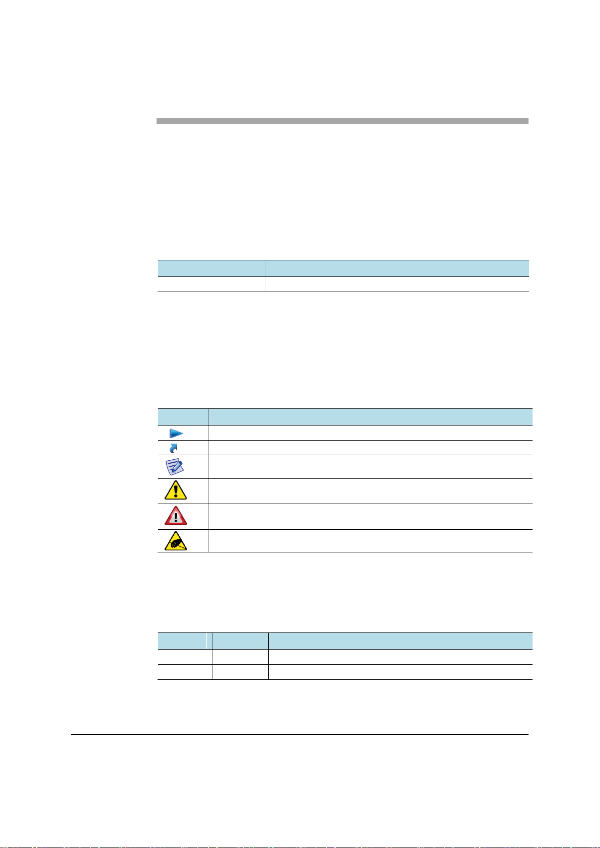
Symbol
Description
Indicates a task.
Indicates a shortcut or an alternative method.
Provides additional information.
Provides information or instructions that you should follow to avoid service
failure or damage to equipment.
Provides information or instructions that you should follow to avoid personal
injury or fatality.
Provides antistatic precautions that you should observe.
Version
Date
Description
1.0
10/31/2014
First Version
1.1
12/22/2014
Content Reduction
Preface
This manual describes how to install the Verizon 4G LTE Network Extender for
Enterprise and cable connection specifications.
Relevance
This manual applies to the following products/software.
Conventions in this Document
Samsung Networks product documentation uses the following conventions.
Symbols
Revision History
The following table lists all versions of this document.
Verizon 4G LTE Network Extender for Enterprise Installation Manual v1.0 vi
©Samsung
Page 7
Preface
Section
Title
Description
Chapter 1
Installing the System
Describes the procedures required to
perform the installation.
Chapter 2
Connecting the Cables
Describes the procedures and checks
required to connect the system.
Appendix A
Before Installation
Describes the procedures and checks
required prior to installation.
Appendix B
Optional GPS Antenna
Installation
Describes the procedures required to
install a GPS antenna system.
Appendix C
Installing the Feeder Cable
Describes the specifications and
cautions required to install a feeder
cable.
Appendix D
Connector Assembly
Describes the procedures required to
assemble connectors.
Appendix E
Pressure Terminal Assembly
Describes the procedures required to
assemble a pressure terminal.
Appendix F
Standard Torque
Provides the standard torque values.
Appendix G
Acronyms
List of terms.
Organization of This Document
Related Documentation
Verizon 4G LTE Network Extender for Enterprise Quick Start Guide
Verizon 4G LTE Network Extender for Enterprise Product, Safety and
Warranty
Verizon 4G LTE Network Extender for Enterprise User Guide
Personal and Product Safety
This product safety information includes U.S. directives that you must follow.
All applicable OSHA regulations and standards shall be followed.
The installation, maintenance, or removal of telecommunications equipment
requires qualified, experienced personnel. Samsung installation instructions are
written for such installation personnel.
Site Safety
Site construction shall be design-approved and certified by engineers who have
valid and up-to-date P.E. license approval with the National Society of
Professional Engineers.
Verizon 4G LTE Network Extender for Enterprise Installation Manual v1.0 vii
©Samsung
Page 8

Materials
Electrical
Preface
Workers shall evaluate site safety as per all applicable safety ordinances and
requirements including, but not limited to OSHA, NFPA 70, and applicable
building code requirements prior to, during, and after completion. Workers shall
not conduct product work until and unless the site is in full safety compliance with
associated regulatory requirements.
Workers shall use only approved materials that comply with applicable safety and
environmental requirements. All materials shall be deployed in accordance with all
applicable safety requirements, and according to manufacturer instruction.
Workers shall not install any materials that are intrinsically unsafe, or have
shipping, handling, or installation instructions that are intrinsically unsafe.
This product contains hazardous energy levels as defined by UL 60950. Care must
be taken as injury to personnel or damage to the equipment could result from
mistakes. Maintenance should only be carried out by approved workers who have
adequate training and understanding, and are familiar with the required procedures
and instructions.
In addition to all applicable safety requirements, workers shall abide by the latest
edition of NFPA 70 national electrical code. Certified and licensed Electricians
and Power Limited Technicians shall perform electrical work as required by
applicable regulatory requirements.
All structural materials shall be grounded, and all input and outputs shall have
built-in isolation from the network as per NFPA 70 standards and client-approved
standards. All connectivity and input and output hardware ports that connect to
external power sources shall be designed and installed to meet national safety and
regulatory requirements.
Shipping, Transport, and Manual Handling
Worker shall assure they understand and abide by all associated regulatory and
standards instruction applicable to shipping, transport and handling of product,
including but not limited to OSHA and all associated Samsung documentation for
product shipping, transport, and manual handling requirements.
Worker shall assure adequate and approved shipping, transport, and handling
procedures are utilized to maintain safety.
Installation
Installation shall be carried out by trained and competent workers observing all
applicable safety rules and regulations at all times.
Workers shall read, and understand the latest published installation documentation,
and make sure all required workers, tools, and materials are approved and present
prior to beginning any defined work task.
Verizon 4G LTE Network Extender for Enterprise Installation Manual v1.0 viii
©Samsung
Page 9

Preface
Workers shall also abide by the latest published installation documentation for
general work procedures and guidance materials.
All relevant safety measures must be taken to ensure that equipment is not
connected to live power and transmission sources during installation. Equipment
must be correctly installed in order to meet the relevant safety standards and
approval conditions.
Maintenance
Maintenance shall be carried out by trained and competent workers while
observing all applicable safety rules and regulations at all times. Equipment covers
shall not be removed while live power and/or transmission is connected unless
specifically directed by a Samsung published work instruction and as determined
safe by all associated safety rules and regulations.
Environment
The product must be operated in an environment within the specified relative
humidity and ambient temperature ranges.
Keep all liquids away from the equipment, as accidental spillage can cause severe
damage.
Verizon 4G LTE Network Extender for Enterprise Installation Manual v1.0 ix
©Samsung
Page 10
Preface
Grounding
To comply with ANSI/NFPA70 and UL 60950, equipment must be connected to a
safety grounding point via a permanent connection. Grounding points are located
on the product for this purpose. Always connect the ground cable as per the latest
published instructions before fitting other cables. The product must remain
grounded continuously unless all system and power connections are removed.
If equipment is grounded through a cabinet or rack, make sure it is done so
properly according to the latest published installation instructions.
.
AC System
Single pole /neutral fusing
Disconnect AC power, before servicing.
RF Cable Installation
Circuit Breaker
Installation shall be in accordance with the applicable parts of Chapter 8 of
ANSI/NFPA 70.
Branch circuit protection
The power system must be equipped with external branch circuit protection that
complies with NEC requirement and have a rating maximum of 20A.
(Use UL-listed circuit breaker.)
Verizon 4G LTE Network Extender for Enterprise Installation Manual v1.0 x
©Samsung
Page 11
Chapter 1 Installing the
System
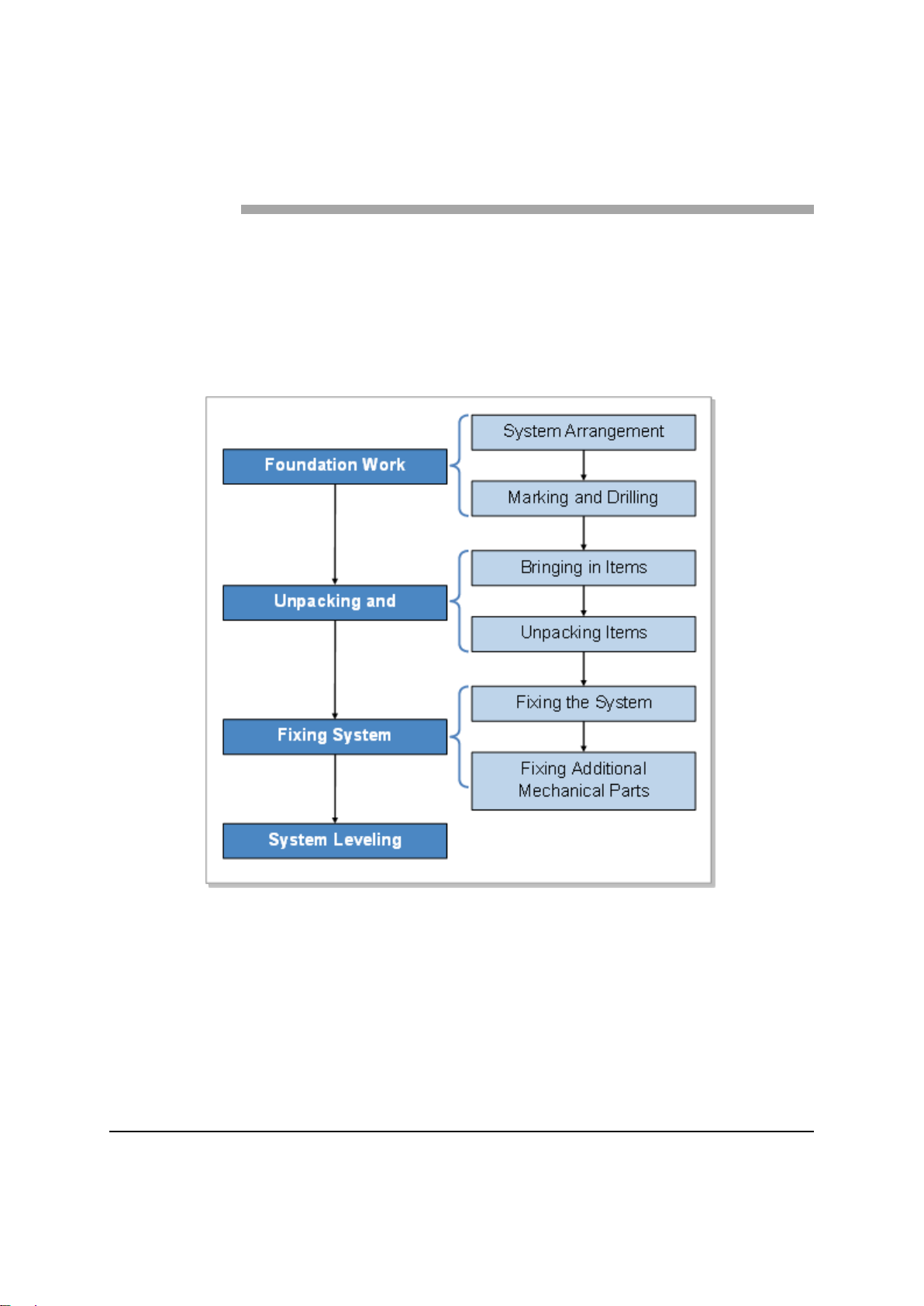
Installing the 4G LTE Network Extender
The procedure to install the 4G LTE Network Extender is shown in the following
figure.
Figure 1. Procedure to Install the System
Verizon 4G LTE Network Extender for Enterprise Installation Manual v1.0 11
©Samsung
Page 12
Appendix A Before Installation
Category
Recommended Distance
Top
19.69 in. (500 mm) or more
Front
19.69 in. (500 mm) or more
Sides
7.87 in. (200 mm) or more
Foundation Work
System Arrangement
A minimum distance must be secured around the 4G LTE Network Extender, in
each direction for installation and maintenance.
Table 1. Recommended Distances for 4G LTE Network Extender Installation
Verizon 4G LTE Network Extender for Enterprise Installation Manual v1.0 12
©Samsung
Page 13
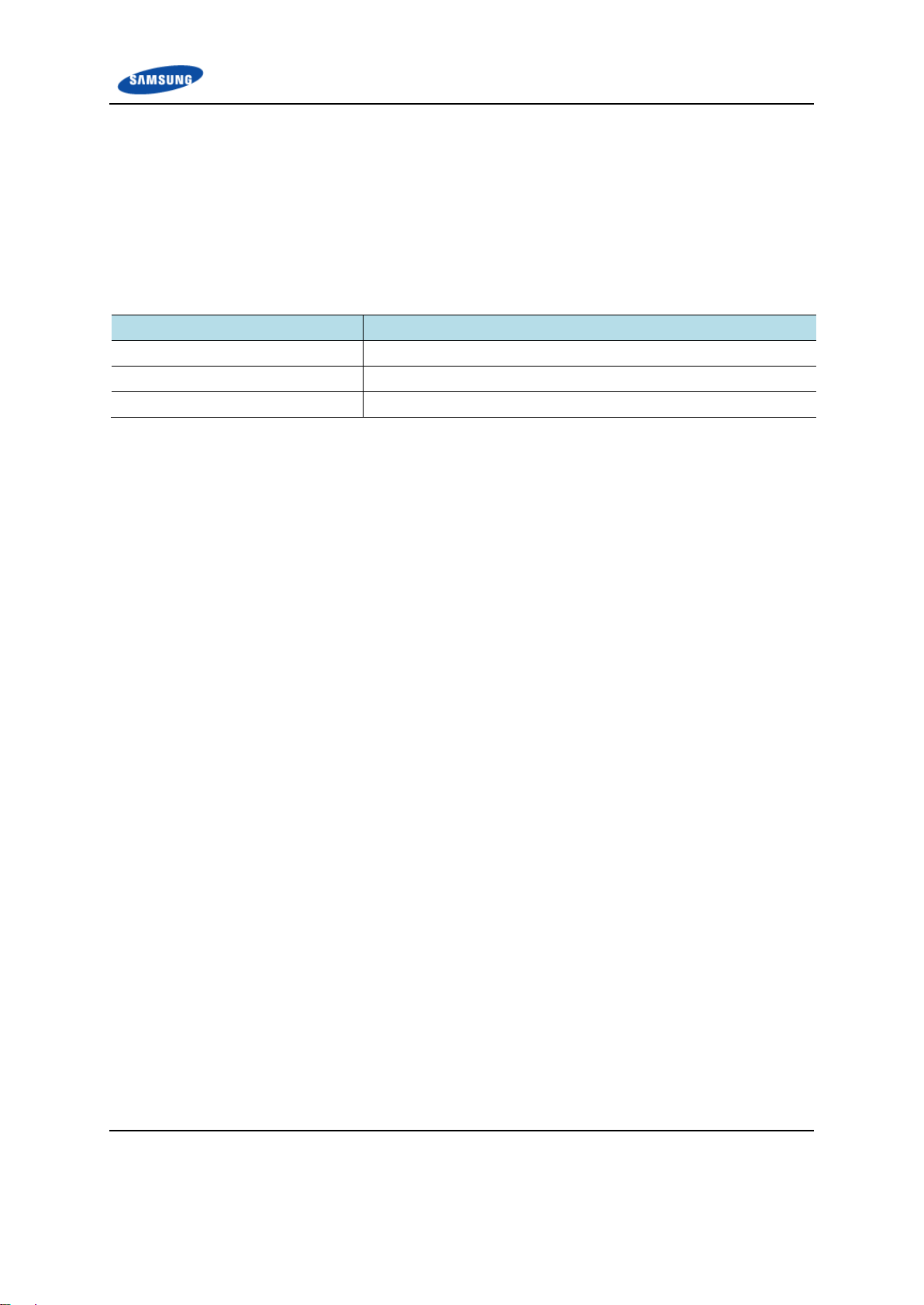
Appendix A Before Installation
≒ 11.5(292.5)
3(75.2)
2(50.2)
10.6(269.3)
≒ 4.9(125.4)
0.89(22.5)
90
90
4.6(116)
5.8(147)
5.8(147)
≒ 16.2(410.6)
[Top View]
[Left View]
90
Unit: in (mm)
Figure 2. 4G LTE Network Extender Dimensions
Verizon 4G LTE Network Extender for Enterprise Installation Manual v1.0 13
©Samsung
Page 14
Appendix A Before Installation
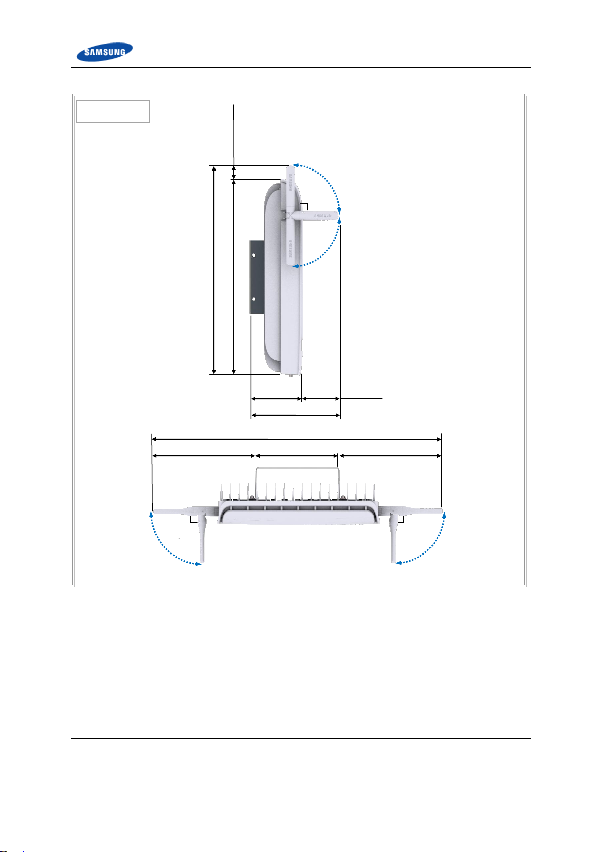
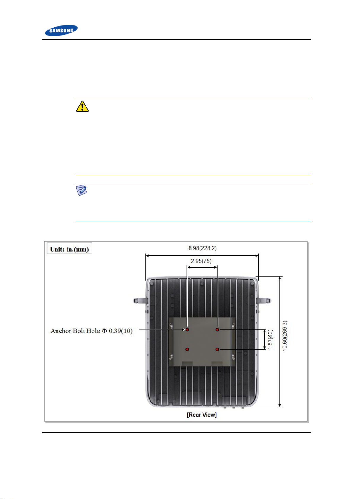
Marking and Drilling
Marking
Before placing the system, mark the position where the system will be installed
and also the positions where anchor bolts will be fixed using an ink line or a pen.
Check Marking (Horizontal/Vertical) When Mounting the System on Wall
If you do the drilling or anchoring on a wall, ensure the positions are marked as
horizontal or vertical, as only a limited range of tuning is allowed for leveling after
the system is mounted.
To mount the system on a wall, perform the leveling test by referring to the
System Leveling section to check that positions are marked to be horizontal or
vertical before drilling. If the result shows that they are not horizontal or vertical,
modify the marking positions.
Marking Using the System
When the device position is determined, place the mounting bracket on the surface
and then mark the positions where anchor bolts will be fixed using a pen. This will
reduce marking error.
Figure 3. System Marking - Wall Type
Verizon 4G LTE Network Extender for Enterprise Installation Manual v1.0 14
©Samsung
Page 15
Appendix A Before Installation
Category
Anchor Bolt
Drill Bits
Hole Depth
Wall Type
M4
0.24 in. (6 mm)
1.18 in. (30 mm)
Drilling
When marking is completed, drill holes for anchor bolts.
Table 2. Anchor Bolt Drill Bits and Hole Depth
Verizon 4G LTE Network Extender for Enterprise Installation Manual v1.0 15
©Samsung
Page 16

Appendix A Before Installation
Unpacking and Transporting
This section describes the work to unpack cabinets and other components, and
transport them to the place to be installed.
Bringing in Items
Bring in items, taking care of the following:
Use a lift or cart to prevent accidents. However, if multiple systems must be
carried by people, make sure that there are enough people to carry the system
safely.
Before moving the systems, check the storage place and remove obstacles in
advance.
While moving the systems, avoid potential damage caused by physical shock,
dust, moisture, or static electricity.
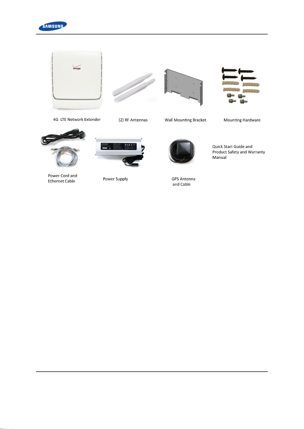
Unpacking Items
The procedure to unpack items is as follows:
1 The items should be packed until they reach the installation place.
2 The items are classified in accordance with each job specification and stored in
a place that does not interfere with the working area.
3 Unpacked systems should be installed immediately. If not installed
immediately, the systems should be stored in the installation place temporarily.
4 Unpack the inner packaging after each system is placed on its installation
location.
5 Dispose of packing waste it in accordance with local laws.
Verizon 4G LTE Network Extender for Enterprise Installation Manual v1.0 16
©Samsung
Page 17
Appendix A Before Installation
Figure 4. Package Contents
Verizon 4G LTE Network Extender for Enterprise Installation Manual v1.0 17
©Samsung
Page 18
Appendix A Before Installation
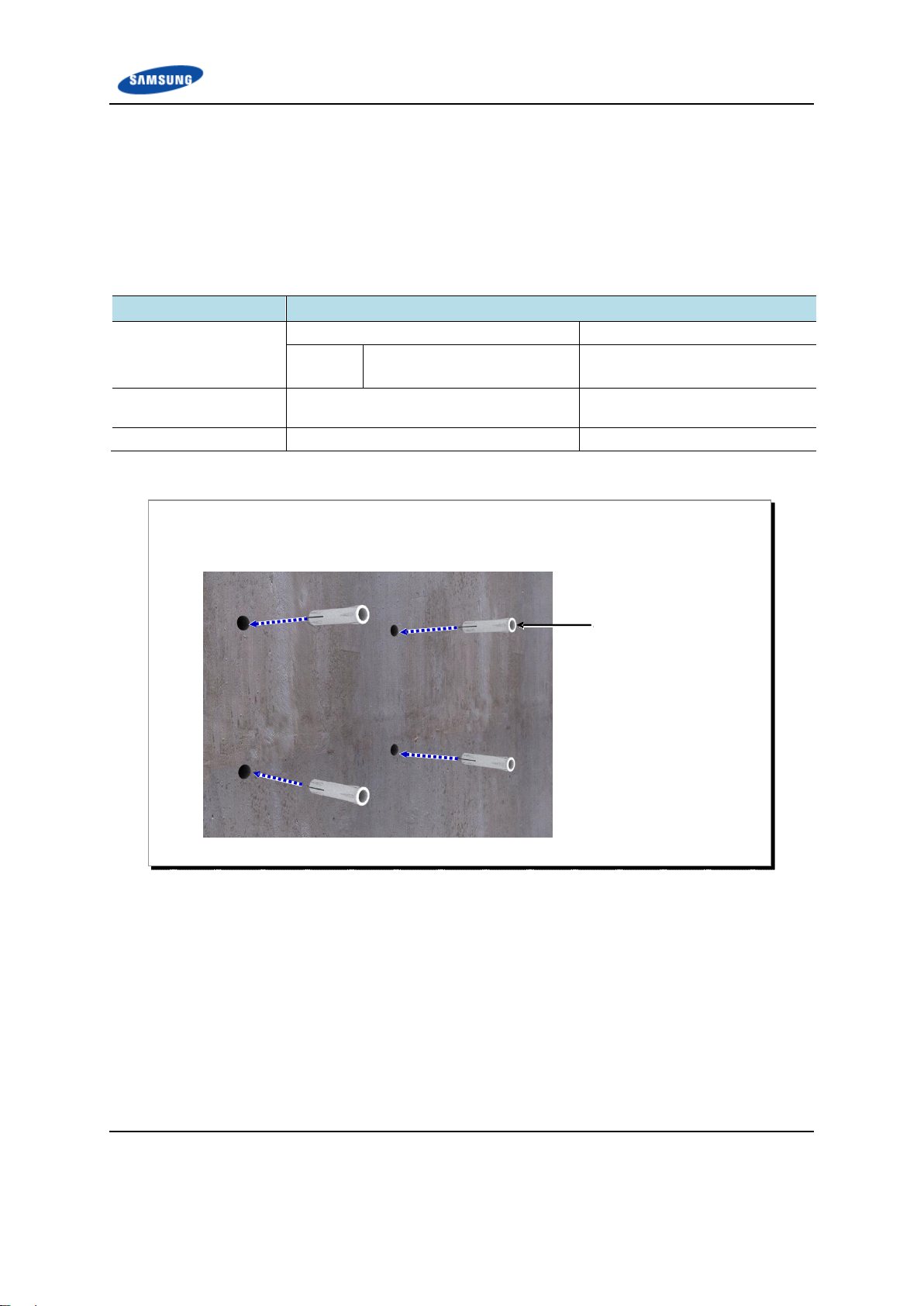
Classification
Description
Parts
Wall Mounting Bracket
1 EA
Fastener
M4 x 20L TH Tapping Screw
M6 x 30L Plastic Anchor
4 EA
4 EA
Recommended Torque
Value [ft.lb. (kgf.cm)]
M4 Tapping Screw
0.69~1.03 (9.5~14.3)
Working Tools
Drill, Hammer, Torque Wrench, Level
Working Tools
1 Fix the M6 plastic anchors to the holes marked and drilled on the wall.
Plastic
Anchor
Fixing the 4G LTE Network Extender
Fixing the Wall Mounting Bracket
The procedure for fixing the wall mounting bracket is as follows.
Table 3. Fixing the Wall Mounting Bracket - Parts and Tools
Figure 5. Fixing the Wall Mounting Bracket (1)
Verizon 4G LTE Network Extender for Enterprise Installation Manual v1.0 18
©Samsung
Page 19
Appendix A Before Installation
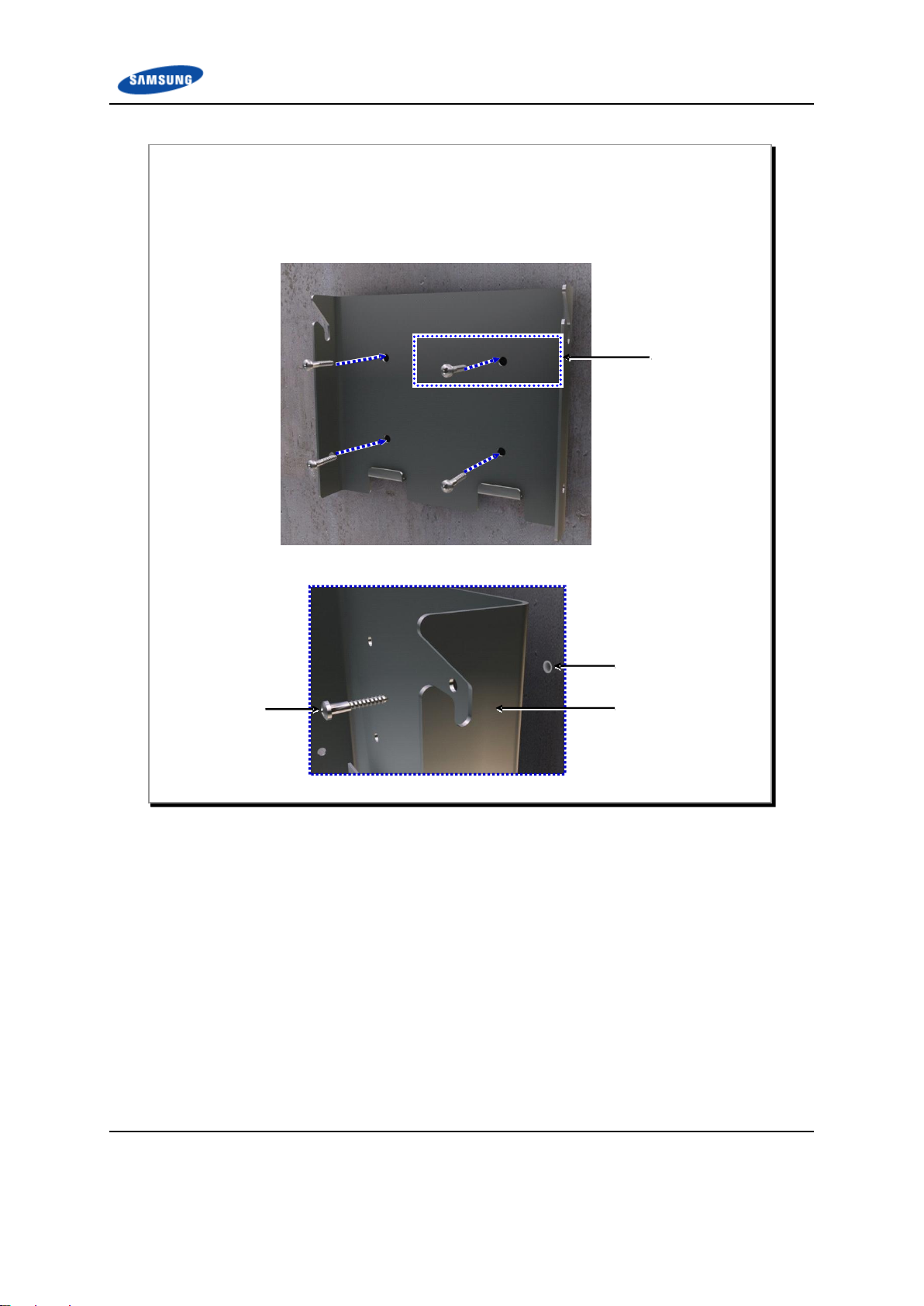
‘A’
Detail
‘A’
Tapping
Screw
Wall Mounting
Bracket
Plastic Anchor
2 Place the wall mounting bracket along with the fixed M6 plastic anchors.
3 Securely fix the wall mounting bracket using four tapping screws in the holes.
Figure 6. Fixing the Wall Mounting Bracket (2)
Verizon 4G LTE Network Extender for Enterprise Installation Manual v1.0 19
©Samsung
Page 20
Appendix A Before Installation
Classification
Description
Parts
Unit Mounting Bracket
1 EA
Fastener
M3 × 8L SEMS
M4 × 10L SEMS
4 EA
4 EA
Bakelite(5T)
2 EA
Recommended Torque
Value [ft.lb. (kgf.cm)]
M3 SEMS
M4 SEMS
0.29~0.44(4.08~6.12)
0.69~1.03(9.52~14.28)
Working Tools
Torque Driver
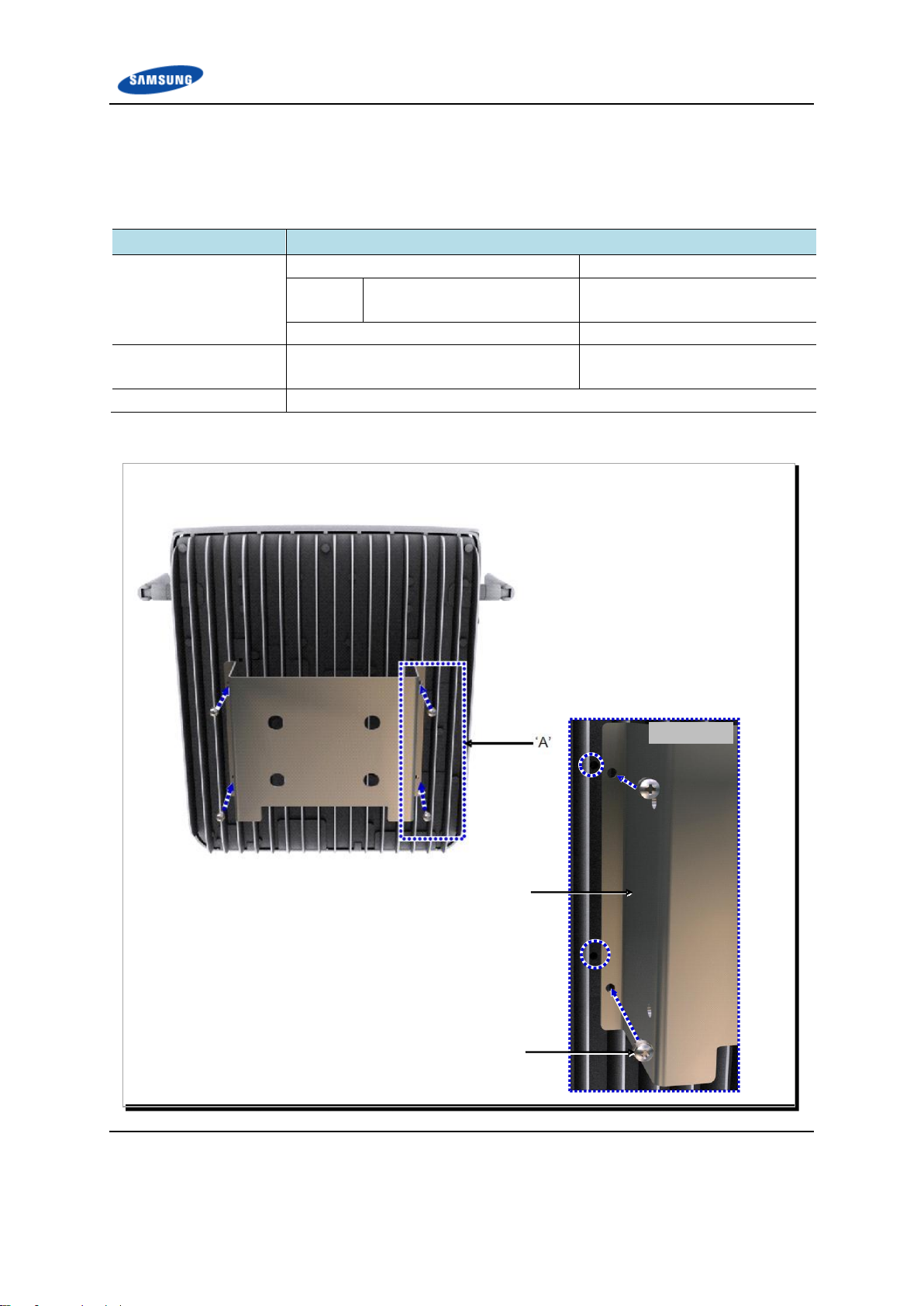
Detail
‘A’
1 Fix the unit mounting bracket to the four holes on the rear side of the 4G LTE Network Extender if not
preassembled.
M3 SEMS
Unit Mounting
Bracket
Fixing the 4G LTE Network Extender
The procedure for fixing the 4G LTE Network Extender is as follows.
Table 4. Fixing the 4G LTE Network Extender - Parts and Tools
Figure 7. Fixing the 4G LTE Network Extender (1)
Verizon 4G LTE Network Extender for Enterprise Installation Manual v1.0 20
©Samsung
Page 21
Appendix A Before Installation
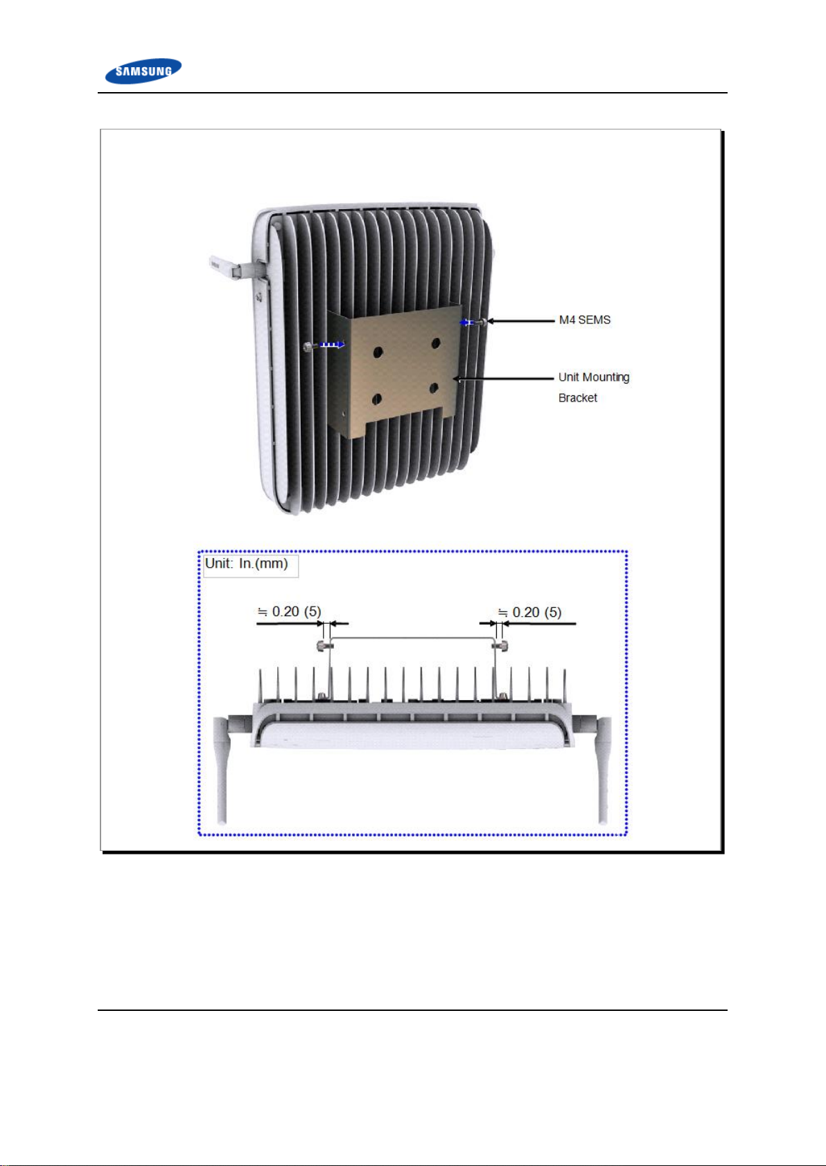
2 Fix the M4 SEMS temporarily to the fixing holes at the top left and right sides of the unit mounting
bracket, leaving about 0.20 in. (5 mm) clearance between the M4 SEMS and the unit mounting bracket.
Figure 8. Fixing the 4G LTE Network Extender (2)
Verizon 4G LTE Network Extender for Enterprise Installation Manual v1.0 21
©Samsung
Page 22
Appendix A Before Installation
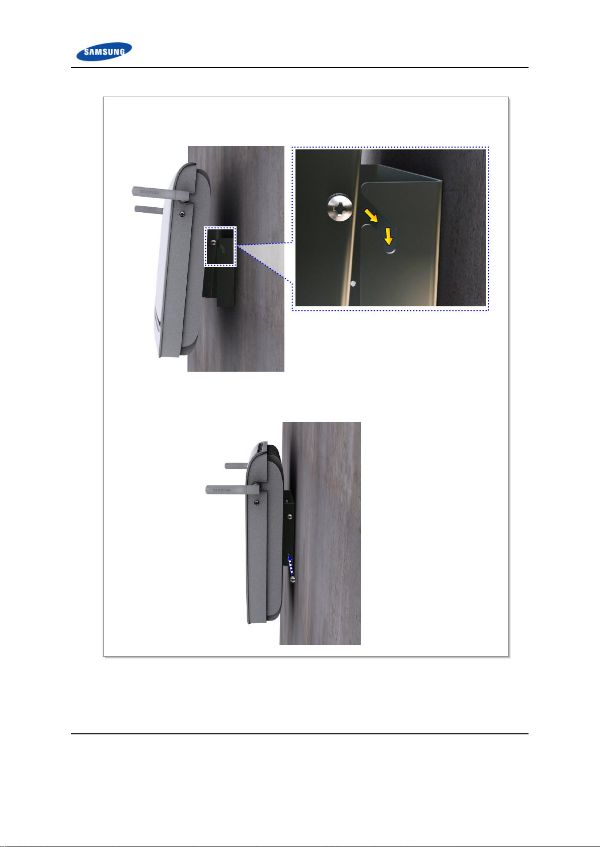
3 Hang the SEMS, fixed on the top left and right sides of the unit mounting bracket, over the
top groove of the wall mounting bracket.
4 Fix the fasteners to the rest of the fixing holes.
5 Firmly fix the fasteners that were temporarily fixed to the top left and right sides of the 4G
LTE Network Extender.
Figure 9. Fixing the 4G LTE Network Extender (3)
Verizon 4G LTE Network Extender for Enterprise Installation Manual v1.0 22
©Samsung
Page 23
Appendix A Before Installation
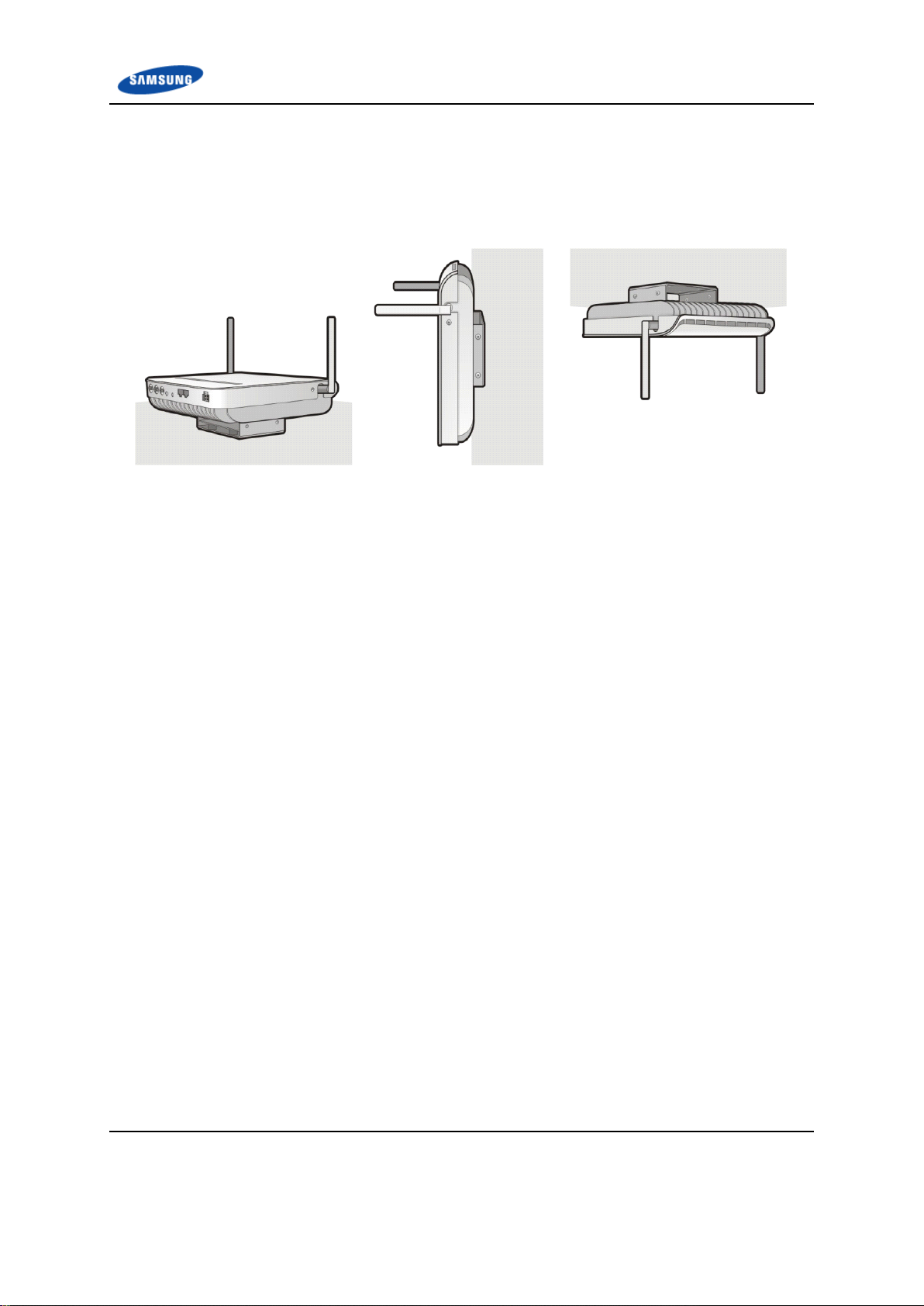
[Floor]
[Wall]
[Ceiling]
Fixing the 4G LTE Network Extender on the Ceiling or Flat Surface
The procedures for fixing the system on the ceiling or a flat surface are the same as
fixing the system on the wall.
Figure 10. Fixing 4G LTE Network Extender on the Ceiling or Flat Surface
Verizon 4G LTE Network Extender for Enterprise Installation Manual v1.0 23
©Samsung
Page 24
Appendix A Before Installation
Grounding
Power Cabling
GPS Arrestor Grounding
External Interface
Connection
Backhaul Cable
GPS Cable Connection
Chapter 2 Connecting the
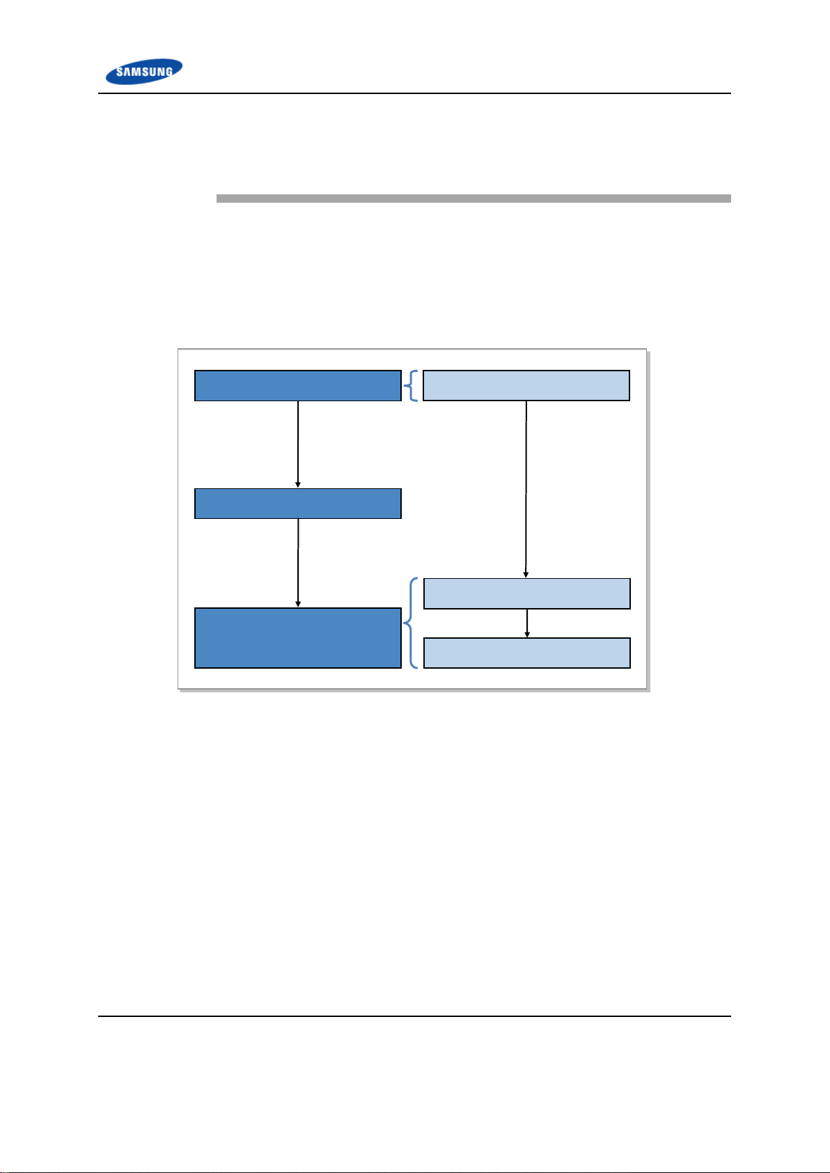
Workflow for Cabling
The cable workflow for the system is as follows.
Figure 11. Workflow for System Cabling
Cables
Verizon 4G LTE Network Extender for Enterprise Installation Manual v1.0 24
©Samsung
Page 25
Appendix A Before Installation
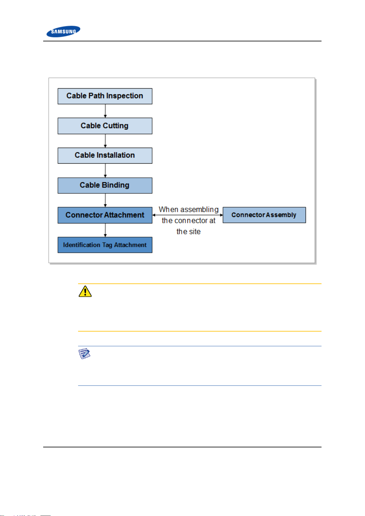
The detailed procedure for cabling is as follows.
Figure 12. Detailed Cabling Procedure
Considerations when Cutting the Cable after Installation
When cutting the cable after installation, make sure that the connector is
disconnected. Installation of the cable with the connector connected to the system
may cause contact failure or damage to the connector assembled to the system and
the cable due to cable tension or the operator’s mistakes.
Cabling Workflow
The sequence of cable cutting and installation of the cable workflow can be
changed depending on the field situation such as ‘cutting after installing’ or
‘installing after cutting’.
Verizon 4G LTE Network Extender for Enterprise Installation Manual v1.0 25
©Samsung
Page 26
Appendix A Before Installation
No
Type
Allowed Cable Bend Radius
Remark
1
F-GV/F-CV/FR-8
Eight times of the cable
external diameter
0.6/1 KV Cable
2
Optic Cable
20 times of the cable
external diameter
-
Cable Path Inspection
Follow these guidelines when inspecting the cabling path:
A minimum cable length must be selected, provided that it does not affect the
cable installation and maintenance.
The cable must be placed in a location where it will not be damaged by
external factors (such as power line, flooding, and footpaths).
In areas where the cable may be damaged by external factors (such as cable
tray, ducts, and flexible pipe), ensure that measures are taken to prevent
damage to the cable.
Cable Cutting
Measure the exact distance, carefully checking the route, and cut the cable using a
cutting tool.
Follow these guidelines when cutting the cable:
Cut the cable to the length determined in the Cable Path Inspection step.
Use a dedicated cable cutting tool.
Cut the cable at right angles.
Be careful to keep the cable away from any moisture, iron, lead, dust or other
foreign material when cutting.
Remove any foreign material attached to the cable using solvent and a brush.
Cable Installation
Cable installation involves running the cable along the cabling path to the target
connector of the system or an auxiliary device after the cable path inspection and
cable cutting have been completed.
Follow these guidelines when installing a cable:
Be careful not to damage the cable.
Always use the maximum curvature radius possible, and make sure that the
minimum curvature radius specification is complied with.
If the cable needs to be protected, use a PVC channel, spiral sleeve, flexible
pipe, or cable tray.
Table 5. Recommended Minimum Allowed Cable Bend Radius
Verizon 4G LTE Network Extender for Enterprise Installation Manual v1.0 26
©Samsung
Page 27

Appendix A Before Installation
No
Type
Allowed Cable Bend Radius
Remark
3
UTP/FTP/S-FTP Cable
Four times of the cable
external diameter
PVC/LSZH,
4 Pair
4
1/2 in. Feeder Line(Indoor)
1.26 in. (32 mm)
RFS, LS
5
1/2 in. Feeder Line(Outdoor)
4.92 in. (125 mm)
RFS, LS
6
7/8 in. Feeder Line(Outdoor)
9.84 in. (250 mm)
RFS, LS
7
1-1/4 in. Feeder
Line(Outdoor)
14.96 in. (380 mm)
RFS, LS
8
1-5/8 in. Feeder
Line(Outdoor)
19.69 in. (500 mm)
RFS, LS
9
LMR-400
1 in. (25.4 mm)
Installation
4 in. (101.6 mm)
Repeated
10
RG-316D
0.59 in. (15 mm)
-
※ If the allowed cable bend radius is specified by the manufacturer, comply with the bend radius specified.
Cable Binding
Cable binding involves fixing and arranging an installed cable using binding
thread, cable ties, binding wire, and ram clamps.
Follow these guidelines when binding a cable:
Be careful not to damage the cable during binding.
Use appropriate cable binding tools according to the target location (indoor or
outdoor) and the use of the cable (such as power supply cable, optical cable, or
feeder line).
Do not let the cutting section of a cable tie, binding line, and so on be exposed
to the outside. This may cause damage to cables or personal injury. Make sure
that the cutting sections of the cables are not exposed to the outside.
Trim the cable binding cord at a 50 mm distance from its knob and insert it
into the knot so that the knot does not loosen.
Verizon 4G LTE Network Extender for Enterprise Installation Manual v1.0 27
©Samsung
Page 28

Appendix A Before Installation
Connector Attachment
Connector attachment involves assembling a connector to an installed cable or to a
device on the site.
Follow these guidelines when attaching a connector:
Make sure you are fully aware of the connector assembly method before
assembling a connector. Assemble the connector in accordance with its pin
map.
Each connector has a hook to prevent its core positions from being changed.
Check the corresponding grooves before connecting a connector to another
connector.
Use a heat shrink tube at a connector connection for cables that are installed
outdoors, such as feeder lines, to prevent water leakage and corrosion from
occurring at the part exposed to the outside.
Connect each cable of the connector assembly in a straight line.
Be careful when connecting a cable so that contact failure does not occur at a
connector connection due to tension.
Identification Tag Attachment
Identification tag attachment involves attaching a marker cable tie, nameplate, and
label to both ends of a cable (connections to a connector) to identify its use and
cabling path.
Marker Cable Tie
On the marker cable tie, a label can be attached. The
appearance and specification may differ depending
on the type and manufacturer.
Follow these guidelines when attaching an identification tag:
When installing a cable outdoors, use relief engraving and coated labels to
prevent the markings from being erased.
Since the form and attachment method for identification tags are different for
each provider, consult with the provider before attaching them.
Connecting Ground Cable
When connecting the cables, always connect the ground cable first. If a person
comes in contact the equipment, connects a cable, or performs maintenance
without connecting the ground cable, the system can be damaged or someone may
be injured due to static electricity and/or short circuit.
Verizon 4G LTE Network Extender for Enterprise Installation Manual v1.0 28
©Samsung
Page 29

Appendix A Before Installation
Finishing the System I/O Ports and Cable Inlet
To prevent foreign substances, outdoor air and moisture from entering the system
I/O ports (power, external interface, and so on) and cable inlet, finish it as follows:
- Unused inlets
Use finishing materials including dust cap and rubber packing.
- Cable-installed inlet
After cable installation, block any space in the inlet with dust covers.
Cable Installation Checklist
When installing, take care not to overlap or tangle the cables; also, consider future
expansion. Install the DC power cable and data transmission cable away from the
AC power cable to prevent electromagnetic induction.
Verizon 4G LTE Network Extender for Enterprise Installation Manual v1.0 29
©Samsung
Page 30

Appendix A Before Installation
Cabling
The cabling diagram of the 4G LTE Network Extender is as follows.
Figure 13. Cabling Diagram
Verizon 4G LTE Network Extender for Enterprise Installation Manual v1.0 30
©Samsung
Page 31

Appendix A Before Installation
From
To
Cable
MGB
Optional GPS Arrestor
1 GPS Arrestor Ground Cable
AWG8, F-GV 6 mm2 × 1C
AC Distributor
AC/DC Adaptor
2 Power Cable-1
Power Cable Assembly-1
AC/DC Adaptor
4G LTE Network Extender
3 Power Cable-2
Power Cable Assembly-2
4G LTE Network
Extender
Switch or Router
4 Backhaul Cable
S-FTP Cat.5e or Cat.6, 4 Pair #24
328 ft.(100m) or less
GPS Antenna
5 GPS Cable-1
RG-316D(9.8 ft./3 m or less)
GPS Arrestor
Optional GPS Antenna
6 GPS Cable-2
LMR-400 [Extension cable from RG316D to GPS Arrestor when the length
of GPS cable-1 is over 9.8 ft.(3m)]
Table 6. 4G LTE Network Extender Connection Cable
Verizon 4G LTE Network Extender for Enterprise Installation Manual v1.0 31
©Samsung
Page 32

Appendix A Before Installation
GPS Requirements
Installation Requirements for the GPS Antenna
The GPS antenna must be installed in a location where it has the maximum
amount of open sky. The ideal position is one where there are no obstacles that
interfere with the antenna within 10 degrees or more of the horizon (the elevation
angle). This allows the GPS receiver to select the best combination or distribution
of GPS satellites that gives optimal performance.
Figure 14. Elevation Mask and Satellites
For good signal strength, you do not have to place the GPS antenna on a high pole
or building, which is often required for RF and microwaves reception.
Any place where there are no obstacles blocking the GPS antenna from the sky
and where it is protected from the outdoor elements is suitable. In this case, you
can even install it on the floor.
However, you can prevent the GPS antenna from malfunctioning by installing it in
a place where it does not receive reflected satellite signals. As multi-path
interference greatly affects the accuracy of the GPS receiver, it is better to
minimize reflected satellite signals entering through the top of the GPS antenna.
Verizon 4G LTE Network Extender for Enterprise Installation Manual v1.0 32
©Samsung
Page 33

Appendix A Before Installation
Therefore, the GPS antenna installation location must meet the following three
guidelines:
1 A location that can avoid the effects of many obstacles and buildings that
interfere with GPS reception and cause multi-path interference.
2 A location that can avoid RF signal interference. Keep clear from other RF
antennas as well as steel-framed structures or microwave signals.
3 In outdoor applications, a location as low as possible and within a coverage
area of a lightning rod to avoid damage from lightning.
Considerations for Elevation Mask
Considering the elevation mask, make the GPS antenna take the signals received at
a valid elevation angle only.
Countermeasures for External Interference and Multi-Path Influences
If a GPS antenna is influenced by external interference signals or multi-path
interference at a certain place, it is best to reinstall the antenna at another place.
GPS Antenna Sharing
To ensure the GPS receiver works properly, it is recommended that you install one
GPS antenna per GPS receiver. It is also recommended that you use a GPSspecific splitter only if absolutely necessary.
Installing the GPS Antenna
The signals from a GPS satellite have a very low level (-130 dBm). Therefore, the
GPS receiving antenna should be installed in a place where it can receive signals
in direct line of sight, limiting the number of walls and floors as possible.
To receive as many satellite signals as possible, it is important to ensure there is
maximum open sky. The visual field angle must be 360 degrees, and there must
be 160 degrees or more above the horizon. If there are too many obstacles within
the horizon, it decreases the performance and functionality of the GPS receiver.
The GPS satellites are distributed so that eight of them can always be tracked from
any one place across the world, as long as there are no obstacles in the horizon.
For the GPS receiver to operate according to our needs, there must be three GPS
satellites with a healthy status for first fix (that is, there is no obstacle directly
between it and the GPS antenna). If the position hold operation has been
completed, the GPS receiver can perform its operations suitably if at least one
satellite can be tracked continually.
Verizon 4G LTE Network Extender for Enterprise Installation Manual v1.0 33
©Samsung
Page 34

Appendix A Before Installation
Classification
Description
Cable
AC Distribution~AC/DC Adaptor
Cable
Connector
AC/DC Adaptor~4G LTE Network
Extender Power Input Terminal
Power Cable Assembly-1 (120/240 V AC)
4G LTE Network Extender
Power Cable Assembly-2 (12 V DC)
Connector
AC/DC Adaptor
Tyco 4P/1-770968-1. Equivalent
Power Cabling
The power supply is configured as follows.
Figure 15. Power Equipment Diagram
Figure 16. AC/DC Adaptor
Table 7. Power Cable Connection
Adaptor Installation Environment
Because the adaptor is not waterproof, you should consider the installation
environment. The adaptor can be damaged due to electrical short-circuit from
water.
The adaptor must be installed in an open space for proper heat dissipation.
Verizon 4G LTE Network Extender for Enterprise Installation Manual v1.0 34
©Samsung
Page 35

Appendix A Before Installation
Spacing between AC/DC Adaptor and 4G LTE Network Extender
The AC/DC adaptor’s power cable length for the 4G LTE Network Extender is
4.92 ft. (1.5 m). The AC/DC adaptor should be installed where the cable length
does not exceed 4.92 ft. (1.5 m) for installation and connection to the 4G LTE
Network Extender.
Proper Circuit Breaker
To ensure a stable power supply, a slow blow (low speed operation) type circuit
breaker must be installed in the power cable connecting the AC power supply (or
power distributor) to the 4G LTE Network Extender. (Circuit breaker’s capacity: 5
A). After installing the circuit breaker, attach a tag showing the connected
system’s name to the breaker to prevent misuse.
Shutdown the Power Supply
The isolation procedure to turn the system power off is as follows:
In order to shut down the power supply to the entire system, the main power
switch on the AC power distribution should be turned off.
If the system needs to be shielded from the main power supply for service
purposes, the switches on the relevant circuit breakers (for example, those on
the AC power distribution or applied to building installation) must be turned
off.
If the system needs to be operated independently, the following (power) isolation
may be provided by unplugging the power supply cord or main plug.
Verizon 4G LTE Network Extender for Enterprise Installation Manual v1.0 35
©Samsung
Page 36

Appendix A Before Installation
Power Connector
Power Port
‘
Power Cable
Power Cable Assembly-2
D
e
t
a
i
l
‘
A
’
AC/DC
Adaptor
[AC Distribution]
Power Cable Assembly-1
[4G LTE NE]
1 Install and connect the power cable assembly-1 from the AC distributor to the AC/DC
adaptor.
2 Install the power cable assembly-2 of the AC/DC adaptor to the power input port of the 4G
LTE Network Extender. Then, connect the connector to the 4G LTE NE power input port.
Figure 17. Power Cable Connection
Verizon 4G LTE Network Extender for Enterprise Installation Manual v1.0 36
©Samsung
Page 37

Appendix A Before Installation
Classification
Description
Installation Section
Switch or Router~4G LTE NE Backhaul Port
Cable
S-FTP Cat.5e or Cat.6, 4Pair #24, 328.1 ft.(100 m) or less
Connector
Switch or Router
RJ-45
4G LTE Network Extender
Pin No.
10 Base-T/100 Base-TX
1000 Base-T
Color
Pair No.
1
Output signal positive
BI Data 0 positive
Orange/White
2
2
Output signal negative
BI Data 0 negative
Orange
2
3
Input signal positive
BI Data 1 positive
Green/White
3
4 - BI Data 2 positive
Blue
1
5 - BI Data 2 negative
Blue/White
1
6
Input signal negative
BI Data 1 negative
Green
3
7 - BI Data 3 positive
Brown/White
4
8 - BI Data 3 negative
Brown
4
External Interface Connection
Backhaul Cable Connection
Follow the steps below to connect the backhaul cable.
Table 8. Backhaul Cable Pin Map
Check when Assembling Cable Connector
The table above is based on the connectors on the system side, so it is necessary to
check the pin connection positions when connecting to the connectors on the cable
side.
Assembling the RJ-45 Connector
To see how to assemble an RJ-45 connector to a cable, refer to Appendix C,
Connector Assembly.
Verizon 4G LTE Network Extender for Enterprise Installation Manual v1.0 37
©Samsung
Page 38

Appendix A Before Installation
1 Install the backhaul cable from the switch (or router) to the B/H port of the 4G LTE Network
Extender.
2 Assemble the RJ-45 connectors and connector caps at both ends of the installed backhaul
cable.
3 Connect the assembled connectors to the B/H port of the 4G LTE Network Extender and
switch (or router).
‘
[4G LTE Network
Extender]
[Switch or Router]
Backhaul Cable
D
RJ-45 Connector
B/H (Backhaul) Port
Backhaul Cable
Figure 18. Backhaul Cable Connection
Verizon 4G LTE Network Extender for Enterprise Installation Manual v1.0 38
©Samsung
Page 39

Appendix A Before Installation
Classification
Description
Installation Section
4G LTE Network Extender to GPS Arrestor* to GPS Antenna
Cable
4G LTE Network Extender to
GPS Antenna
9.84 ft (3 m) or less
RG-316D
More than 9.84 ft (3 m)
RG-316D (9.84 ft or less)
+LMR-400
GPS Arrestor to GPS Antenna
(or Line Amplifier)
LMR-400
Connector
4G LTE Network Extender
SMA-Male
Connection part between RG316D and LMR-400*
RG-316D
N Type-Male
LMR-400
N Type-Female
GPS Arrestor*
N Type-Male
Line Amplifier*
N Type-Male
GPS Antenna
TNC-Male
Recommended
Torque Value
SMA-Male
0.18 ft.lb. (2.5 kgf.cm)
N Type-Male
1.45 ft.lb. (20 kgf.cm)
TNC-Male
0.65 ft.lb. (9 kgf.cm)
Working Tools
Cable Cutter, Wire Stripper, Nipper, Torque Wrench, Spanner, Knife, Soldering Iron,
Lead
* Optional Accessories
GPS Cable Connection
The following table lists the GPRS cable connector type and torque values.
Table 9. GPS Cable Connection
Installing GPS Line Amplifiers
The allowed length of a cable is limited according to the GPS cable configuration.
You must compensate for the signal loss by installing a line amplifier if the cable
exceeds the length allowed. Because the required number of line amplifiers and
installation method may vary depending on the extended length of the LMR-400
cable and line amplifier specifications, you must refer to the installation
instructions provided with the line amplifier.
In addition, you must install the line amplifier within 32.8 ft (10 m) from the GPS
antenna. The line amplifier is required when the total length of LMR-400 cable is
longer than 328.08 ft (100 m). See Appendix A for details.
Verizon 4G LTE Network Extender for Enterprise Installation Manual v1.0 39
©Samsung
Page 40

Appendix A Before Installation
Appendix A Before
Installation
Verizon 4G LTE Network Extender for Enterprise Installation Manual v1.0 40
©Samsung
Page 41

Appendix A Before Installation
10.60 (269.3)
Unit: in. (mm)
[Right View]
[Left View]
[Bottom
[Rear View]
[Top View]
2.17(55.2)
0.79(20)
8.98 (228.2)
[Front View]
11.2 (285.6)
System Configuration
4G LTE Network Extender Configuration
The 4G LTE Network Extender dimensions are as follows.
Figure 19. 4G LTE Network Extender Configuration
Verizon 4G LTE Network Extender for Enterprise Installation Manual v1.0 41
©Samsung
Page 42

Appendix A Before Installation
1PPS Verizon
Use only
RESET
LMT
RF
Antenna
RF
Antenna
GPS
10 M Verizon
use only
B/H (Backhaul)
PWR (Power)
[Bottom View]
4G LTE Network Extender External Interface
The 4G LTE Network Extender external interface structure is as follows.
Figure 20. 4G LTE Network Extender External Interface Structure
Verizon 4G LTE Network Extender for Enterprise Installation Manual v1.0 42
©Samsung
Page 43

Appendix A Before Installation
Item
Specification
Operating Frequency
(selective)
Band 4 (UL: 1710~1755MHz, DL:2110~2155MHz) or
Band 13 (UL:777~787MHz, DL: 746~756MHz)
Channel Bandwidth
5/10MHz
Capacity
1Carrier/Omni
Antenna Configuration
2Tx/2Rx
RF Output Power
250mW/Path (Total 500mW)
Active UE
42 Active UE (=RRC connected UE)
Backhaul Interface
100Base-TX/1000Base-T (RJ45)
Synchronization (selective)
AGPS or IEEE1588v2
Holdover
GPS 24 hours, IEEE1588v2 48 hours
Operational temperature
0 ~ 50°C
Humidity
8~95% (Non-condensing, not to exceed 30g/m3 absolute humidity)
EMC/Safety/Dust Rating
FCC Part 15 / UL 60950 / IP5X
Cooling
Convection cooling
O&M protocol
TR-069
Security
IPsec
Installation
Wall, Floor, Ceiling and 19 inch Rack mounting
Volume
Volume: 3. 39 Liters
Power Supply (selective)
AC 105 – 125 VAC @ 60 Hz (± 5% of the Input Voltage) with external
adaptor or High power PoE.
Power consumption
45W with AC adapter / 51W with High Power PoE
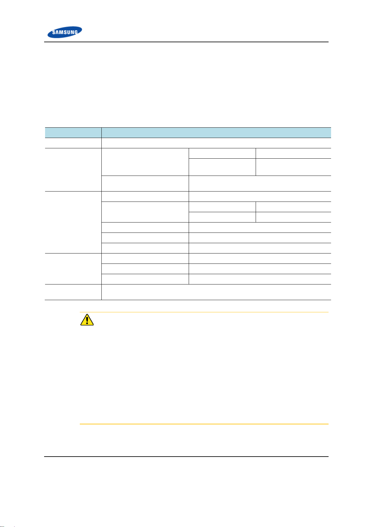
Specifications
Key Specifications
The key specifications of the 4G LTE Network Extender are as follows.
Table 10. Key Specifications
Verizon 4G LTE Network Extender for Enterprise Installation Manual v1.0 43
©Samsung
Page 44

Appendix A Before Installation
Item
Specification
4G LTE Network Extender
External AC adapter (100~254 V AC)
Power Consumption
POE
AC Adaptor
TYP
38W
34W
MAX
42W
38W
Item
Specification
Size (W×D×H) [in. (mm)]
8.98 (228.2) × 2.17 (55.2) × 10.60 (269.3)
Weight [lb (kg)]
5.29 (2.4kg)
Item
Specification
Received Signal from GPS
GPS L1 Signal
Accuracy/Stability
±0.05 ppm (frequency)
Cold Start (no AGPS)
-148dBm
Warm Start (w/ AGPS)
-152dBm
Tracking
-162dBm
Item
Specification
Clock Source
1588 Grand Master
Input Power
The power specifications of the 4G LTE Network Extender are as follows.
Table 11. Input Power
Table 12. Power Specifications
Dimensions and Weight
The dimensions and weight of the 4G LTE Network Extender are as follows.
Table 13. Dimensions and Weight
GPSR Specifications
The specifications of the 4G LTE Network Extender’s GPS receiver (GPSR) are as
follows.
Table 14. GPSR Specifications
IEEE1588v2 Specifications
The IEEE1588v2 specifications for the 4G LTE Network Extender are as follows.
Table 15. IEEE1588v2 Specifications
Verizon 4G LTE Network Extender for Enterprise Installation Manual v1.0 44
©Samsung
Page 45

Appendix A Before Installation
Item
Specification
Accuracy/Stability
±0.05 ppm (frequency)
Packet delay variation (PDV)
<125μs
Item
Specification
Temperature
0~50 °C (32~122 ℉)
Storage Temperature
-40~70 °C (-40~158 ℉)
Humidity
5~90 % RH
Storage Humidity
5~95 % (RH)
Altitude
60~1,800 m @ 50°C
1,800~4,000 m @ 40°C
Earthquake
Richter magnitude 7.0~8.3 (Zone 4, Telcordia GR-63 CORE)
Sound Pressure Level
45 dBA or below; 3.28 ft (1.0 m) distance from the product surface
Dust Rating
IEC60529, IP2X
EMC
FCC Part 15
Fire Test
UL 2043
Ambient Specifications
The ambient specifications for the 4G LTE Network Extender are as follows.
Table 16. Ambient Specifications
Verizon 4G LTE Network Extender for Enterprise Installation Manual v1.0 45
©Samsung
Page 46

Appendix A Before Installation
Cautions for Installation
Observe the following safety instructions when installing the 4G LTE Network
Extender.
Before Installing
Post warning signs in areas where high-voltage cables are installed.
Post ‘off limit’ signs in areas where accidents are most expected.
With guardrails or fences, block open areas such as connecting parts, roof, and
scaffold.
While Installing
The system power must be cut off before installing.
Power Switch Off
Make sure the power switch of the power supply is off when installing the system.
Installing the system with the power switch on may cause system damage or fatal
human injury when cables are not correctly connected.
Wearing Protective Gloves and Glasses
The workers should wear protective gloves and glasses because they can be
injured by the debris generated when drilling holes on walls or ceilings.
Do Not Wear Metal Things such as Watch, Ring, Etc.
Do not let an electric short circuit occur due to metal objects such as a watch or
ring.
Worker Injury
Avoid applying excessive force when installing the power cable in narrow areas.
Adjacent equipment and walls may cause accidental injury.
Do not Work by Yourself
A worker must not work alone during any key process.
Verizon 4G LTE Network Extender for Enterprise Installation Manual v1.0 46
©Samsung
Page 47

Appendix A Before Installation
Finishing the Cable Inlet
To prevent foreign substances, outdoor air and moisture from entering the cable
inlet (including the cable gland and conduit), finish it as follows:
- Unused inlet
Use the finishing materials including dust cap and rubber packing.
- Cable-installed inlet
After cable installation, block any space in the inlet with tape, compressed
sponge, rubber packing, and silicon.
After Installing
Cover the cable holes drilled on the floor with a solid cover.
Remove any debris produced during the work and clean up the installation site.
Cautions while Cleaning the Unit
Make sure that the worker does not damage the installed cables while cleaning the
unit.
Cautions while Cleaning Power Supply
While cleaning the power supply device, take caution that the device does not
come in contact with alien bodies that may cause power failure.
Cautions while System Operation
Because the system heat sink may become hot, avoid physical contact.
Pre-survey
To enable seamless construction, the installer and the service provider should
perform a preconstruction inspection to examine and analyze the following items:
Examination of the conformance and the economic efficiency of the place that
Status of external interfaces
Power capacity and wiring status
Possibility of system extension
Review if the place has the enough space for operation and maintenance.
the system is transported or installed
If there is a need for improvement or an issue, the installer and the service provider
must discuss measures to resolve any issue that arises.
Verizon 4G LTE Network Extender for Enterprise Installation Manual v1.0 47
©Samsung
Page 48

Appendix A Before Installation
No.
Name
Specification
Remarks
1
Screw Driver Set
No.0~+No.3 (M2.6~M6 ‘+’ Driver)
1.0~60 kgf.cm
2
Torque Wrench Set
M6~M12
10~30 kgf.cm, 100~500 kgf.cm, Replaceable head
3
Drill/Bit Set
0.24~0.67 in. (6~17 mm)
4
Heating Gun
122~572 ℉ (50~300 °C)
5
Power Extension Cable
98.42 ft (30 m)
6
Tape Measure
16.4 ft/164 ft (5 m/50 m)
7
Cable Cutter
325 mm
8
Silicon Gun/Silicon
Normal/Gray & Colorless
9
Hummer Set
Still/Rubber/PVC
Installation Tools
The basic tools for installation are listed in the following table. Additional tools
required for each site need to be identified and prepared during a site survey before
starting the installation.
Precautions When Using the Installation Tools
The required installation tools may vary depending on the conditions at the site.
In addition to the basic tools, a protractor, compass, GPS receiver, ladder, safety
equipment, cleaning tools, and so on should also be prepared in consideration of
the site conditions.
Table 17. Basic Installation Tools
Verizon 4G LTE Network Extender for Enterprise Installation Manual v1.0 48
©Samsung
Page 49

Appendix A Before Installation
No.
Name
Specification
Remarks
10
Spanner
0.75 in., 0.94 in., 1.42 in.
(19 mm, 24 mm, 36 mm)
11
Wire Stripper
0.24~0.94 in.
(6 mm~24 mm)
Verizon 4G LTE Network Extender for Enterprise Installation Manual v1.0 49
©Samsung
Page 50

Appendix B Optional GPS Antenna Installation
Category
Description
GPS Antenna
Device receiving a signal from a GPS satellite
GPS Line Amplifier (Option)
Device amplifying the GPS signal received from the GPS antenna (used to
compensate the GPS signal loss caused by GPS antenna, GPS arrestor, cable
and connector)
GPS (Lightning) Arrestor
Device protecting people or system from lightning
System
GPS Antenna
GPS
GPS Cable (LMR-400)
GPS Cable (RG-316D)
Line Amplifier
Appendix B Optional GPS
Antenna
Installation
GPS Antenna System Configuration
A GPS antenna system requiring outdoor installation or longer cable runs is
configured as shown below.
Table 18. GPS Antenna System Configuration
Figure 21. Example of a Common GPS Antenna System Configuration
Verizon 4G LTE Network Extender for Enterprise Installation Manual v1.0 50
©Samsung
Page 51
Appendix B Optional GPS Antenna Installation
Classification
Description
Installation Section
4G LTE Network Extender GPS Arrestor GPS Antenna
Cable
4G LTE Network Extender GPS
Arrestor
9.84 ft (3 m) or less
RG-316D
More than 9.84 ft (3 m)
RG-316D (9.84 ft or less)
+LMR-400
GPS Arrestor GPS Antenna (or
Line Amplifier)
LMR-400
Connector
4G LTE Network Extender
SMA-Male
Connection part between RG316D and LMR-400
RG-316D
N Type-Male
LMR-400
N Type-Female
GPS Arrestor
N Type-Male
Line Amplifier
N Type-Male
GPS Antenna
TNC-Male
Recommended
Torque Value
SMA-Male
0.18 ft.lb. (2.5 kgf.cm)
N Type-Male
1.45 ft.lb. (20 kgf.cm)
TNC-Male
0.65 ft.lb. (9 kgf.cm)
Working Tools
Cable Cutter, Wire Stripper, Nipper, Torque Wrench, Spanner, Knife, Soldering Iron,
Lead
To satisfy the GPS specifications and operate the GPS antenna in a stable manner,
the following GPS antenna configuration and installation requirements must be
met.
GPS Antenna
Follow the steps below to connect the GPS cable.
Table 19. GPS Cable Connection
Installing GPS Line Amplifiers
The allowed length of a cable is limited according to the GPS cable configuration.
You must compensate for the signal loss by installing a line amplifier if the cable
exceeds the length allowed. Because the required number of line amplifiers and
installation method may vary depending on the extended length of the LMR-400
cable and line amplifier specifications, you must refer to the installation
instructions provided with the line amplifier.
In addition, you must install the line amplifier within 32.8 ft (10 m) from the GPS
antenna.
Line Amplifier Usage Guideline for GPS Cable Configuration
When the total length of the LMR-400 cable is longer than 328.08 ft (100 m)
Verizon 4G LTE Network Extender for Enterprise Installation Manual v1.0 51
©Samsung
Page 52

Appendix B Optional GPS Antenna Installation
Installing the Antenna
When you install the antenna, the antenna must be within the protective angle
(left/right side 45° each from the central axis) to prevent the antenna from
lightning damage.
Installing GPS Antenna
When installing the GPS antenna, you must check the antenna installation location,
restriction and installing method in Appendix A.
Checking the Specifications of Antenna/Arrestor/Line Amplifier Connector
Depending on the supplier or manufacturer of the antenna/arrestor/line amplifier,
the connector type may be different. Also, the detail specifications of a connector
may be different depending on the cable type even for the same connector type.
Therefore, check the detailed specifications of a connector before preparing parts.
For example, N Type-Male: N-Type-Male connector for CNT-400, N-Type-Male
connector for RG-316D
Specification of GPS Line Amplifier
The GPS line amplifier specification is ‘Symmetricom-58529A’ or equivalent.
(http://www.symmetricom.com/products/gps-solutions/accessories/58529A-GPSLine-Amplifier-with-L1-Bandpass-Filter/)
Verizon 4G LTE Network Extender for Enterprise Installation Manual v1.0 52
©Samsung
Page 53

Appendix B Optional GPS Antenna Installation
Classification
Description
Installation position
Attach the identification tag to the ends of the GPS antenna and arrestor.
Materials
Aluminum coated by vinyl identification tags are recommended.
Fixing method
Fix the GPS cable to the two holes on the identification tag with the black cable tie.
Identification method
The markings must be prevented from being erased by using relief engraving or
coated labels.
[Identification Tag Example]
1. CABLE NAME: Cable name
2. LENGTH: Cable length (m)
3. USE: Cable usage purpose
GPS Antenna Specifications
For the GPS antenna, ACE technology GA-1575 or equivalent must be used.
(http://www.aceteq.com/)
GPS Cable Identification Tag Installation
Attach the identification tape specified in the following table to the GPS cable.
Table 20. Identification Tag of GPS Cable
Verizon 4G LTE Network Extender for Enterprise Installation Manual v1.0 53
©Samsung
Page 54

Appendix B Optional GPS Antenna Installation
[4G LTE NE]
GPS Cable (LMR-400)
[Line Amplifier]
GPS Cable (LMR-400)
GPS Arrestor ~ GPS Antenna
Without Amplifier: Max. 328. ft. (100 m) /
With Amplifier (1EA): Max. 656.2 ft. (200 m)
Amplifier ~ GPS Antenna
Max. 32.8 ft. (10 m)
[GPS Antenna]
[GPS Arrestor]
GPS Cable (RG-316D)
4G LTE NE ~ Arrestor
9.8 ft. (3 m) or less
GPS Cable Configuration (Case #1)
The configuration of the GPS cable is shown in the following figure.
Figure 22. GPS Cable Configuration Case #1
Verizon 4G LTE Network Extender for Enterprise Installation Manual v1.0 54
©Samsung
Page 55

Appendix B Optional GPS Antenna Installation
Adaptor ~ GPS Antenna
Without Amplifier: Max. 328. ft. (100 m) / With Amplifier (1EA): Max. 656.2 ft. (200 m)
Amplifier ~ GPS Antenna
Max. 32.8 ft. (10 m)
[GPS Antenna]
[4G LTE NE]
GPS Cable (LMR-400)
[Line Amplifier]
GPS Cable
(LMR-400)
[GPS Arrestor]
GPS Cable (RG-316D)
[
Adapt
o
r]
GPS Cable (LMR-400)
4GLTENE~Arrestor
9.8 ft. (3 m) or less
GPS Cable Configuration (Case #2)
Figure 23. GPS Cable Configuration Case #2
Verizon 4G LTE Network Extender for Enterprise Installation Manual v1.0 55
©Samsung
Page 56

Appendix B Optional GPS Antenna Installation
GPS Cable Length
The length of the GPS cable is limited for each section as shown below.
1. 4G LTE Network Extender GPS arrestor: 9.84 ft (3 m) or less
If the distance between the 4G LTE Network Extender and the GPS arrestor is
longer than 9.84 ft. (3 m), use the straight adapter for extension. Connect the RG316D cable up to 9.84 ft. (3 m) to the straight adapter and then extend the
connection to the GPS arrestor using the LMR-400 cable.
2. RG-316D~GPS arrestor GPS antenna (LMR-400 cable installation section)
- Total length of the LMR-400 cable: 328.08 ft. (100 m) or less
- If the total length of the LMR-400 cable is longer than 328.08 ft. (100 m),
compensate the loss by installing a line amplifier.
Because the required number of line amplifiers and installation method may vary
depending on the extended length of the LMR-400 cable and line amplifier
specifications, you must refer to the installation instructions provided with the line
amplifier. In addition, you must install the line amplifier within 32.8 ft. (10 m)
from the GPS antenna.
For example, when using a line amplifier (Symmetricom-58529A) × 1 EA →
Total length of the LMR-400 cable: 656.17 ft. (200 m) or less
Verizon 4G LTE Network Extender for Enterprise Installation Manual v1.0 56
©Samsung
Page 57

Appendix B Optional GPS Antenna Installation
Detail ‘A’
SMA Male Connector
GPS Cable
(RG-316D)
‘A’
‘B’
[GPS Arrestor]
[GPS Antenna]
[4G LTE NE]
GPS Cable
(RG-316D)
GPS Cable
(LMR-400)
Detail ‘B’
N Type-Male Connector
GPS Arrestor
4G LTE NE
GPS Arrestor
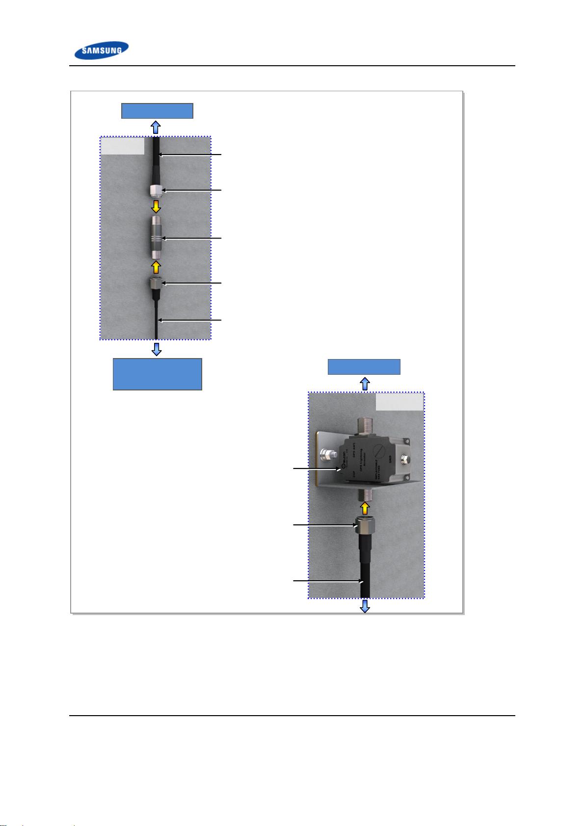
1 Install the GPS cable from the GPS antenna port of the 4G LTE Network Extender to
GPS arrestor.
2 Connect the assembled connectors of the cable to the GPS antenna port.
o RG-316D Cable: SMA Male 4G LTE Network Extender), N Type-Male (GPS Arrestor)
o LMR-400 Cable: N Type-Male (GPS Arrestor EQP)
GPS Antenna
4G LTE NE
4G LTE Network Extender GPS Arrestor Cable Connection (Case #1)
Follow the steps below to connect the GPS cable from the 4G LTE Network
Extender to the GPS arrestor.
Figure 24. 4G LTE Network Extender GPS Arrestor Cable Connection Case #1
Verizon 4G LTE Network Extender for Enterprise Installation Manual v1.0 57
©Samsung
Page 58

Appendix B Optional GPS Antenna Installation
Detail ‘A’
SMA Male Connector
GPS Cable (RG-316D)
‘A’
‘C-
1’
[GPS Arrestor]
[GPS
Antenna]
[4G LTE NE]
GPS Cable
(RG-316D)
GPS Cable
(LMR-400)
4G LTE NE
‘B’
[Adaptor]
GPS Cable
(LMR-400)
1 Install the GPS cable from the GPS antenna port of the 4G LTE Network Extender to GPS
arrestor.
2 Connect the assembled connectors of the cable to the GPS antenna port.
o RG-316D Cable: SMA Male (4G LTE Network Extender), N Type-Male (Straight Adaptor)
o LMR-400 Cable: N Type-Male (GPS Arrestor EQP)
‘D’
‘C-
2’
GPS Arrestor
4G LTE Network Extender GPS Arrestor Cable Connection (Case #2)
Figure 25. 4G LTE Network Extender GPS Arrestor Cable Connection Case #2
Verizon 4G LTE Network Extender for Enterprise Installation Manual v1.0 58
©Samsung
Page 59
Appendix B Optional GPS Antenna Installation
Detail ‘B’
GPS Cable (RG-316D)
N Type-Male Connector
Straight Adaptor
N Type-Male Connector
GPS Cable (LMR-400)
Detail ‘C-
GPS Arrestor
N Type-Male Connector
GPS Cable (LMR-400)
GPS Arrestor
GPS Antenna
4G LTE Network
Extender
Figure 26. 4G LTE Network Extender GPS Arrestor Cable Connection Details
Verizon 4G LTE Network Extender for Enterprise Installation Manual v1.0 59
©Samsung
Page 60

Appendix B Optional GPS Antenna Installation
Detail ‘C-2’
GPS Arrestor
N Type-Male Connector
GPS Cable (LMR-400)
GPS Cable (LMR-400)
GPS Antenna
Clamp
Clamp fixing Screw
Bakelite
GPS Antenna Fixing Pipe
TNC Male Connector
Heat Shrink Tube
Heat Shrink Tube (Jelly Type)
Detail ‘D’
1 Install the GPS cable from the GPS ANT. port of the GPS arrestor to the GPS antenna.
2 Connect the assembled connectors of the GPS cable (LMR-400) to the GPS arrestor and
antenna port.
LMR-400 Cable: N Type-Male (GPS Arrestor EQP)
TNC Type-Male (GPS Antenna)
GPS Antenna
Straight Adaptor
Figure 27. GPS Arrestor GPS Antenna Cable Connection Detail
Verizon 4G LTE Network Extender for Enterprise Installation Manual v1.0 60
©Samsung
Page 61

Appendix B Optional GPS Antenna Installation
GPS Satellite Tracking and Position Hold
The survey of an object’s position using GPS satellites is based on triangulation.
Three satellites are enough to survey the position of an object by triangulation.
However, to calculate the correct time deviation, a total of four satellites are
required.
Usually, the GPS antenna is installed in a high place, such as on a roof. It must be
installed away from protruding objects, such as trees or buildings. In addition, it
must be positioned away from any obstacle that covers part of the airspace around
the horizon of the building where it is installed.
If it is impossible to ensure a completely open airspace, you should install the GPS
antenna facing the equator providing a maximum view of the Southern sky
(Northern sky in the Southern hemisphere).
Furthermore, when installing the GPS antenna using a steel cylinder structure
shared by other RF antennas, it must be separated by more than 1 m from that steel
structure.
Figure 28. GPS Antenna Installation
Lightening Arrestor
A lightning arrestor is required when there is a danger of lightning striking a cable
or related part. The lightning arrestor must be installed in a place where the
antenna cable or set of combined cables enters a building or station, or a place
inside the building or station. The purpose of this is to protect the people and
equipment inside the building or station.
If struck directly by lightning, the lightning arrestor, antenna, or cable must be
replaced. Furthermore, you must inspect the lightening arrestor periodically, and
replace the antenna and cable periodically to ensure protection if lightning occurs
frequently at the site.
The lightning arrestor must be well grounded so that it can transmit a large current
quickly.
Verizon 4G LTE Network Extender for Enterprise Installation Manual v1.0 61
©Samsung
Page 62

Appendix B Optional GPS Antenna Installation
Signal Interference
The GPS system is designed so that it has a strong immunity to noise and can
endure interference.
The Samsung GPS receiver provides a quality timing clock in most installations.
However, to ensure that the GPS receiver performs locking successfully and
guarantees uninterrupted timing performance, an interference-free environment is
required for frequencies near the GPS L1 frequency (1575.42 ± 1 MHz).
Interference Types
There are two types of interference which affect the GPS L1 frequency:
Narrow band (inband) interference
When a frequency deviation (3.5 kHz), such as an FM wave, inflows in around
the GPS L1 frequency (1575.42 MHz), it is called narrow band (inband)
interference. Narrow band interference is monitored by the spectrum analyzer.
Because it has a time lag, a locking failure or a different type of alarm can
occur.
Wideband interference
When around the GPS L1 frequency (1575.42 MHz) and the frequency
deviation is more than 7 kHz, this is called wide band interference.
Wideband interference includes the interference induced by the harmonics
from a communication service with a different frequency bandwidth, increased
thermal noise from communication services around the L1 band, inflow of
interference due to unauthorized communication, saturation due to oscillation
of an accessory device, and so on.
You cannot monitor these kinds of interferences with a device such as a
spectrum analyzer. If the system has a wideband interference problem, you
should consult an expert in this area.
For other bandwidths, except the GPS L1 frequency (1575.42 ± 1 MHz), a GPS
Band Pass Filter (BPF) must be included within the GPS antenna to remove the
interference from the GPS bandwidth. No outband interference must affect the
GPS signals.
Avoiding Interferences
If more than one antenna for other communications, such as an antenna for a base
station or satellite communication, is installed at the facility, the GPS antenna must
be installed in a location to which no interference signals flow in.
If interference exists within the GPS L1 frequency bandwidths (1575.42 ± 1
MHz), you should use a band pass filter .
Verizon 4G LTE Network Extender for Enterprise Installation Manual v1.0 62
©Samsung
Page 63

Appendix B Optional GPS Antenna Installation
Furthermore, if the GPS antenna is installed near a transmitter which operates with
a bandwidth similar to the GPS L1 frequency, the possibility of interference
increases (in this case, interference is caused by harmonics). If the GPS antenna
has an interference problem , you must move it to a different location where
interference signals can be avoided or minimized.
Inband Noise
Inband noise includes narrow band noise and wide band noise that occur in an
inband width. (L1, 1575.42 ± 1 MHz)
- Narrow band noise in an inband width: If it is higher than 108 dBm, it can affect
the operation of the GPS receiver.
- Wideband noise in an inband width: It may not be detected by a measuring
instrument and impair the sensitivity of the GPS receiver and affect its operation.
If there is an outband interference problem, you can reduce the effects of
interference on the GPS receiver by applying one or more L1 GPS band pass
filters.
The filter should be installed at the following locations:
The input connector of the Samsung GPS receiver
Behind the antenna or the front end of a line amplifier
The filters above are used to reject jamming tones for outband signals. If
interferences actually occur in the inband signals, they will result in serious
consequences.
Verizon 4G LTE Network Extender for Enterprise Installation Manual v1.0 63
©Samsung
Page 64
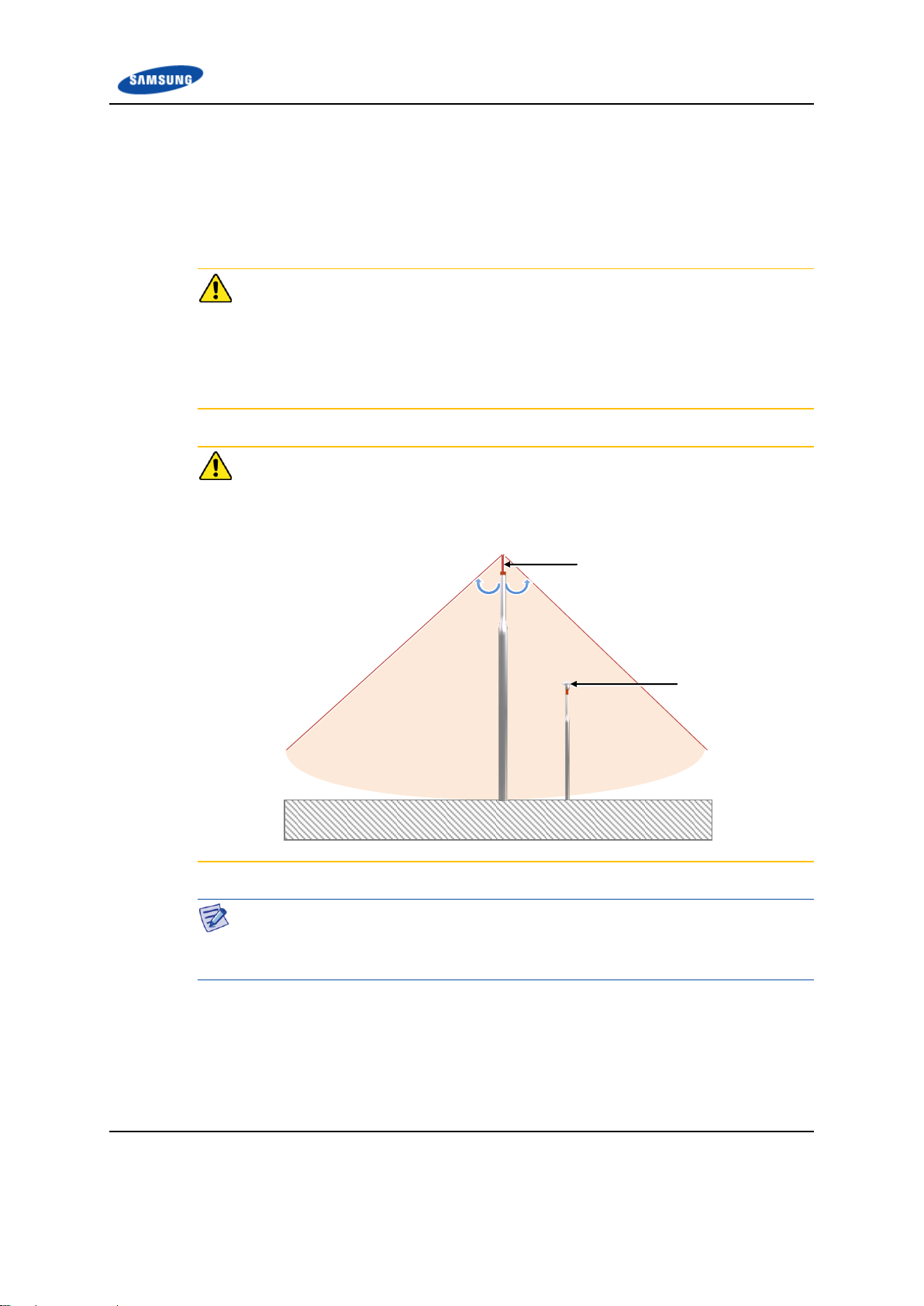
Appendix B Optional GPS Antenna Installation
Lightning Rod
45°
45°
GPS Antenna
GPS Antenna Installation
The GPS antenna can be fixed to a wall, floor, tower, pole or as recommended by
the manufacturer of the outdoor GPS antenna. . Ensure that you are safe when
fixing an anchor bolt to a wall and treat the anchor bolt fixing area with a silicon or
waterproof finishing material.
Installing the Concrete Block
A concrete block should be installed that satisfies the specification regarding size
and strength. When installing the concrete block, and before forming the concrete,
steel reinforcement bars should be arranged in a mesh layout at 3.93 in. (100 mm)
intervals before forming the concrete. (Either an anchor bolt assembly or a
concrete anchor can be used.)
Installing the Antenna
When you install the antenna, the antenna must be within the protective angle
(left/right side 45° each from the central axis) to prevent the antenna from
lightning damage.
Distance between the Antennas
When installing an antenna, 3.28~4.92 ft (1~1.5 m) distance must be secured
between the antennas to prevent interference.
Verizon 4G LTE Network Extender for Enterprise Installation Manual v1.0 64
©Samsung
Page 65

Appendix B Optional GPS Antenna Installation
GPS Antenna Wall Fixing
Pipe (Ф25.4 mm)
GPS Antenna
Bakelite
GPS Antenna Clamp
GPS Antenna
Wall Fixing Clamp Assembly
≒Min. 500 mm
Wall Mount GPS Antenna
Figure 29. GPS Antenna Installation (Wall)
Verizon 4G LTE Network Extender for Enterprise Installation Manual v1.0 65
©Samsung
Page 66

Appendix B Optional GPS Antenna Installation
GPS Antenna Floor Fixing Pipe
(Ф25.4 mm)
GPS Antenna
Bakelite
GPS Antenna Clamp
M10 Anchor Bolt Assembly
≒Min. 500 mm
Concrete Block
≒Min. 400
mm
≒Min. 250 mm
Floor Mount GPS Antenna
Figure 30. GPS Antenna Installation (Floor)
Verizon 4G LTE Network Extender for Enterprise Installation Manual v1.0 66
©Samsung
Page 67

Appendix B Optional GPS Antenna Installation
Classification
Description
Installation Position
An arrestor must be installed within the lightning rod protection angle.
The arrestor must be installed to prevent a person or system being affected by
lightning induced currents.
Parts
Bulkhead
Bakelite
1 EA
1 EA
Fastener
M6 Anchor Bolt Assembly
M6 Anchor Bolt
M6 Hex. Nut
M6 Spring Washer
M6 Plane Washer
2 sets
1 EA/set
1 EA/set
1 EA/set
1 EA/set
M6 Insulation Bushing
2 EA
Recommended
Torque Value
M6 Hex. Nut
2.41~3.61 ft.lb.
(33.28~49.92 kgf.cm)
Working Tools
Drill, Hammer, Torque Wrench, Level
Installing Optional GPS Arrestor
Fixing GPS Bulkhead
The method to fix the GPS bulkhead is as follows.
Table 21. Optional GPS Bulkhead Fixing Parts and Tools
Verizon 4G LTE Network Extender for Enterprise Installation Manual v1.0 67
©Samsung
Page 68

Appendix B Optional GPS Antenna Installation
1 Fix the anchor bolts to the holes marked and drilled.
Drill bit: 0.39 in.(10 mm) / Hole depth: 1.3 in.(33 mm)
2 Place the Bakelite and bulkhead along with the fixed anchor bolts. Secure firmly using fasteners.
3.58 in.(91 mm)
0.39 in.(10 mm)
0.39 in.(10 mm)
2.28 in.(58 mm)
0.98 in.
(25 mm)
Bulkhead
(Front View)
M6 Anchor Bolt
Bakelite
Bulkhead
M6 Insulation Bushing
M6 Plane Washer
M6 Spring Washer
M6 Hex. Nut
Figure 31. Fixing GPS Bulkhead
Verizon 4G LTE Network Extender for Enterprise Installation Manual v1.0 68
©Samsung
Page 69

Appendix B Optional GPS Antenna Installation
Classification
Description
Parts
GPS Arrestor/1 Set
GPS Arrestor Unit
1 EA/GPS Arrestor
Fastener
N Type Nut
1 EA/GPS Arrestor
Plane Washer
1 EA/GPS Arrestor
Recommended
Torque Value
N Type Nut
3.25~3.61 ft.lb.
(44.93~49.91 kgf.cm)
Working Tools
Torque Wrench, Spanner
GPS Arrestor
Bulkhead
Plane Washer
N Type Nut
1 Insert the connector for the GPS arrestor along with the bulkhead fixing hole.
2 Secure the GPS arrestor with the bulkhead using fasteners. Make sure that the system-
side and antenna-side connector directions are not changed.
Check the Configurations of GPS Arrestor and Bulkhead
The fixing methods and fasteners vary for the configurations of the GPS arrestor
and bulkhead. Thus, check the installation methods and configurations enclosed
with the GPS arrestor and bulkhead.
Fixing GPS Arrestor
The method to fix the GPS arrestor is as follows.
Table 22. GPS Arrestor Fixing Parts and Tools
Figure 32. Fixing the GPS Arrestor
Verizon 4G LTE Network Extender for Enterprise Installation Manual v1.0 69
©Samsung
Page 70

Appendix B Optional GPS Antenna Installation
Classification
Description
Installation Section
MGB Ground Terminal of Arrestor
Cable
AWG8, F-GV 6 mm2 × 1C/1 EA
Heat Shrink Tube
(Spec/Color/Length)
Ф 0.4 in. (10 mm)/Green/1.97 in. (50 mm)
Pressure Terminal
MGB
Checking the MGB specifications per site and preparing
fasteners
Arrestor
6 mm2, Ring type, Hole Dia.: 0.21 in. (5.3 mm)
Fastener
MGB
Checking the MGB specifications per site and preparing
fasteners
Arrestor
M5 Hex. Bolt/1 EA
M5 Spring Washer/1 EA
M5 Plane Washer/1 EA
(attached at the GPS arrestor)
Recommended Torque
Value (kgf.cm)
M5 Hex. Bolt
1.45~2.17 ft.lb. (20 ~ 30 kgf.cm)
Working Tools
Cable Cutter, Wire Stripper, Compressor, Heating Gun, Torque Driver (+), Torque
Wrench, Nipper
Grounding the Optional GPS Arrestor
The way to connect the ground cable with the GPS arrestor is as follows.
Table 23. Grounding the GPS Arrestor (MGB GPS Arrestor)
Pressure Terminal for Grounding
As for the pressure terminal or the cable, the UL Listed products or equivalent
should be used.
For example:
Manufacturer: JEONO Electric
GPS Arrestor: 6 mm2 Pressure Terminal (JOR 6-5)
Assembling a Pressure Terminal and a Heat Shrink Tube
Refer to Appendix D to see how to assemble a pressure terminal and a heat shrink
tube to a cable.
Verizon 4G LTE Network Extender for Enterprise Installation Manual v1.0 70
©Samsung
Page 71

Appendix B Optional GPS Antenna Installation
GPS Arrestor Ground Cable
(AWG8, F-GV 6 mm2 × 1C)
Heat Shrink Tube (Green)
GPS Arrestor Ground Cable
MGB
1 Install a ground cable from the MGB to the GPS arrestor ground terminal.
2 Assemble a pressure terminal and a heat shrink tube at the end of the ground cable (GPS arrestor-side).
3 Align the pressure terminal assembled to a ground cable to the mounting hole of the GPS arrestor ground
terminal.
4 Firmly fix the pressure terminal onto the GPS arrestor using fasteners.
[GPS Arrestor]
6 mm2 Pressure Terminal (Ring Type)
M5 Plane Washer
M5 Spring Washer
M5 Hex. Bolt
Figure 33. Connection of the GPS Arrestor Ground Cable
Verizon 4G LTE Network Extender for Enterprise Installation Manual v1.0 71
©Samsung
Page 72

Appendix C Installing the
Feeder Cable
Cautions When Installing Feeder Cable
When installing the feeder cable (GPS/RF cable), the following cautions shall be
considered:
Ensure any mounting plates used in installation do not damage the surface of
the feeder cable.
Attach the cognitive tapes to both ends of the feeder cable, which makes it
easy to recognize.
When connecting the antenna and lightning arrestor to the feeder cable, use
proper torque to prevent reflected waves.
The curvature radius should be maximized during installation. Do not exceed
the minimum curvature radius.
Verizon 4G LTE Network Extender for Enterprise Installation Manual v1.0 72
©Samsung
Page 73

Appendix C Installing the Feeder Cable
Specification
Allowed Radius of
Curvature
Remark
LS Feeder Line
HFC-12D
1/2 in.
4.02 in.(125 mm)
Outdoor
HFC-22D
7/8 in.
9.84 in.(250 mm)
HFC-33D
1-1/4 in.
14.96 in.(380 mm)
HFC-42D
1-5/8 in.
20.08 in.(510 mm)
RFS Feeder Line
LCF12-50
1/2 in.
4.92 in.(125 mm)
LCF78-50
7/8 in.
9.84 in.(250 mm)
LCFS114-50
1-1/4 in.
14.96 in.(380 mm)
LCF158-50
1-5/8 in.
19.69 in.(500 mm)
Specification
Allowed Radius of Curvature
Remark
LMR-400
1 in. (25.4 mm)
Installation
4 in.(101.6 mm)
Repeater
1/2 in.
7/8 in.
1-1/4 in.
1-5/8 in.
Table 24. Curvature Radius of Feeder Cable for Outdoor
Table 25. Curvature Radius of Feeder Cable for Indoor (Based on LS Feeder Line)
Verizon 4G LTE Network Extender for Enterprise Installation Manual v1.0 73
©Samsung
Radius of Curvature of the Feeder Line
When installing a feeder line, the radius of curvature of the sections where cables
are bent should be larger than the allowed radius of curvature. If the radius of
curvature for the feeder line installation is less than the allowed radius of
curvature, it may affect the performance of the system.
Ensure that the feeder cable does not interfere with steel towers, ladders and in the
areas chiefly used by people.
Page 74

Appendix C Installing the Feeder Cable
Connector
Torque Value
SMA connector
0.18 ft.lb.(2.5 kgf•cm)
TNC connector
0.65 ft.lb.(9 kgf•cm)
N-type connector
1.45 ft.lb.(20 kgf•cm)
Din-type connector
14.46 ft.lb.(200 kgf•cm)
Connect the connector to the antenna in a straight line and after connecting, do not
apply excessive force.
Use the vinyl tape and the heat shrink tube for the external exposed part of the
connector to prevent damage from water seepage.
Wind the self-bonding rubber tape overlapping (keep a distance as the half size of
rubber tape) to the connector connection part and wind the vinyl tape for any
electric wiring two times or more, and then cover with the jelly type heat shrink
tube.
Connection of the Feeder Cable Connector
Connecting the feeder cable connector is a critical process, so the qualified
workers who finished the related education should perform.
Table 26. Connector Connection Torque Value
Verizon 4G LTE Network Extender for Enterprise Installation Manual v1.0 74
©Samsung
Page 75

1) and 2) Prepare work tools and materials.
4) Pass the cable through the
RJ-45 cap.
5) Remove the coating 17 mm
from the end.
6) Push the shield backward,
and cut the aluminum shield.
7) Cut the shield leaving 5 mm
of it.
8) Arrange the cable in reference
to the pin map.
9) Cut the cable to make it
12 mm long.
3) Pass the cable through the
marking tube.
1 2 3 4 5 6 7 8
9
Appendix D Connector
Assembly
RJ-45 (Shield Type)
The procedure that assembles the RJ-45 (shield type) connector is as follows.
Figure 34. Assembling the RJ-45 Connector (Shield Type) (1)
Verizon 4G LTE Network Extender for Enterprise Installation Manual v1.0 75
©Samsung
Page 76

Appendix D Connector Assembly
10) Insert the RJ-45 modular jack.
11) Make sure that the shield
does not get in the RJ-45
modular jack.
12) Insert the cable completely
into the RJ-45 modular jack.
13) Compress the jack using the tool.
14) Compress the marking tube to finish the
assembly.
10
11
12
13
14
Figure 35. Assembling the RJ-45 Connector (Shield Type) (2)
Verizon 4G LTE Network Extender for Enterprise Installation Manual v1.0 76
©Samsung
Page 77

Appendix D Connector Assembly
1) Prepare work tools and
materials.
2) Insert the RJ-45 cap into the
cable.
3) Remove the coating 17 mm
from the end.
4) Arrange the cable in reference
to the pin map.
5) Cut the cable to make it 12 mm
long.
1
2 3 4 5 6
7
8
7) Compress the jack using the
tool.
6) Insert the cable completely
into the RJ-45 modular jack.
8) Push the RJ-45 cap to the
connector.
RJ-45 (Normal Type)
The procedure that assembles the RJ-45 (normal type) connector is as follows.
Figure 36. Assembling the RJ-45 Connector (Normal Type)
N type-male (LMR-400)
The procedure for assembling the N type-male cable connector to LMR-400 cable
is as follows.
Verizon 4G LTE Network Extender for Enterprise Installation Manual v1.0 77
©Samsung
Page 78

Appendix D Connector Assembly
1) The components of the N type-male include
N type-male body, clamp ring, and heat shrink
tube.
2) Insert a heat shrink tube and clamp ring to the
cable, and insert the cable into the ‘End1’ of the
prep/strip tool. Then remove the shield and
sheath except for the center conductor at the end
of the cable by rotating the tool clockwise.
3) Insert the cable into the ‘End2’ of the
prep/strip tool again, and remove the sheath
except for the shield by rotating the tool.
4) Trim the end of the center conductor by using
a deburring tool.
Heat Shrink Tube
Clamp Ring
N type-Male Body
LMR-400
LMR-400
Prep/strip Tool
Prep/strip Tool
Deburring tool
Center Conductor
Shield
Clamp Ring
Heat
Shrink
Figure 37. N type-male Connector Assembling (1)
Verizon 4G LTE Network Extender for Enterprise Installation Manual v1.0 78
©Samsung
Page 79

Appendix D Connector Assembly
5) Push a connector into the end of the cable.
Then, push it further until the center conductor is
firmly inserted into the pin connection part of the
N-Type male body.
Make the shield overlap the N-Type male body,
pull out the clamp ring, and let it go to its original
position so that the remaining length may be
folded.
6) Cut off the folded length of the shield using a
cutting device so that it does not protrude outside
when the clamp ring is inserted.
After arranging the shield, push up the clamp ring
toward the connector until the entire shield is
covered.
7) Using a compressor and hexagonal dies,
pressurize the clamp ring to fix the cable and
connector.
8) Lift the heat shrink tube up to the connection
point on the connector and shrink the heat shrink
tube using a heating gun.
Figure 38. N type-male Connector Assembling (2)
Verizon 4G LTE Network Extender for Enterprise Installation Manual v1.0 79
©Samsung
Page 80

Appendix D Connector Assembly
1) The components of the TNC-male include
TNC-male body, clamp ring, and heat shrink
tube.
2) Insert a heat shrink tube and clamp ring to
the cable, and insert the cable into the ‘End1’ of
the prep/strip tool. Then, remove the shield and
sheath except for the center conductor at the
end of the cable by rotating the tool clockwise.
3) Insert the cable into the ‘End2’ of the
prep/strip tool again, and remove the sheath by
rotating the tool.
4) Trim the end of the center conductor by
using a deburring tool.
Heat Shrink Tube
Clamp Ring
TNC-Male Body
Prep/strip tool End1
Prep/strip tool End2
Deburring tool
Clamp Ring
Heat Shrink
Tube
LMR-400
Center Conductor
LMR-400
Shield
TNC-male (LMR-400)
The procedure for assembling the TNC-male cable connector to LMR-400 cable is
as follows.
Figure 39. TNC-male Connector Assembling (1)
Verizon 4G LTE Network Extender for Enterprise Installation Manual v1.0 80
©Samsung
Page 81

Appendix D Connector Assembly
5) Push a connector into the end of the cable.
Then, push it further until the center conductor is
firmly inserted into the pin connection part of the
N-Type male body.
Make sure the shield overlaps the N-Type male
body, pull out the clamp ring, and let it return to
its original position so that the remaining length is
folded.
6) Cut off the folded length of the shield using a
cutting device so that it does not protrude outside
when the clamp ring is inserted.
After arranging the shield, push up the clamp ring
toward the connector until the entire shield is
covered.
7) Using a compressor and hexagonal dies,
pressurize the clamp ring to fix the cable and
connector.
8) Lift the heat shrink tube up to the connection
point on the connector and shrink the heat shrink
tube using a heating gun.
Figure 40. TNC-male Connector Assembling (2)
Verizon 4G LTE Network Extender for Enterprise Installation Manual v1.0 81
©Samsung
Page 82

Verizon 4G LTE Network Extender for Enterprise Installation Manual v1.0 82
©Samsung
Page 83

Appendix E
Bolt Spec.
Torque Value (kgf.cm)
Torque Value (N.m)
Torque Value (ft.lb.)
M3
4.08~6.12
0.40~0.60
0.29~0.44
M4
9.52~14.28
0.93~1.40
0.69~1.03
M5
20.0~30.0
1.96~2.94
1.45~2.17
M6
33.28~49.92
3.26~4.90
2.41~3.61
M8
82.4~123.6
8.08~12.12
5.96~8.94
M10
166.4~249.6
16.32~24.48
12.03~18.05
M12
292.0~438.0
28.64~42.65
21.11~31.67
Bolt Spec.
Torque Value (kgf.cm)
Torque Value (N.m)
Torque Value (ft.lb.)
M6
29.98 ± 10 %
2.94 ± 10 %
2.17 ± 10 %
M8
64.26 ± 10 %
6.3 ± 10 %
4.16 ± 10 %
Standard Torque
Appendix E
When you tighten the bolt, refer to the standard torque value below to prevent the
equipment and bolt from damage, and secure by tightening. When the torque value
for each connection part is defined already, refer to the defined value.
Table 27. Standard Torque Value for Tightening Bolts
Standard Torque
Table 28. Brass Bolts Torque Value
Check the Standard Torque Value
The torque value can be different, depending on the material, characteristics and
specifications for the equipment and fastener. Make sure to check the proper
torque value for each specification of the equipment and fastener.
Verizon 4G LTE Network Extender for Enterprise Installation Manual v1.0 83
©Samsung
Page 84

Appendix F Acronyms
EMC Electromagnetic Compatibility
FTP File Transfer Protocol
GPS Global Positioning System
LMT Local Maintenance Tool
LTE Long Term Evolution
MGB Main Ground Bar
RF Radio Frequency
VSWR Voltage Standing Waveform Ratio
Verizon 4G LTE Network Extender for Enterprise Installation Manual v1.0 84
©Samsung
Page 85

Verizon 4G LTE
Network Extender for Enterprise
Installation Manual
Document Version 1.1
©2014 Samsung Electronics Co., Ltd.
All rights reserved.
 Loading...