

Page 1

Verizon FiOS® Router
Model 9100VM
User Guide
www.verizon.com/fios
Page 2

Verizon FiOS Router (Model 9100VM)
User Guide
CONTENTS
PRODUCT DESCRIPTION ..................................................................................................................................5
1.
2. SAFETY INSTRUCTIONS...................................................................................................................................5
3. REGULATORY INFORMATION........................................................................................................................6
3.1 FCC Compliance Note...............................................................................................................................6
3.2 Canada Certification Notice.......................................................................................................................7
4. NETWORKING REQUIREMENTS .....................................................................................................................8
5. HARDWARE FEATURES....................................................................................................................................9
5.1 LED Indicators...........................................................................................................................................9
5.2 Cable Connectors and Switch Locations..................................................................................................10
5.3 Connector Descriptions............................................................................................................................11
6. INSTALLING THE HARDWARE......................................................................................................................12
6.1 Installation Requirements ........................................................................................................................12
6.2 Before you begin......................................................................................................................................12
6.3 Microfilters ..............................................................................................................................................12
6.4 Hardware Installations .............................................................................................................................13
7. ACCESSING THE ROUTER ..............................................................................................................................18
7.1 Logging on to the Router ......................................................................................................................... 18
8. CONFIGURING YOUR BROADBAND CONNECTION .................................................................................21
8.1 Confirming Your VDSL2 Connection..................................................................................................... 21
8.2 Connecting to the Internet........................................................................................................................21
8.3 Logging Out of the Router’s Web Pages .................................................................................................25
9. SETTING UP MACINTOSH OS X.....................................................................................................................26
9.1 Opening the System Preference Screen ................................................................................................... 26
9.2 Choosing the Network Preferences..........................................................................................................26
9.3 Creating a New Location ......................................................................................................................... 27
9.4 Naming the New Location.......................................................................................................................27
9.5 Selecting the Ethernet Configuration.......................................................................................................27
9.6 Checking the IP Connection ....................................................................................................................28
9.7 Accessing Your Router ............................................................................................................................29
10. BASIC CONFIGURATION ................................................................................................................................30
11. MAIN (HOME PAGE).........................................................................................................................................31
11.1 Gateway Status ........................................................................................................................................32
030-300239 Rev. A 2 March 2008
Page 3

Verizon FiOS Router (Model 9100VM)
Quick Links..............................................................................................................................................32
11.2
User Guide
11.3 Network Connections...............................................................................................................................32
11.4 Start Surfing.............................................................................................................................................32
12. WIRELESS ..........................................................................................................................................................33
12.1 Wireless Status......................................................................................................................................... 33
12.2 Basic Security Settings ............................................................................................................................34
12.3 Advanced Security Settings ..................................................................................................................... 37
13. MY NETWORK...................................................................................................................................................57
13.1 Network Status......................................................................................................................................... 57
13.2 Network Connections...............................................................................................................................74
14. FIREWALL SETTINGS....................................................................................................................................110
14.1 General Firewall Security Settings.........................................................................................................110
14.2 Access Control.......................................................................................................................................111
14.3 Port Forwarding ..................................................................................................................................... 120
14.4 DMZ Host..............................................................................................................................................137
14.5 Port Triggering.......................................................................................................................................138
14.6 Remote Admin.......................................................................................................................................147
14.7 Static NAT .............................................................................................................................................148
14.8 Advanced Filtering.................................................................................................................................153
14.9 Security Log........................................................................................................................................... 156
14.10 Connections ...........................................................................................................................................158
15. PARENTAL CONTROLS .................................................................................................................................160
16. ADVANCED......................................................................................................................................................165
16.1 Diagnostics.............................................................................................................................................166
16.2 Restore Defaults..................................................................................................................................... 168
16.3 Reboot....................................................................................................................................................169
16.4 MAC Cloning ........................................................................................................................................170
16.5 ARP Table..............................................................................................................................................171
16.6 Users ......................................................................................................................................................173
16.7 Quality of Service .................................................................................................................................. 179
16.8 Remote Administration..........................................................................................................................190
16.9 DNS .......................................................................................................................................................191
16.10 Personal Domain (Dynamic DNS).........................................................................................................192
16.11 Network Objects ....................................................................................................................................194
030-300239 Rev. A 3 March 2008
Page 4

Verizon FiOS Router (Model 9100VM)
Protocol..................................................................................................................................................197
16.12
User Guide
16.13 UPnP ......................................................................................................................................................210
16.14 System Settings...................................................................................................................................... 211
16.15 Configuration File..................................................................................................................................212
16.16 Date and Time Rules..............................................................................................................................213
16.17 Scheduler Rules .....................................................................................................................................213
16.18 Firmware Upgrade ................................................................................................................................. 214
16.19 Routing...................................................................................................................................................215
16.20 IGMP Configuration ..............................................................................................................................218
16.21 PPPoE Relay ..........................................................................................................................................221
16.22 IP Address Distribution..........................................................................................................................222
17. SYSTEM MONITORING..................................................................................................................................223
18. TECHNICAL SUPPORT INFORMATION......................................................................................................225
19. PRODUCT SPECIFICATIONS.........................................................................................................................225
20. SOFTWARE LICENSE AGREEMENT............................................................................................................226
21. PUBLICATION INFORMATION.....................................................................................................................228
030-300239 Rev. A 4 March 2008
Page 5
Verizon FiOS Router (Model 9100VM)
1. PRODUCT DESCRIPTION
User Guide
The Verizon
and is capable of data rates hundreds of times faster than a traditional analog modem. But unlike analog modems,
the Verizon FiOS Router allows you to use the same phone line for simultaneous voice/fax communications and
high-speed Internet access, eliminating the need for dedicated phone lines for voice and data needs. In addition, your
Verizon FiOS Router supports a variety of networking interfaces such as Wireless 802.11b/g, VDSL2, COAX, and
WAN Ethernet.
Hereafter, the Verizon
Key Features:
• Multimedia over Coax interface (MoCA)
• 4-Port 10/100 BaseT Ethernet LAN switch
• Integrated 802.11g Access Point
• Embedded Firewall
• IP Quality of Service
• IGMP Proxy Function
®
FiOS® Router provides reliable, high-speed, Internet access to your existing small office phone line
®
FiOS® Router will be referred to as the “Router,” or “Modem.”
2. SAFETY INSTRUCTIONS
• Never install any telephone wiring during a lightning storm.
• Never install telephone jacks in wet locations unless the jack is specifically designed for wet locations.
• Never touch non-insulated telephone wires or terminals unless the telephone line has been disconnected at
the network interface.
• Use caution when installing or modifying telephone lines.
WARNING
Risk of electric shock. Voltages up to 140 Vdc (with reference to
ground) may be present on telecommunications circuits.
030-300239 Rev. A 5 March 2008
Page 6

Verizon FiOS Router (Model 9100VM)
User Guide
3. REGULATORY INFORMATION
3.1 FCC Compliance Note
(FCC ID: CH89100VMXX-10)
This equipment has been tested and found to comply with the limits for a Class B digital device, pursuant to Part 15
of the Federal Communication Commission (FCC) Rules. These limits are designed to provide reasonable protection
against harmful interference in a residential installation. This equipment generates, uses, and can radiate radio
frequency energy, and if not installed and used in accordance with the instructions, may cause harmful interference
to radio communications. However, there is no guarantee that interference will not occur in a particular installation.
If this equipment does cause harmful interference to radio or television reception, which can be determined by
turning the equipment OFF and ON, the user is encouraged to try to correct the interference by one or more of the
following measures:
• Reorient or relocate the receiving antenna.
• Increase the separation between the equipment and the receiver.
• Connect the equipment to a different circuit from that to which the receiver is connected.
• Consult the dealer or an experienced radio/TV technician for help.
• This device complies with part 15 of the FCC Rules. Operation is subject to the following two conditions:
(1) this device may not cause harmful interference, and (2) this device must accept any interference
received, including interference that may cause undesired operation.
WARNING: While this device is in operation, a separation distance of at least 20 cm (8 inches) must be maintained
between the radiating antenna and users exposed to the transmitter in order to meet the FCC RF exposure guidelines.
Making changes to the antenna or the device is not permitted. Doing so may result in the installed system exceeding
RF exposure requirements. This device must not be co-located or operated in conjunction with any other antenna or
radio transmitter. Installers and end users must follow the installation instructions provided in this guide.
Modifications made to the device, unless expressly approved, could void the users’ rights to operate the device.
PART 68 – COMPLIANCE REGISTRATION
This equipment is designated to connect to the telephone network or premises wiring using a compatible modular
jack that is Part 68 compliant. An FCC compliant telephone cord and modular plug is provided with the equipment.
See the Installation Information section of this User Guide for details.
A plug and jack used to connect this equipment to the premises wiring and telephone network must comply with the
applicable FCC Part 68 rules and requirements adopted by the ACTA. A compliant telephone cord and modular plug
is provided with this product. It is designed to be connected to a compatible modular jack that is also compliant. See
installation instruction for details.
If this terminal equipment (Model 9100VM) causes harm to the telephone network, the telephone company may
request you to disconnect the equipment until the problem is resolved. The telephone company will notify you in
advance if temporary discontinuance of service is required. If advance notification is not practical, the telephone
company will notify you as soon as possible. You will be advised of your right to file a complaint with the FCC if
you believe such action is necessary. If you experience trouble with this equipment (Model 9100VM), do not try to
repair the equipment yourself. The equipment cannot be repaired in the field. Contact Verizon for instructions.
030-300239 Rev. A 6 March 2008
Page 7

Verizon FiOS Router (Model 9100VM)
The telephone company may make changes to their facilities, equipment, operations, or procedures that could affect
the operation of this equipment. If this happens, the telephone company will provide advance notice in order for you
to make the modifications necessary to maintain uninterrupted service.
If your home has specially wired alarm equipment connected to the telephone line, ensure that the installation of this
equipment (Model 9100VM) does not disable your alarm equipment. If you have questions about what will disable
alarm equipment, consult your telephone company or a qualified installer. This equipment cannot be used on public
coin phone service provided by the telephone company. Connection of this equipment to party line service is subject
to state tariffs.
User Guide
3.2 Canada Certification Notice
The Industry Canada label identifies certified equipment. This certification means that the equipment meets certain
telecommunications network protective, operations and safety requirements as prescribed in the appropriate
Terminal Equipment Technical Requirements document(s). The department does not guarantee the equipment will
operate to the user’s satisfaction.
This equipment meets the applicable Industry Canada Terminal Equipment Technical Specification. This is
confirmed by the registration number. The abbreviation, IC, before the registration number signifies that registration
was performed based on a Declaration of Conformity indicating that Industry Canada technical specifications were
met. It does not imply that Industry Canada approved the equipment. The Ringer Equivalence Number (REN) is 0.0.
The Ringer Equivalence Number that is assigned to each piece of terminal equipment provides an indication of the
maximum number of terminals allowed to be connected to a telephone interface. The termination on an interface
may consist of any combination of devices subject only to the requirement that the sum of the Ringer Equivalence
Numbers of all the devices does not exceed five.
Before installing this equipment, users should ensure that it is permissible to be connected to the facilities of the
local Telecommunication Company. The equipment must also be installed using an acceptable method of
connection. The customer should be aware that compliance with the above conditions may not prevent degradation
of service in some situations. Connection to a party line service is subject to state tariffs. Contact the state public
utility commission, public service commission, or corporation commission for information.
If your home has specially wired alarm equipment connected to the telephone line, ensure that the installation of this
equipment (Model 9100VM) does not disable your alarm equipment. If you have questions about what will disable
alarm equipment, consult your telephone company or a qualified installer.
If you experience trouble with this equipment (Model 9100VM), do not try to repair the equipment yourself. The
equipment cannot be repaired in the field and must be returned to the manufacturer. Repairs to certified equipment
should be coordinated by a representative, and designated by the supplier. Contact Verizon for instructions.
The termination on an interface may consist of any combination of devices subject only to the requirement that the
sum of the Ringer Equivalence Numbers of all the devices does not exceed five. Users should ensure, for their own
protection, that the electrical ground connections of the power utility, telephone lines, and internal, metallic water
pipe system, if present, are connected together. This precaution may be particularly important in rural areas.
Users should not attempt to make such connections themselves, but should contact the
appropriate electrical inspection authority, or electrician, as appropriate.
030-300239 Rev. A 7 March 2008
CAUTION
Page 8
Verizon FiOS Router (Model 9100VM)
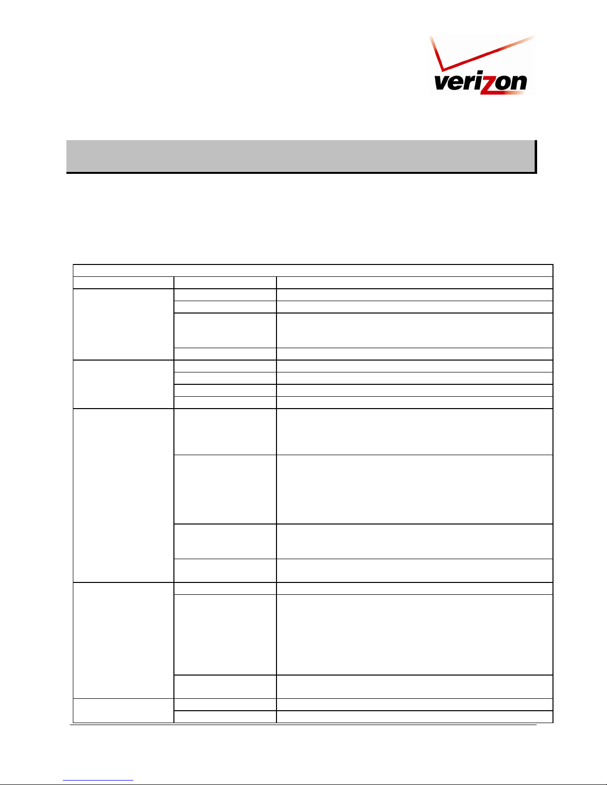
4. NETWORKING REQUIREMENTS
The following system specifications are required for optimum performance of the Router.
Connection Type Minimum System Requirements
ETHERNET
(1,2,3,4, WAN)
WIRELESS
IEEE 802.11b/g
COAX
• Pentium
• Microsoft
or Linux installed
• 64 MB RAM (128 MB recommended)
• 10 MB of free hard drive space
• 10/100 Base-T Network Interface Card (NIC)
• Internet Explorer 5.5 or later or Netscape Navigator 7.x or later or
• Firefox 1.0.7 or later
• Computer Operating System CD-ROM on hand
• Pentium
• Microsoft
or Linux installed
• 64 MB RAM (128 MB recommended)
• 10 MB of free hard drive space
• 10/100 Base-T Network Interface Card (NIC)
• Internet Explorer 5.5 or later or Netscape Navigator 7.x or later or
• Firefox 1.0.7 or later
• Computer Operating System CD-ROM on hand
• Pentium
• Microsoft
Macintosh® OS X installed
• 64 MB RAM (128 MB recommended)
• 10 MB of free hard drive space
• Internet Explorer 5.5 or Netscape Navigator 7.x or later or
• Firefox 1.0.7 or later
• An available IEEE 802.11b/g PC adapter
• Computer Operating System CD-ROM on hand
® or equivalent class machines or higher
® Windows® (XP, 2000, ME, NT 4.0, 98 SE) Macintosh® OS X,
® or equivalent class machines or higher
® Windows® (XP, 2000, ME, NT 4.0, 98 SE) Macintosh® OS X,
® or equivalent class or higher machines
® Windows® (XP, 2000, ME, NT 4.0, 98 SE) or
User Guide
030-300239 Rev. A 8 March 2008
Page 9
Verizon FiOS Router (Model 9100VM)
User Guide
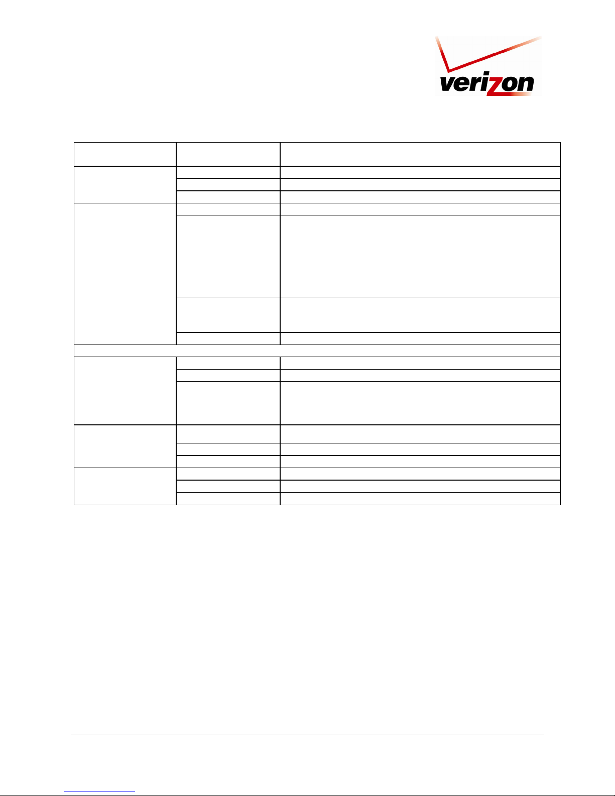
5. HARDWARE FEATURES
5.1 LED Indicators
This section explains the front-panel and rear-panel LED states and descriptions. LEDs are used to verify the unit’s
operation and status.
LED State Description
POWER
BROADBAND
INTERNET
WIRELESS
SETUP
(Ethernet LAN)
030-300239 Rev. A 9 March 2008
LED States and Descriptions
Verizon FiOS Router Front Panel LEDs
Solid Green Power is ON.
Flashing Green Router is performing POST.
Router failed POST (Power On Self Test) or Device Malfunction.
Solid Red
OFF Power is OFF.
Solid Green VDSL2 link established.
Flashing Green VDSL2 attempting to sync.
Solid Red Router failed to sync.
OFF Router power is OFF or no VDSL2 signal detected.
Solid Green
Flashing Green
Solid Amber
OFF
Solid Green Wireless link established.
Flashing Green
OFF
Solid Green Powered device is connected to the associated port. 1,2,3,4
Flashing Green 10/100 Base-T LAN activity is present (traffic in either direction).
Note: The Power LED should be red no longer than two seconds
after the power on self test passes.
Internet link established. VDSL2 link is Up, and the Router has a
WAN IP address from IPCP or DHCP; or a static IP is configured;
or PPP negotiation has successfully completed (if used) and no
traffic is detected.
IP connection established and IP Traffic is passing through device
(in either direction). Note: If the IP or PPP session is dropped due
to an idle timeout, the light will remain solid green, if a VDSL2
connection is still present. If the session is dropped for any other
reason, the light is turned OFF. The light will turn red when it
attempts to reconnect and DHCP or PPP fails).
Router has attempted and failed to establish IP connectivity (no
DHCP response, no PPP response, PPP authentication failed, no
IP address from IPCP, etc.).
Router power is OFF; or Router is performing POST; or Router is
in Bridge Mode; or Router has not attempted Internet connectivity.
Wireless LAN activity is present (traffic in either direction).
IP connection established and IP traffic is passing through device
(in either direction). Note: If the IP or PPP session is dropped due
to an idle timeout, the light will remain solid green, if a VDSL2
connection is still present. If the session is dropped for any other
reason, the light is turned OFF. The light will turn red when it
attempts to reconnect and DHCP or PPP fails).
Router power is OFF; no wireless link; or wireless Easy Config
not active.
Page 10
Verizon FiOS Router (Model 9100VM)
Router power is OFF, or no cable or no powered device is
connected to the associated port.
Wireless LAN activity is present (traffic in either direction).
IP connection established and IP traffic is passing through device
(in either direction). Note: If the IP or PPP session is dropped due
to an idle timeout, the light will remain solid green, if a VDSL2
connection is still present. If the session is dropped for any other
reason, the light is turned OFF. The light will turn red when it
attempts to reconnect and DHCP or PPP fails).
Device attempted to become IP connected and failed (no DHCP
response, no PPP response, PPP authentication failed, no IP
address from IPCP, etc.).
Rear Panel LEDs
POST (Power On Self Test), Failure (not bootable) or Device
Malfunction. Note: The Power LED should be red no longer than
two seconds after the power on self test passes.
COAX
WIRELESS
POWER
Left Ethernet LED
Right Ethernet LED
OFF
Solid Green A physical connection has been established.
Flashing Green Activity is present on the Coax link.
OFF Router power is OFF.
Solid Green Wireless link established.
Flashing Green
Solid Red
OFF Router power is OFF or No wireless link.
Solid Green Router power is ON.
OFF Router power is OFF.
Solid Red
Solid Green 100 Mbps link established.
Flashing Green LAN activity at 100 Mbps (traffic in either direction).
OFF No 100 Mbps link.
Solid Green 10 Mbps link established.
Flashing Green LAN activity at 10 Mbps (traffic in either direction).
OFF No 10 Mbps link.
5.2 Cable Connectors and Switch Locations
• Reset push button
• Four LAN Ethernet connectors (RJ-45)
• WAN Ethernet connector (RJ-45)
• Power connector (12 VDC) barrel
• OFF/ON power switch
• VDSL2 connector (RJ-11)
• Wireless 802.11b/g SMA connector and antenna
User Guide
030-300239 Rev. A 10 March 2008
Page 11
r
Verizon FiOS Router (Model 9100VM)
User Guide
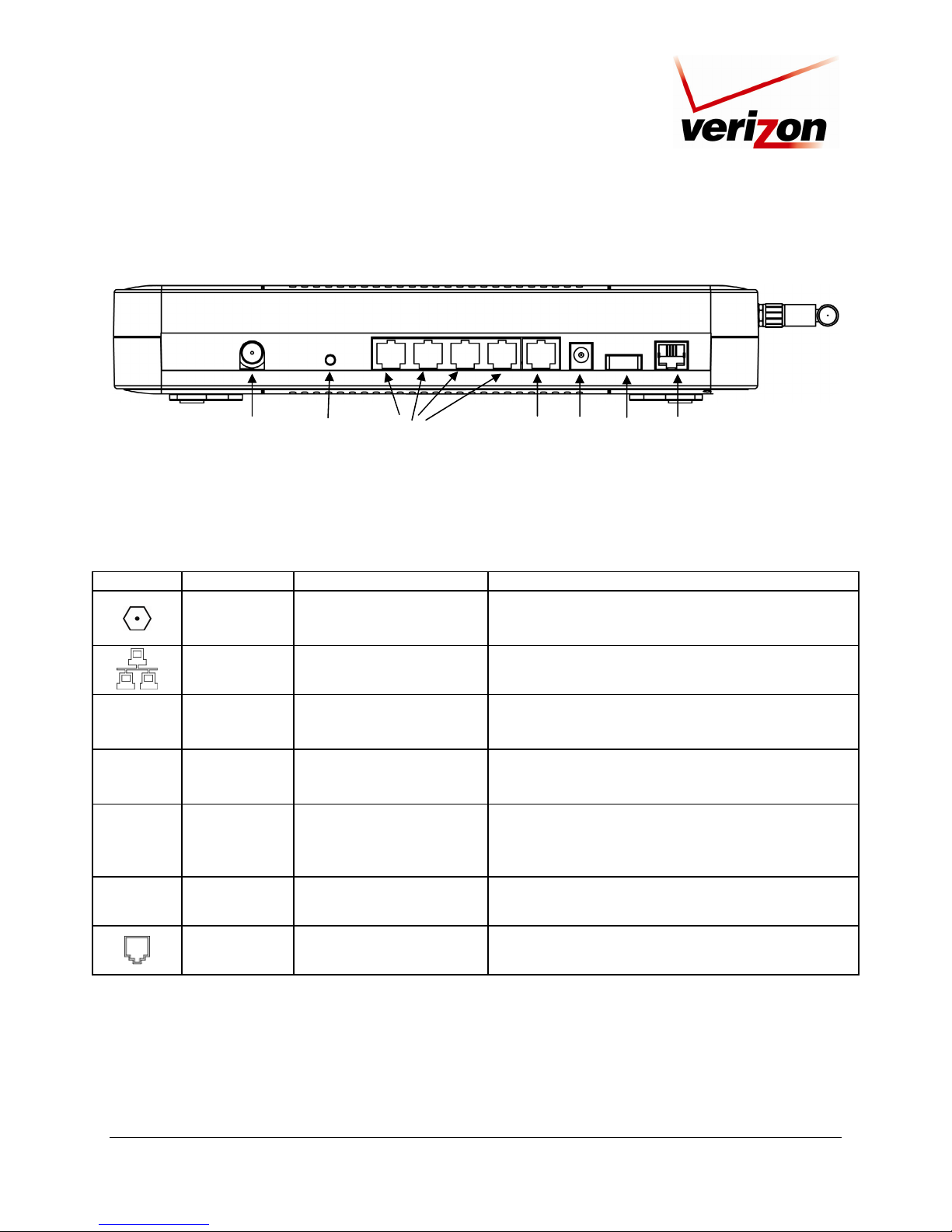
Verizon FiOS Router - Rear View
Wireless Antenna
and Connector
COAX
Connector
Reset
Button
Ethernet LAN
Connectors
(1,2,3,4)
Ethernet WAN
Connecto
Power
Connector
Off/On
Switch
VDSL2
Line
5.3 Connector Descriptions
The following chart displays the Router’s rear panel connector and switches.
SYMBOL NAME TYPE FUNCTION
<none>
12 VDC
Wireless
COAX F-type COAX connector
LAN 8-pin (RJ-45) modular jack
WAN 8-pin (RJ-45) modular jack
POWER Barrel connector
Wireless
Antenna
and
SMA connector and antenna
Connector
Connects the Router to the in-home coaxial cabling.
Compatible with the Multimedia over Coax Alliance
(MoCA) 1.1 standard.
Connects the Router’s 10/100 Base-T Ethernet switch to
a local computer, Hub, or other Ethernet-enabled device.
Connects the Router to a broadband modem or router
via 10/100 Base-T Ethernet, enabling access to the
Internet or Wide Area Network (WAN).
Connects the Router’s DC 12V power connector to an
AC wall jack. Use only the power supply provided with
the Router kit.
Antenna for transmitting and receiving wireless signals
for Wi-Fi (802.11b/g) connected devices.
<none>
POWER OFF/ON power switch Allows you to turn on or turn off the Router.
VDSL2 6-pin RJ-11 modular jack
030-300239 Rev. A 11 March 2008
Connects to a wall jack provisioned with VDSL2
service or to the VDSL2 jack of a POTS splitter.
Page 12
Verizon FiOS Router (Model 9100VM)
User Guide
6. INSTALLING THE HARDWARE
This section explains the hardware installation procedures for connecting to your Router.
6.1 Before you begin
Make sure that your kit contains the following items:
• Verizon
• Power Supply
• RJ-45 Ethernet cable (straight-through) (yellow)
• RJ-45 Ethernet cable (straight-through) (white)
• Verizon CD-ROM containing User Guide in PDF format
• Wireless antenna
• Router Stand
®
FiOS Router
6.2 Installation Requirements
To install your Verizon FiOS Router, you will need the following:
• Active VDSL2 line
• Network Interface Card (NIC) installed in your PC
• 802.11 b/g wireless adapter (for wireless installation)
• COAX (for coax installation)
IMPORTANT: Please wait until you have received notification from Verizon that your VDSL2 line has been
activated before installing your Router.
6.3 Microfilters
VDSL2 signals must be blocked from reaching each telephone, answering machine, fax machine, computer modem
or any similar conventional device. Failure to do so may degrade telephone voice quality and VDSL2 performance.
Install a microfilter if you desire to use the VDSL2-equipped line jack for telephone, answering machine, fax
machine or other telephone device connections. Microfilter installation requires no tools or telephone rewiring. Just
unplug the telephone device from the baseboard or wall mount and snap in a microfilter, next snap in the telephone
device. You can purchase microfilters from your local electronics retailer, or contact the original provider of your
VDSL2 equipment.
030-300239 Rev. A 12 March 2008
Page 13

Verizon FiOS Router (Model 9100VM)
User Guide
6.4 Hardware Installations
The following instructions explain how to install your Router using 10/100 Base-T Ethernet, Wireless or WAN
Ethernet connections. Before you begin, please read the following notes:
NOTE:
1. If your Ethernet card does not auto-negotiate, set it to half duplex. Refer to the Ethernet card manufacturer’s
instructions for installing and configuring your Ethernet card.
2. If you are using Router in conjunction with an Ethernet Hub, Switch, or other VDSL2 device, refer to the
manufacturer’s instructions for proper installation and configuration.
3. When using a Microfilter, confirm that the VDSL2 RJ-11 phone cable is connected to the VDSL2 port of the
DSL/HPN non-filtered jack.
4. It is recommended that you use a surge suppressor to protect equipment attached to the power supply. Use only
the power supply provided with your kit.
5. Additional Ethernet cables may be required depending on the installation method you are using. Ethernet cables
and filters can be purchased at your local computer hardware retailer.
6. The Router supports simultaneous use of 10/100 Base-T Ethernet, Wireless, and MoCA configurations. To use
this installation method, follow the instructions provided in sections 6.4.1 and 6.4.2, and 6.4.4.
The Router supports the following modes for WAN access, which are configurable through the Router’s Web pages:
VDSL2, WAN Ethernet, and MoCA.
• VDSL2 allows you to use the Router’s VDSL2 port for WAN access. In this mode you should install the
Router according to the instructions in the following sections:
• Section 6.4.1, Connecting the Router via 10/100 Base-T Ethernet
• Section 6.4.2, Connecting the Router via Wireless
• WAN Ethernet allows you to use the Router as an Ethernet Gateway (for example, to connect to another
VDSL2 device that provides WAN access). In this mode you should install the Router according to the
instructions in section 6.4.3, “Connecting the Router via WAN Ethernet.”
• MoCA allows you to connect the Router via a COAX interface such a set-top box. In this mode you should
install the Router according to the instructions in section 6.4.4, “Connecting the Router via COAX/Set-top
Box.”
030-300239 Rev. A 13 March 2008
Page 14
Verizon FiOS Router (Model 9100VM)
User Guide
6.4.1 Connecting the Router via 10/100 Base-T Ethernet
To connect your Router using the 10/100-BaseT Ethernet connection, please follow the steps below:
1. Connect the power supply cord to the power connector marked 12 VDC on the rear panel of the Router. Plug
the other end of the power supply into an AC wall socket, and then power up the Router.
2. Connect the Ethernet cable (provided with your kit) from any one of the four Ethernet jacks marked Ethernet 1,
E2, E3, E4 on the rear panel of the Router to the Ethernet port on your computer. Repeat this step to connect up
to three additional PCs to the Router.
NOTE: Use any of the four LAN Ethernet jacks on the Router’s rear panel; each jack serves as an Ethernet
switch.
3. Connect the RJ-11 phone cable from the connector marked VDSL2 on the rear panel of the Router to the jack
provisioned with VDSL2 service on the wall.
IMPORTANT: If you use a microfilter, you must plug the RJ-11 phone cable from the Router into the VDSL2
port of the microfilter.
4. Check to see if the Router’s POWER LED is solid green. This indicates that the Router is powered on.
5. Check to see if the Router’s ETHERNET LED is solid green. Solid green indicates that the Ethernet
connection is functioning properly. Check the ETHERNET LED for each Ethernet jack to which you are
connected at the rear of the Router.
6. Check to see if the Router’s BROADBAND LED is solid green. This means the VDSL2 connection is
functioning properly.
7. After you have logged in to you account and established an Internet connection, as explained later in section 9,
check to see if the Router’s INTERNET LED is solid green. Solid green indicates that the Internet link has
been established. (Flashing green indicates the presence of IP traffic.)
Congratulations! You have completed the Ethernet hardware installation. Now proceed to section 7 to access the
Router’s Web pages.
030-300239 Rev. A 14 March 2008
Page 15

Verizon FiOS Router (Model 9100VM)
User Guide
6.4.2 Connecting the Router via Wireless
IMPORTANT: If you are connecting to the Router via a wireless network adapter, the SSID must be the same for
both the Router and your PC’s wireless network adapter. The default SSID for the Router is the serial number of the
unit (located below the bar code on the bottom of the modem and also on the shipping carton). The SSID is also
provided in the Router’s Web pages, in the Wireless section. On your PC, locate and run the utility software
provided with your PC’s wireless network adapter. Then, enter the Router’s SSID value (in order to communicate
with the Router, the PC’s wireless network adapter must be configured with the SSID). Later, for privacy, you can
change the SSID by following the procedures outlined in section 12.2, “Basic Security Settings.”
NOTE: Client PCs can use any Wireless 802.11b/g card to communicate with the Router. By default your Router is
enabled for Wired Equivalent Privacy (WEP) security. Whenever, WEP is configured in the Router, the PC’s
wireless card must use the same WEP security code type as the one provided in Router. The WEP security code is
also located on a label on the bottom of the Router. Always check that your PC’s wireless adapter is configured
properly for whichever network setting you use: WEP or WPA. You can configure the settings in the advanced
properties of the PC’s wireless network adapter.
To network your Router to computers in your home or office using a wireless installation, follow the steps below:
1. Ensure that each PC on your wireless network has an 802.11b/g wireless network adapter installed.
2. Ensure that appropriate drivers for your wireless adapter have been installed on each PC.
3. Make sure the wireless antenna is screwed on to the connector on the rear of the modem and firmly locked into
place. Then, orient the antenna to appropriate position.
4. Connect the RJ-11 phone cable from the connector marked VDSL2 on the rear panel of Router to the telephone jack
provisioned with VDSL2 service on the wall.
IMPORTANT: If you use a microfilter, you must plug the RJ-11 phone cable from the Router into the VDSL2
port of the microfilter.
5. Connect the yellow Ethernet cable (provided with your kit) from any one of the four Ethernet jacks marked E1,
E2, E3, or E4 on the rear panel of the Router to the Ethernet port on your computer. Repeat this step to connect
up to three additional PCs to the Router.
NOTE: Use any of the four LAN Ethernet jacks on the Router’s rear panel; each serves as an Ethernet switch.
6. Connect the power supply cord to the power connector marked 12 VDC on the rear panel of the Router. Plug the
other end of the power supply into an AC wall socket, and then power up the Router.
7. Check to see if the Router’s POWER LED is solid green. This indicates that Router is powered on.
8. Check to see if the Router’s BROADBAND LED is solid Green. This means the VDSL2 connection is
functioning properly.
9. Check to see if the ETHERNET LED is solid green. Solid green indicates that the Ethernet connection is
functioning properly. Check the ETHERNET LED for the Ethernet jack you are using on the Router.
10. Check to see if the Router’s WIRELESS LED is solid Green. This means that the Wireless interface is
functioning properly.
11. After you have logged on to your account and established an Internet connection, as explained later in section 8,
check to see if the Router’s INTERNET LED is solid green. Solid green indicates that an Internet link has been
established. (Flashing green indicates the presence of IP traffic.)
Congratulations! You have completed the Wireless installation for the Router. Now proceed to section 7 to access
Router’s Web pages.
030-300239 Rev. A 15 March 2008
Page 16
Verizon FiOS Router (Model 9100VM)
User Guide
6.4.3 Connecting the Router via WAN Ethernet
This section provides the installation instructions for connecting the Router via WAN Ethernet. The advantage to
using the WAN Ethernet feature is that it allows you to connect multiple devices to your LAN beyond the number of
physical ports provided by your Router. In this configuration, an Ethernet cable is used to connect the Router to a
switch, gateway, or other VDSL2 device. Then, the other VDSL2 device makes the WAN connection to the Internet
while still allowing you to use many of the networking features provided in the Router.
If you want to install your Router so that it connects to another VDSL2 device, follow the steps below:
1. Connect the attached VDSL2 device to the jack provisioned with VDSL2 on the wall, using the RJ-11 phone
cord that was provided with the kit. If you are using a microfilter at the wall jack, you must connect the RJ-11
VDSL2 phone cable from the VDSL2 port of the VDSL2 device to the VDSL2 port of the microfilter.
NOTE: The VDSL2 device to which you are connecting will function as your WAN interface to the Internet.
Be sure you have connected the VDSL2 device appropriately. If needed, refer to the manufacturer’s
instructions.
2. Connect the yellow Ethernet cable (provided with your kit) from the Ethernet jack marked WAN on the rear
panel of the Router to the Ethernet port on the attached VDSL2 device, and then turn on the power switch of the
attached VDSL2 device (if it is not already on).
NOTE: Later, in Router’s Web pages, be sure to configure the Router’s WAN interface for “Ethernet” via the
WAN VDSL2 Properties screen. When the Router’s WAN interface is configured for “Ethernet,” the Router’s
VDSL2 transceiver is not used to make the WAN connection. Instead the VDSL2 device to which the Router is
connected will be your WAN interface to the Internet.
3. Connect an Ethernet cable from any one of the three Ethernet jacks marked E2, E3, or E4 on the rear panel of
the Router to the Ethernet port on your computer. Repeat this step to connect up to three additional PCs to the
Router; each jack serves an Ethernet switch.
4. Connect the power supply cord to the power connector marked 12 VDC on the rear panel of the Router. Plug
the other end of the power supply into an AC wall socket, and then power up the Router.
5. Check to see if the Router’s POWER LED is solid green. This indicates that the Router is powered on.
6. Check to see if the ETHERNET LED is solid green. Solid green indicates that the Ethernet connection is
functioning properly. Check the ETHERNET LED for the Ethernet jack you are using on the Router.
7. After you have logged on to your account and established an Internet connection, as explained later in section 7,
check to see if the Router’s INTERNET LED is solid green. Solid green indicates that an Internet link has been
established. (Flashing green indicates the presence of IP traffic.)
Congratulations! You have completed the WAN Ethernet installation for your Router. Now proceed to section 7 to
access the Router’s Web pages.
030-300239 Rev. A 16 March 2008
Page 17
Verizon FiOS Router (Model 9100VM)
User Guide
6.4.4 Connecting the Router via COAX/Set-top Box
To connect your Router using the COAX connection, please follow the steps below:
1. Make sure all your set-top box(es) are turned off.
2. Obtain a coax cable and connect one end into your high-speed wall outlet port. Connect the other end into your
set-top box.
3. Power up your set-top box.
4. Connect the power supply cord to the power connector marked 12 VDC on the rear panel of the Router. Plug
the other end of the power supply into an AC wall socket, and then power up the Router.
5. Connect the Ethernet cable (provided with your kit) from any one of the four Ethernet jacks marked Ethernet 1,
E2, E3, E4 on the rear panel of the Router to the Ethernet port on your computer. Repeat this step to connect up
to three additional PCs to the Router.
NOTE: Use any of the four LAN Ethernet jacks on the Router’s rear panel; each jack serves as an Ethernet
switch.
6. Connect a COAX cable from the connector marked COAX on the rear panel of the Router to a COAX
connector on the wall.
7. Check to see if the Router’s POWER LED is solid green. This indicates that the Router is powered on.
8. Check to see if the Router’s ETHERNET LED is solid green. Solid green indicates that the Ethernet
connection is functioning properly. Check the ETHERNET LED for each Ethernet jack to which you are
connected at the rear of the Router.
9. Check to see if the Router’s MoCA LED is solid green. This means the MoCA connection is functioning
properly.
10. After you have logged in to you account and established an Internet connection, as explained later in section 9,
check to see if the Router’s INTERNET LED is solid green. Solid green indicates that the Internet link has
been established. (Flashing green indicates the presence of IP traffic.)
Congratulations! You have completed the MoCA hardware installation. Now proceed to section 7 to access the Router’s
Web pages.
030-300239 Rev. A 17 March 2008
Page 18
Verizon FiOS Router (Model 9100VM)
User Guide
7. ACCESSING THE ROUTER
7.1 Logging on to the Router
This section explains the logon procedures for your Verizon FiOS Router. This procedure should be used any time
you want to access or make changes to the Router’s configurable settings.
IMPORTANT: Your Router is capable of automatically sensing protocol type (DHCP or PPPoE). This process is
designed to start after you have connected the Router. To access the Router, your PC must be configured for DHCP.
Refer to your Windows help screen for information on configuring your computer for DHCP. At your PC, click
Start, then click Help to access the Windows help screen.
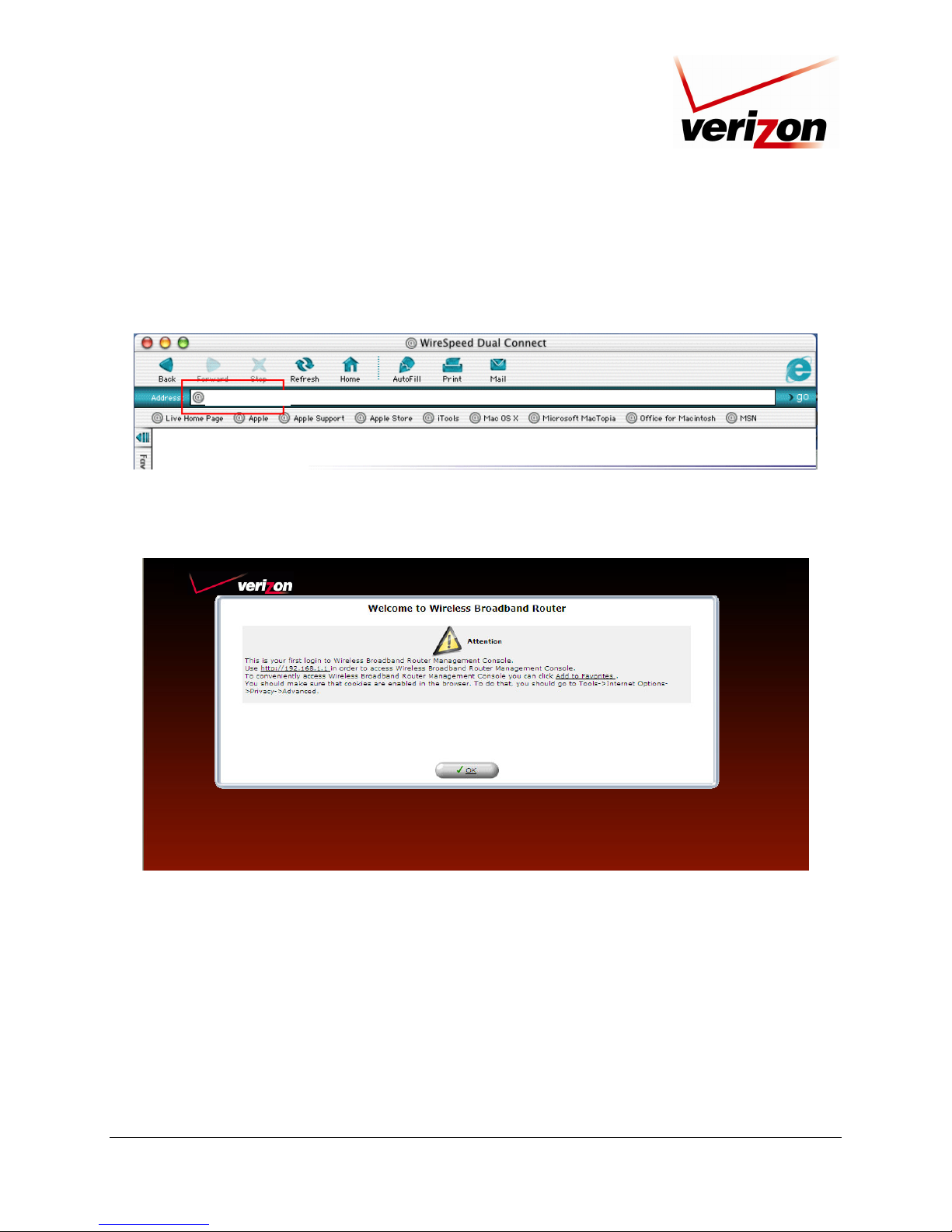
To log on to the Router, start your Web browser, and then type the following IP address in the browser’s address
bar:
http://192.168.1.1
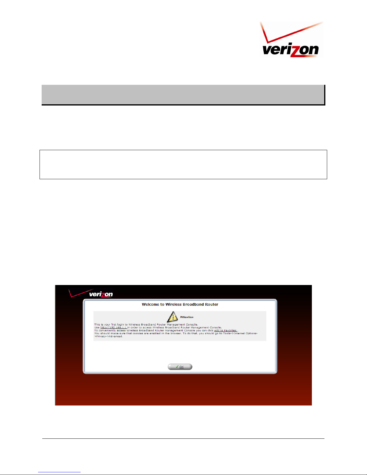
After you type the IP address, press Enter on your keyboard. The following screen will display the message:
This is your first login to the Management Console. Use http://192.168.1.1 in order to access the Router’s
Management Console. To conveniently access the Management Console, you can click Add to Favorites. You
should make sure that cookies are enabled in the browser. To enable cookies, go to Tools->Internet Options>Privacy->Advanced.
Click OK in the Welcome screen.
030-300239 Rev. A 18 March 2008
Page 19
p
Verizon FiOS Router (Model 9100VM)
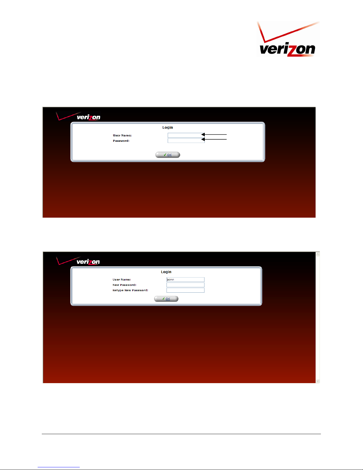
Next, type the default user name (which is
provided. Click OK to continue.
User Guide
admin) and the default password (which is password) in the fields
admin
assword
After you have entered “admin” and “password” in the preceding screen, the following screen will prompt you to
enter a new password. Enter the new password in the fields provided. (If desired, you can use “admin” as the user
name or change this value to the name of your choice.) Then click OK to continue.
030-300239 Rev. A 19 March 2008
Page 20
Verizon FiOS Router (Model 9100VM)
User Guide
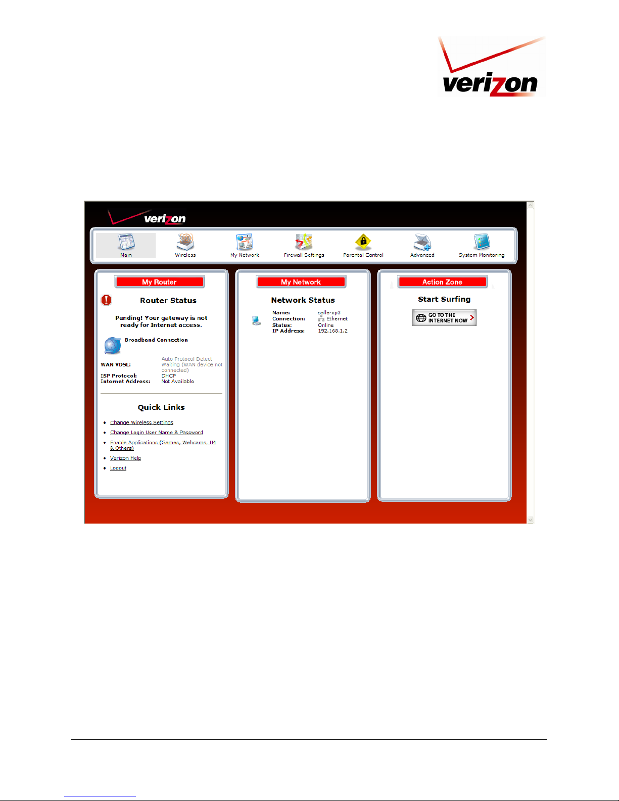
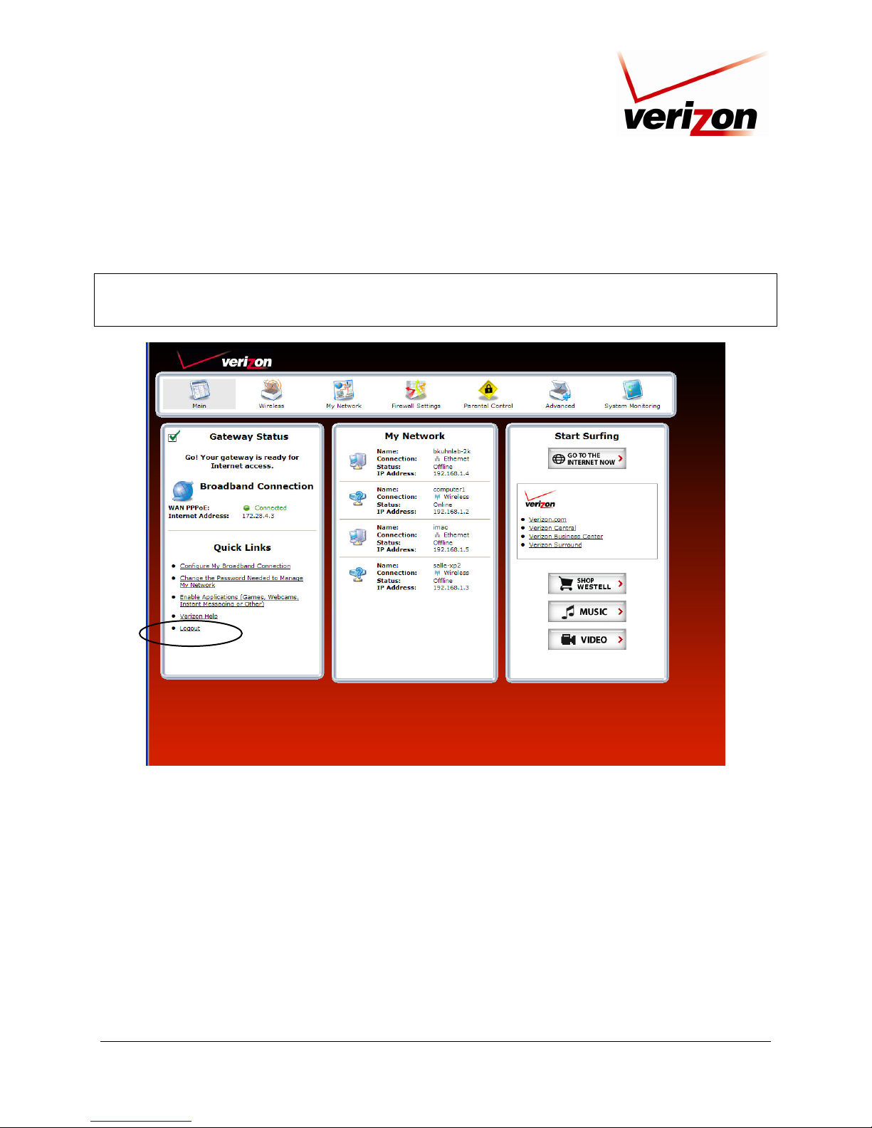
After you have logged on to your Router, the following screen will appear. This is the main page of your Router’s
Web pages, also referred to in this document as the home page. You can access this page by clicking Main in the
navigation menu located across the top of the Router’s Web pages. Details on this page will be explained in the
following sections.
030-300239 Rev. A 20 March 2008
Page 21
Verizon FiOS Router (Model 9100VM)
User Guide
8. CONFIGURING YOUR BROADBAND CONNECTION
To browse the Internet using your Router, you must confirm your VDSL2 connection and establish an Internet
connection with Verizon. The procedures for configuring your Router’s connection settings are explained in this
section.
8.1 Confirming Your VDSL2 Connection
IMPORTANT: You must have active VDSL2 service before the Router can synchronize with Verizon’s equipment.
To determine if the Router has established a VDSL2 link, at the Router’s front panel, check to see if the Router’s
BROADBAND LED is solid green. Solid green indicates that a VDSL2 connection is established. (The
BROADBAND LED may flash while the connection is being established. Please wait a brief moment for the Router
to connect.
After confirming your VDSL2 connection, proceed to section 8.2 to configure your Router’s Internet connection
settings.
8.2 Connecting to the Internet
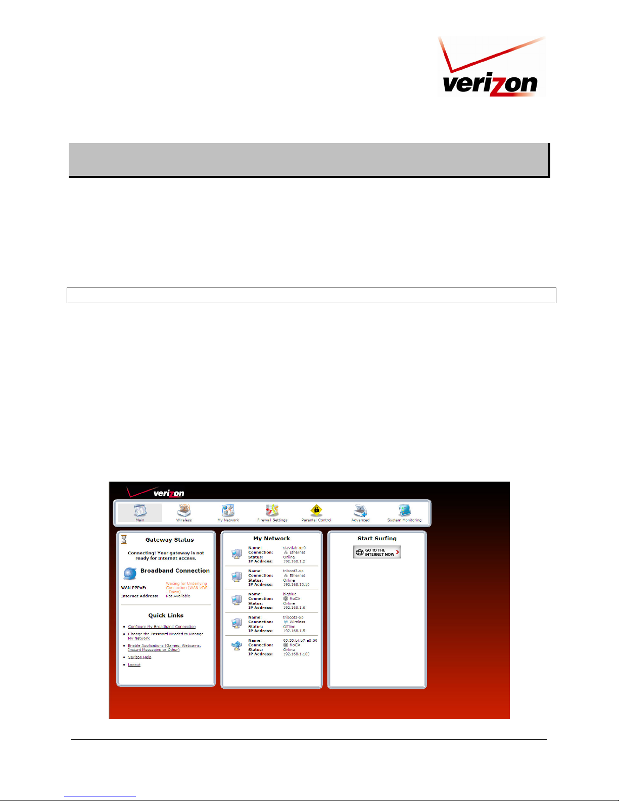
After you have logged on to the Router, the following home page will appear. Use this page to determine the
Router’s Internet connection status. If you do not have an Internet connection, the Internet Address field will
display “Not Available.”
030-300239 Rev. A 21 March 2008
Page 22
Verizon FiOS Router (Model 9100VM)
User Guide
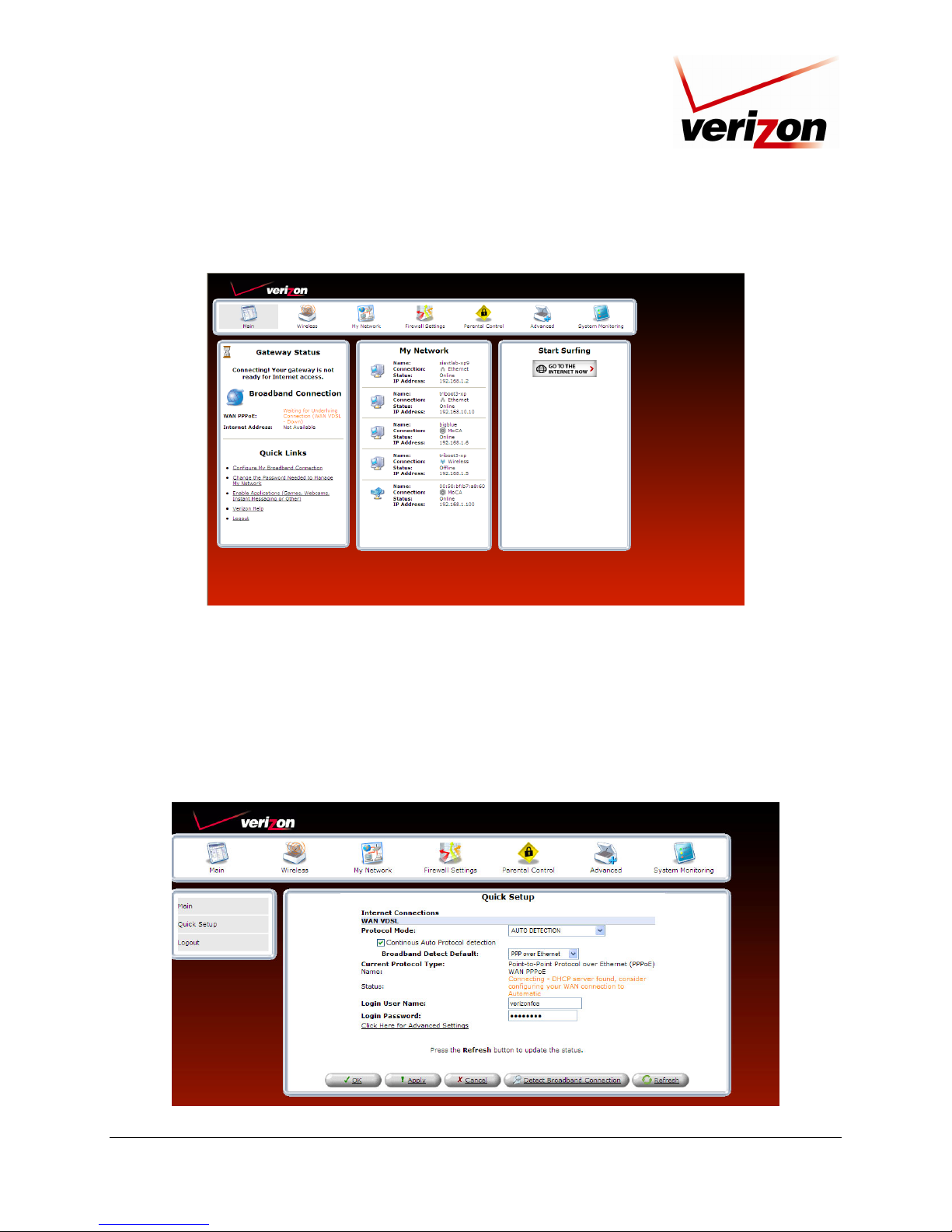
To begin your connection setup, at the home page, go to the Quick Links section, and then click the Configure My
Broadband Connection link.
The following Quick Setup screen will be displayed. At this screen, do the following:
1. From the Broadband Detect Default drop-down list, select Point-to-Point Protocol over Ethernet
(PPPoE).
2. Enter the login user name and login password in the fields provided. (These values are provided by Verizon)
3. Click Apply to save the settings.
Next, click the Click Here for Advanced Settings link to go to the WAN VDSL2 Properties screen.
030-300239 Rev. A 22 March 2008
Page 23
Verizon FiOS Router (Model 9100VM)
User Guide
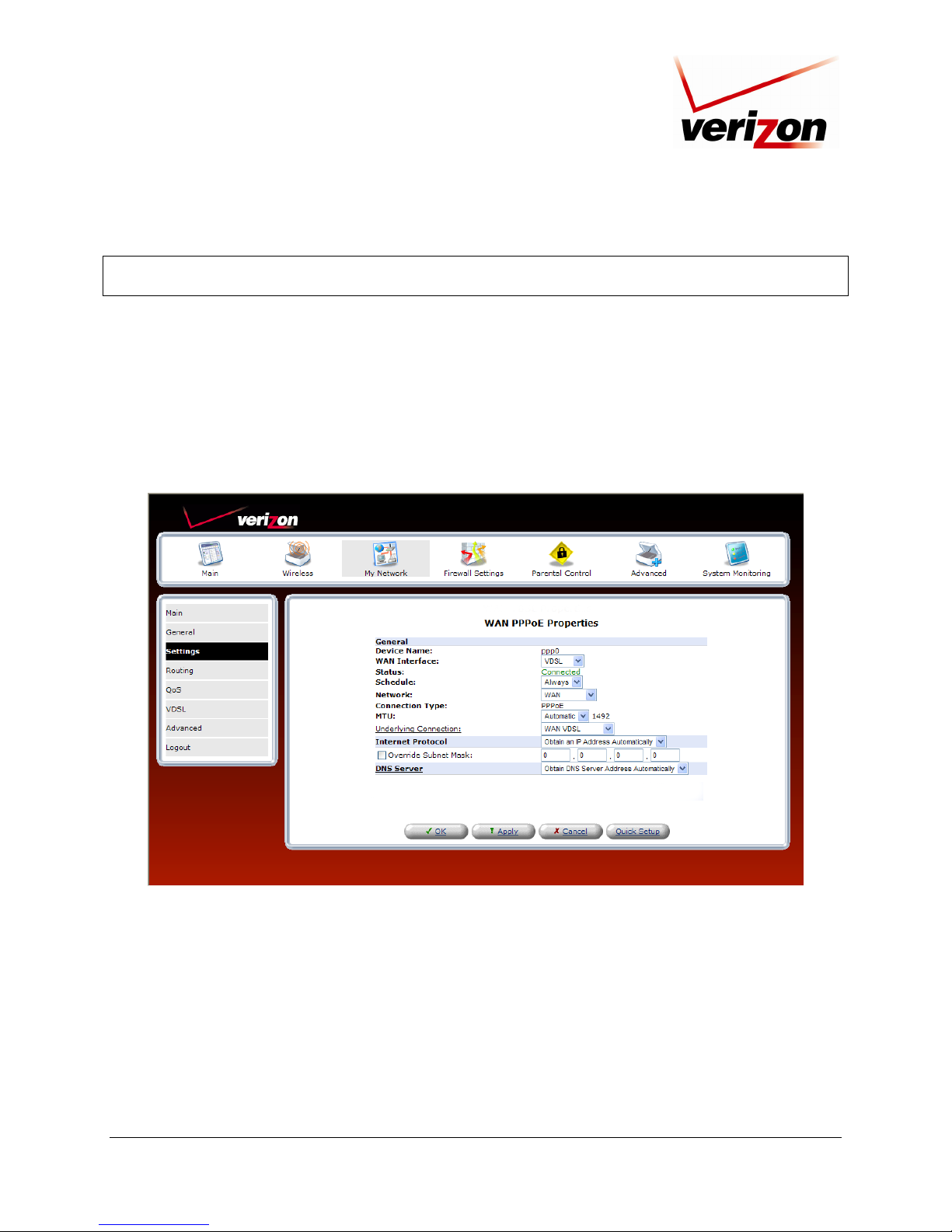
In the WAN PPPoE Properties screen, select Settings in the left submenu.
NOTE: To configure additonal WAN PPPoE properties, select Routing and PPP in the left submenu. If you change
any settings in these screens, click Apply to save the settings.
If you selected Settings in the left submenu, the following screen will appear. Do the following:
1. Select WAN from the Network drop-down list.
2. Select WAN VDSL2 from the Underlying Connection drop-down list
3. Click Apply to save the settings.
After you click Apply, the Status field will display Connected. Next, click Main in the left submenu to return to
the home page.
030-300239 Rev. A 23 March 2008
Page 24
Verizon FiOS Router (Model 9100VM)
User Guide
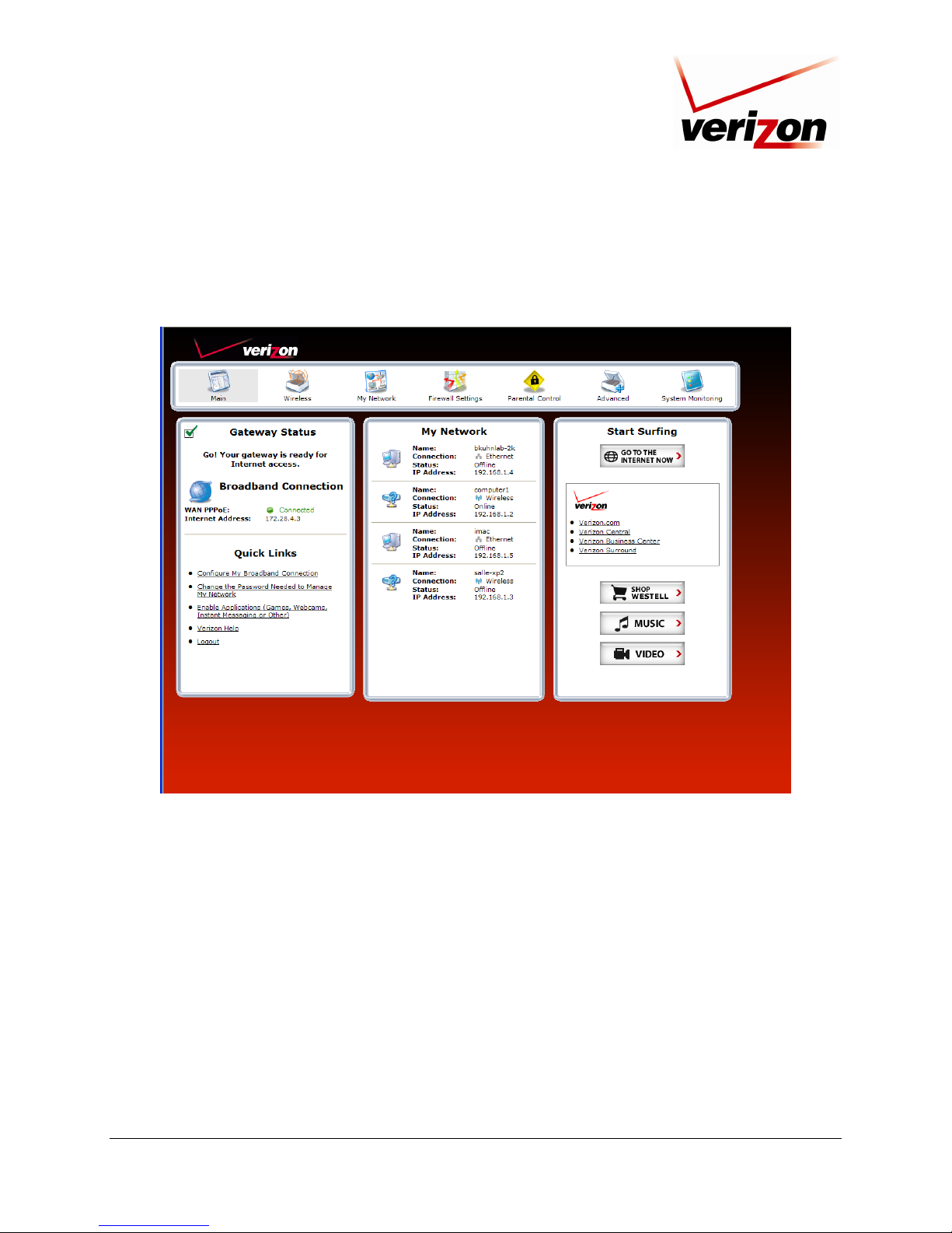
At the home page, view the Gateway Status panel. The message Go! Your gateway is ready for Internet access
should now be displayed. In addition, the Internet Address field will display the WAN IP address of your Router.
Congratulations! You are ready to browse the Internet. To quickly access your default Web page, click GO TO THE
INTERNET NOW.
030-300239 Rev. A 24 March 2008
Page 25
Verizon FiOS Router (Model 9100VM)
User Guide
8.3 Logging Out of the Router’s Web Pages
When you are ready to log out of the Router’s web pages, click the Logout link in any of the Web screens.
NOTE: If you want to close the Router’s Web page, simple click the “X” in the upper-right corner of the window.
Logging out or closing the window does not affect your Internet connection or your VDSL2 connection. However,
you will need to log in again when you are ready to access the Router’s pages.
030-300239 Rev. A 25 March 2008
Page 26
Verizon FiOS Router (Model 9100VM)
User Guide
9. SETTING UP MACINTOSH OS X
This section provides instructions on how to use Macintosh Operating System 10 with the Router. Follow the
instructions in this section to create a new network configuration for Macintosh OS X.
NOTE: Macintosh computers must use the Router’s Ethernet installation. Refer to section 6, “Installing the
Hardware,” for details.
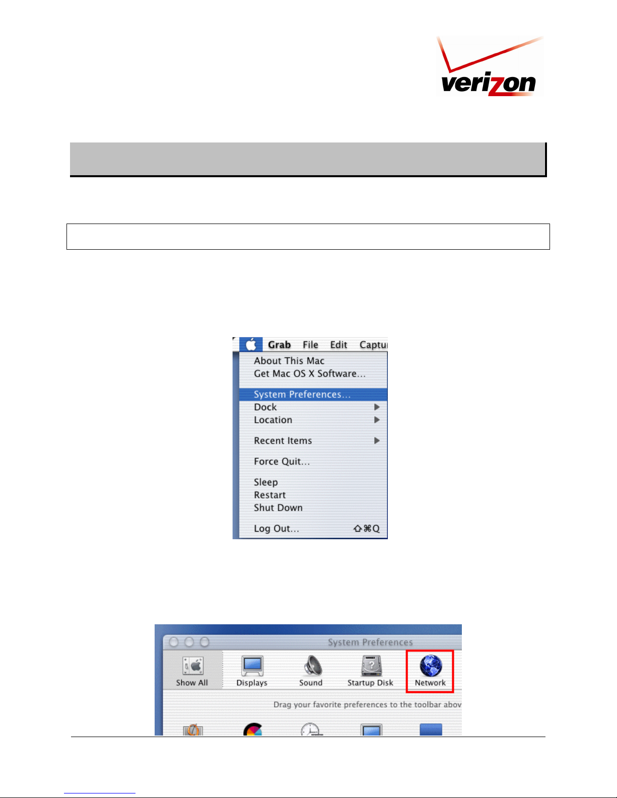
9.1 Opening the System Preference Screen
After you have connected the Router to the Ethernet port of your Macintosh, the screen below will appear. Click the
“Apple” icon in the upper-left corner of the screen and select System Preferences.
9.2 Choosing the Network Preferences
After selecting System Preferences from the previous screen, the following screen will appear. Click the Network
icon.
030-300239 Rev. A 26 March 2008
Page 27
Verizon FiOS Router (Model 9100VM)
User Guide
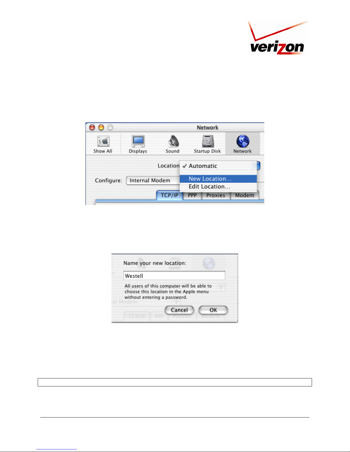
9.3 Creating a New Location
After clicking the Network icon, the Network screen will appear. Select New Location from the Location field.
9.4 Naming the New Location
After selecting New Location in the Network screen, the following screen will appear. In the field labeled
Name your new location:, change the text from “Untitled” to “Westell.” Click OK.
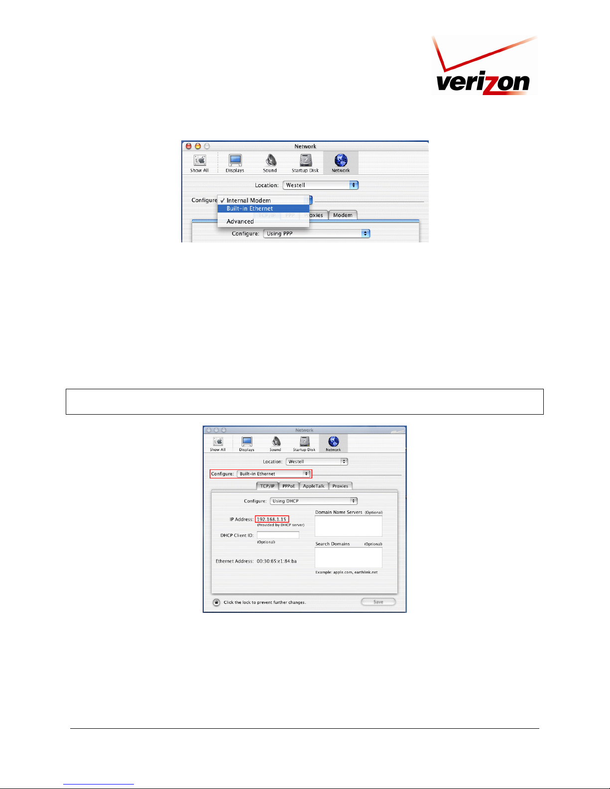
9.5 Selecting the Ethernet Configuration
After clicking OK in the preceding screen, the Network screen will appear. The Network screen shows the settings
for the newly created location. From the Configure field in the Network screen, select Built-in Ethernet. Click
Save to save the settings.
NOTE: Default settings for the Built-in Ethernet configuration are sufficient to operate the Router.
030-300239 Rev. A 27 March 2008
Page 28
Verizon FiOS Router (Model 9100VM)
User Guide
9.6 Checking the IP Connection
To verify that the computer is communicating with the Router, follow the instructions below.
1. Go to the “Apple” icon in the upper-left corner of the screen and select System Preferences.
2. In the System Preferences screen, click the Network icon. The Network screen will appear.
3. In the Configure field in the Network screen, select Built-in Ethernet.
4. View the IP address field. An IP address that begins with 192.168.1 should appear.
NOTE: The Router’s DHCP server provides this IP address. If this IP address is not displayed, check the Router’s
wiring connection to the PC. If necessary, refer to section 6, “Installing the Hardware,” for installation instructions.
030-300239 Rev. A 28 March 2008
Page 29
Verizon FiOS Router (Model 9100VM)
User Guide
9.7 Accessing Your Router
In your Internet Explorer Web browser’s address bar, type http://192.168.1.1, and then press Enter on your
keyboard.
http://192.168.1.1
The Login screen will appear. Please refer to the Login screen in section 7.1 of this User Guide for logon
instructions.
030-300239 Rev. A 29 March 2008
Page 30
Verizon FiOS Router (Model 9100VM)
User Guide
10. BASIC CONFIGURATION
IMPORTANT: The following sections assume that you have active VDSL2 and Internet service.
The Router allows you to make changes to the configurable features such as connection settings, routing
configurations, and firewall settings. The following sections explain each feature and show you how to make
changes to the Router’s settings. The navigation menu displayed at the top of each page allows you to navigate to
the various configuration screens of your Router. Whenever you change settings in your Router, you must click
Apply to allow the changes to take effect in the Router.
NOTE:
1. If you need help, go to the Quick Links section in the home page and then click the Verizon Help link. Clicking
this link takes you to Verizon’s Online Help site where you can find additional information about your VDSL2
Router.
2. If you click OK or Apply in a screen and then experience a delay, you may need to refresh the screen; press the
Refresh button (where applicable) or press F5 on your keyboard.
3. If you want to logout of the Router’s Web page, click the logout link in the home page. Clicking this link does not
affect your Internet connection; it only closes the Router’s Web page. To log in, you will need to enter your
username and password in the Login screen.
To configure the basic settings in your Router, follow the instructions provided in sections 11 through 15.
030-300239 Rev. A 30 March 2008
Page 31

Verizon FiOS Router (Model 9100VM)
User Guide
11. MAIN (HOME PAGE)
After you have logged on to your Router and established a PPP session with Verizon, click Main in the top navigation
menu. The following home page will appear. The home page allows you to view connection information reported by
your Router and to quickly access Internet services provided by Verizon. The following sections discuss each panel in
the Main page. The Main page will be referred to as the home page throughout this User Guide.
030-300239 Rev. A 31 March 2008
Page 32

Verizon FiOS Router (Model 9100VM)
User Guide
11.1 Gateway Status
In the home page, the Gateway Status panel allows you to view the status of your Router’s Internet connection.
Whenever you have an Internet connection, a green check mark is displayed. This signals you to Go! You can now
browse the Internet. In addition, the Router’s connection type and WAN IP address will also be displayed.
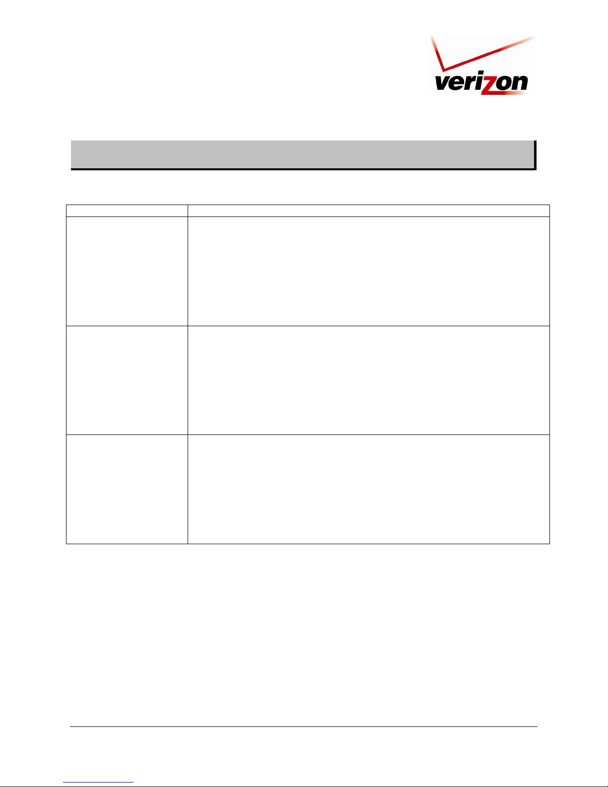
11.2 Quick Links
The Quick Links panel allows access to your broadband connection settings, and provides a link to Help
information related to your Router. The following links are displayed in the Quick Links panel.
Quick Links
Configure My Broadband Connection Click this link to access the Router’s connection settings.
Change the Password Needed to
Manage Network Connections
Enable Applications (Games, Web
Cams, Instant Messaging, other)
Verizon Help Click this link to access Verizon’s Online Help site.
Logout Click this link to log out of the Router’s Web pages.
Click this link to change Administrator permissions, or to set up privileges
for new users and groups on your network.
Click this link to open a tunnel between remote (Internet) computers and a
specific device port inside your local area network (LAN).
11.3 Network Connections
In the home page, the Network Connections panel allows you to view information about devices that are connected
to your network. If your network provides access to shared files, you can access the files by clicking the Access
Shared Files link. The following details are displayed in the Network Connections panel.
Network Connections
Computer Name The ASCII (text) name or MAC address of the device connected to the network.
Connection Type The physical or wireless connection used to interface with your Router.
Status The Internet status of the connected device: Offline or Online.
IP Address The IP address assigned to a device on your network.
11.4 Start Surfing
In the home page, the Start Surfing panel allows quick access to Internet services provided by Verizon. The
following details are displayed in the Start Surfing panel.
NOTE: The links displayed in the Start Surfing panel are specific to the services offered by Verizon and will be
available only after you have established an Internet connection with Verizon.
Start Surfing
Go to the Internet Now Click this button to go to the default page of your Web browser.
Verizon Click the links in this section to access networking services provides by Verizon.
Shop Westell Click this button to go to Westell’s home page.
Music Click this button to go to the Verizon Surround - Music page.
Video Click this button to go to the Verizon Surround - Movies page.
030-300239 Rev. A 32 March 2008
Page 33

Verizon FiOS Router (Model 9100VM)
User Guide
12. WIRELESS
12.1 Wireless Status
If you click Wireless in the top navigation menu and then select Wireless Status in the left submenu, the following
screen will appear. This screen allows you to view details about your wireless connection.
NOTE: If you change the Router’s wireless settings, wireless access to the Router may be interrupted and wireless
stations may require reconfiguration.
030-300239 Rev. A 33 March 2008
Page 34

Verizon FiOS Router (Model 9100VM)
User Guide
12.2 Basic Security Settings
If you select Wireless from the top navigation menu and then select Basic Security Settings in the left submenu, the
following screen will appear. Your Router also functions as a wireless access point for wireless devices. To configure
your wireless settings, enter the appropriate values in the fields provided. Then, click Apply to allow the settings to
take effect. The following table explains the details of this screen.
IMPORTANT:
1. If you are connecting to the Router via a wireless network adapter, the computer’s wireless network adapter must
be configured with the Router’s Service Set ID (SSID); that is, the SSID used in the wireless network adapter
must be identical to the Router’s SSID. The default SSID for the Router is the serial number of the unit (located
below the bar code on the bottom of the unit and also on the shipping carton). Locate and run the utility software
provided with the wireless network adapter, and then enter the identical SSID and WEP encryption security
settings displayed in the Router into the wireless adapter. For privacy, you can change the SSID and security
settings to your desired values. SSIDs are case sensitive and can contain up to 32 alphanumeric characters,
including spaces.
2. In order for every computer on your network to connect to your Router wirelessly, confirm that each computer’s
wireless adapater is using the same security settings that you have configured in the Router’s Basic Security
Settings screen. After you have configured all the settings in this screen, please record the settings for future
reference.
030-300239 Rev. A 34 March 2008
Page 35

Verizon FiOS Router (Model 9100VM)
User Guide
Wireless Settings
Wireless (ON/OFF) By default, the wireless feature is enabled. To completely turn off the wireless networking
feature and the Router’s internal wireless radio, select OFF.
Change SSID Factory Default = 07B406037157
The SSID is the name of your wireless network. This string is case-sensitive and must be
30 characters or less. To connect to the Router, the SSID on a computer’s wireless card
must be identical the SSID on the Router. The Router comes pre-configured with the SSID;
however, you can change the SSID to any name or code you want.
Channel This is the channel of the frequency band at which the Router communicates.
The Router transmits and receives data on this channel. The number of channels to choose
from is pre-programmed into the Router. A computer’s wireless card does not have to be
set to the same channel as the Router; the wireless card can scan all channels and look for a
Router to connect to. (In the United States, use channels 1 through 11).
For better performance, select a channel that is not being used or being used the least by
other wireless devices such as cordless phones or other Routers in the area . If "Automatic"
is selected, the Router will determine the optimal channel to use.
WEP Security Factory Default = OTHER SECURITY
WEP security encrypts the Router's wireless traffic and prevents unauthorized access to the
Router's network. If "OTHER SECURITY" is selected by default, it means that current
030-300239 Rev. A 35 March 2008
Page 36

Verizon FiOS Router (Model 9100VM)
User Guide
wireless security setting is configured using advanced options. If "OTHER SECURITY" is
manually selected on this page, it will be ignored. (See 'Advanced Security Settings' for
additional security options.) Selecting "NO SECURITY" will disable wireless security and
is not recommended.
WEP Key Length A WEP encryption key is used to protect your wireless transmissions. These keys are of
varying lengths. The key can include the numbers 0-9 and letters a,b,c,d,e, and f. The
number of characters must be either 10 (for 64/40 bit encryption) or 26 (for 104 bit
encryption). If this page is used to configure WEP, key 1 will be used as the active key.
You should note this value as you will have to enter it into each device which is connecting
wirelessly
WEP Key This is the actual security key value. You should note this value as you will have to enter it
into each device which is connecting wirelessly.
Number of Required
Digits
Configure Wireless Client
Settings to match Router’s
settings
This field indicates how many more characters are needed to complete the security key.
The security key is not complete unless this counter indicates 0.
For wireless clients, such as computers and other devices with wireless cards to establish a
wireless connection to this Router, the clients' settings, especially the SSID, channel,
wireless mode, and security (i.e., WEP) settings must match the Router's settings as
summarized in the table. If channel is set to Automatic, the Router will determine the
optimal channel to use. (If settings, particularly if using advance security options, are
changed in other or "Advanced" sections, the sections where the changes were made must
be consulted for reference.)
030-300239 Rev. A 36 March 2008
Page 37

Verizon FiOS Router (Model 9100VM)
User Guide
12.3 Advanced Security Settings
If you select Wireless from the top navigation menu and then select Advanced Security Settings in the left
submenu, the following screen will appear. Generally, most owners of the Router will not need to modify these
wireless options.
From this menu, you can change your wireless security level by selecting the desired choice: WEP, WEP + 802.11x,
or Wireless Protected Access (WPA). You can also enable/disable the SSID broadcast feature fo the product.
If you want to limit connected wireles dievces only to the 802.11g (54Mbps) standard, chose the 802.11 b/g mode
link and select the desired mode.
For full access to all wireless and secuity settings one on page, click on the Other Advanced Wireless Options
link.
030-300239 Rev. A 37 March 2008
Page 38

Verizon FiOS Router (Model 9100VM)
User Guide
12.3.1 SSID Broadcast
If you clicked the SSID Broadcast link, the following screen will appear. By disabling the SSID broadcast, your
Router will no longer send out messages indicating that it is in place. Disabling the SSID broadcast does not disable
the wireless interface and clients configured with the correct SSID and wireless security key (when enabled) will
still be able to connect.
030-300239 Rev. A 38 March 2008
Page 39

Verizon FiOS Router (Model 9100VM)
User Guide
12.3.2 Wireless MAC Authentication
If you clicked the Wireless MAC Authenticaton link, the following screen will appear. Set up your MAC Filtering
settings, and then click Apply to save the settings.
For example, if you select “Allow” from the MAC filtering Mode drop-down list, this option will allow only the
devices whose MAC Addresses are active in the list to connect to the Router. Next, click the New MAC Address
link to add the desired MAC address.
030-300239 Rev. A 39 March 2008
Page 40

Verizon FiOS Router (Model 9100VM)
User Guide
If you clicked New MAC Address, the following screen will appear. Enter the MAC address of the device that you
want to allow access to the Router. Then, click OK to continue.
NOTE: If you enter a duplicate MAC address, the following screen will appear. Enter a valid MAC address and
click OK to continue.
030-300239 Rev. A 40 March 2008
Page 41

Verizon FiOS Router (Model 9100VM)
User Guide
After you have entered a valid MAC address and clicked OK, the following screen will appear. Click Apply to save
the settings. From this screen, you may add additional MAC address to the list or edit/delete existing MAC address.
If you make any changes, be sure to click Apply to save the changes.
After you have entered a valid MAC address, the following Advanced Security Settings screen will display all the
MAC addresses that have been added to the MAC filtering table. Be sure to select the desired option from the MAC
Filtering Mode drop-down list. Then, click Apply to allow the settings to take effect in the Router.
To edit a MAC address, click the pencil icon next to the address you want to edit. To delete a MAC address, click the
“X” icon next to the address you want to delete. To add a new MAC address, click the plus icon, or click the New
MAC Address link.
030-300239 Rev. A 41 March 2008
Page 42
Verizon FiOS Router (Model 9100VM)
User Guide
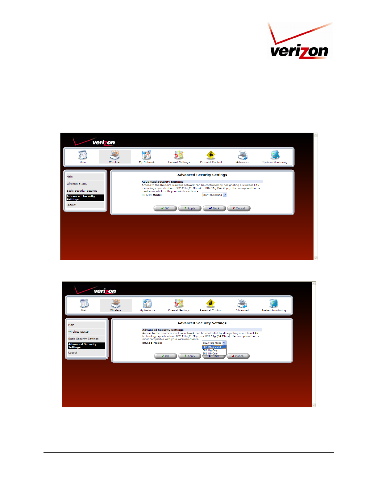
12.3.3 802.11b/g Mode
If you clicked the 802.11b/g Mode link, the following screen will appear. Access to the Router’s wireless network
can be controlled by designating a wireless LAN technology specification 802.11b (11 Mbps) or 802.11g (54 Mbps).
Use an option that is most compatible with your wireless clients.
Select the desired mode from the drop-down list, and then click Apply to save the settings.
030-300239 Rev. A 42 March 2008
Page 43

Verizon FiOS Router (Model 9100VM)
User Guide
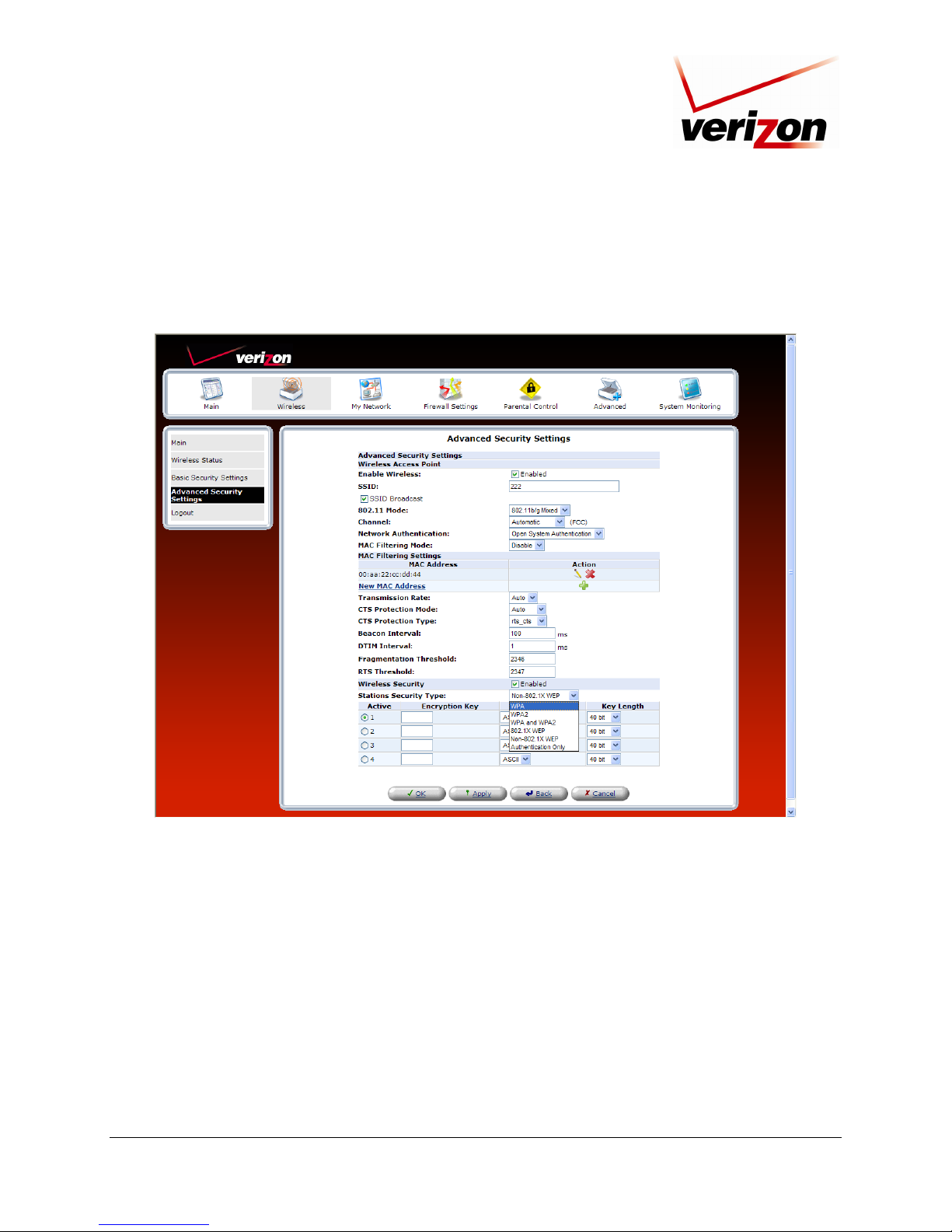
12.3.4 Other Advanced Wireless Options
If you clicked the Other Advanced Wireless Options link, the following screen will appear. Click Yes to proceed.
The following screen will appear. Enter the desired values, and then click Apply to save the settings. The following
table explains the details of this screen.
030-300239 Rev. A 43 March 2008
Page 44

Verizon FiOS Router (Model 9100VM)
User Guide
Advanced Security Settings
Wireless Access Point The Router also functions as a wireless access point for wireless devices.
Enable Wireless By default, the wireless feature is enabled. To disable this feature, clear the check box.
SSID Factory Default = 07B406037157
The SSID is the name of your wireless network. This string is case-sensitive and must be
30 characters or less. To connect to the Router, the SSID on a computer’s wireless card
must be identical the SSID on the Router. The Router comes pre-configured with the SSID;
however, you can change the SSID to any name or code you want.
SSID Broadcast Select this check box to enable SSID (a check mark will appear in the box).
When this box is cleared, the Router will not broadcast its SSID.
When SSID Broadcast is enabled, any computer or wireless device using the SSID of
“ANY” can see the Router. To prevent this from happening, click the Disable option
button. This will disable SSID Broadcast so that only the wireless devices that are
configured with your SSID can access your Router.
802.11 Mode Allows you to limit access to your Router based on technology type.
11b only: Communication with the Router is limited to 802.11b
11g only: Communication with the Router is limited to 802.11g
802.11 b/g Mixed: Computers using 802.11b or 802.11g rates can communicate with the
Router.
Channel This is the channel of the frequency band at which the Router communicates.
The Router transmits and receives data on this channel. The number of channels to choose
from is pre-programmed into the Router. A computer’s wireless card does not have to be
set to the same channel as the Router; the wireless card can scan all channels and look for a
Router to connect to. (In the United States, use channels 1 through 11).
Network Authentication Open System Authentication: If Open System authentication is selected, this will allow any
station to associate with the wireless network, but only stations with a valid WEP key can
send or receive data from the Router.
Shared Key Authentication: If Shared Key Authentication is selected, a station must
authenticate with the Router (using the WEP key) before it can connect to the Router’s
wireless network.
Both: If “Both” is selected, the Router will allow both Open System and Shared Key
Authentication to be used.
MAC Filter Mode Disable: If Disable is selected, MAC Filtering Mode will be deactivated.
Allow: If Allow is selected, the Router will allow only the devices that are configured in
the MAC filter table.
Deny: If Deny is selected, the Router will deny all devices that are configured in the MAC
filter table.
MAC Filtering Settings Click this link to add a MAC address to the MAC filtering list. Details on this feature are
discussed later in this section.
Transmission Rate Selecting a transmission rate allows you to adjust the bit rate of the Router’s wireless
transmissions. Select a transmission rate from the drop-down list, or select Auto to allow
the Router to automatically select the best transmission rate.
CTS Protection Mode Clear to Send (CTS) allows the 802.11 b/g networks to operate a maximum efficiency.
Auto: Select Auto to activate CTS.
None: Select None to deactivate CTS.
Always: Select Always to allow CTS to always be activated.
CTS Protection Type CTS (Clear to Send) protection mode allows mixed 802.11b/g networks to operate at
maximum efficiency.
RTS (Request to Send) controls what size data packet the low level RF protocol issues to
an RTS packet.
030-300239 Rev. A 44 March 2008
Page 45

Verizon FiOS Router (Model 9100VM)
User Guide
Select cts_only to activate this feature.
Select cts_rts to activate this feature.
Beacon Interval
(in milliseconds)
Enter the beacon interval value.
The beacon interval is the time between beacon frame transmissions. Beacons are
transmitted by the Router to help identify wireless networks. Beacons contain rate and
capability information. Beacons received by stations can be used to identify the wireless
access points in the area.
DTIM Interval
(in milliseconds)
Enter the DTIM (Delivery Traffic Indication Message) interval value. A DTIM is a
countdown mechanism for the Router. It informs wireless network clients of the next
window for listening to broadcast and multicast messages.
Fragmentation Threshold Setting the fragmentation threshold can increase the reliability of frame transmissions on
the wireless network. Any MAC Service Data Unit (MSDU) or MAC Protocol Data Unit
(MPDU) larger than this value will be fragmented into an MPDU of the specified size.
RTS Threshold Enter the RTS (Request to Send) threshold. This setting controls what size data packet the
low level RF protocol issues to an RTS packet.
RTS/CTS handshaking will be performed for any data or management MPDU containing a
number of bytes greater than the threshold. If this value is larger than the MSDU size
(typically set by the fragmentation threshold), no handshaking will be performed. A value
of zero will enable handshaking for all MPDUs.
Wireless Security When this feature is enabled (the box contains a check mark), wireless security is activated,
and the security type can be configured.
When the box is clear, wireless security is deactivated. By factory default, Wireless
Security is disabled.
Stations Security Type Set the type of security for the Router’s wireless network. Choose from the following
options: WPA, WPA2, WPA and WPA2, 802.1x WEP, Non-802.1x WEP, Authentication
Only. Details on these options are discussed later in this section.
Authentication Method This is the authentication method used with the security type.
030-300239 Rev. A 45 March 2008
Page 46
Verizon FiOS Router (Model 9100VM)
User Guide
12.3.5 Configuring the Stations Security Type
To configure the Router’s wireless security type for the wireless network, in the Advanced Security Settings
screen, select an option from the Stations Security Type drop-down list. The following sections describe each
security type.
030-300239 Rev. A 46 March 2008
Page 47

Verizon FiOS Router (Model 9100VM)
User Guide
12.3.5.1 WPA (Wi-Fi Protected Access v.1)
If you select WPA in the Stations Security Type drop-down list, the following screen will appear. WPA allows you
to enable a pre-shared key for your home network or for advanced security for an enterprise network. This option
allows stations that support WPA v.1 to connect to the Router.
WPA Wireless Security
Wireless Security Factory Default = Enabled
When this feature is enabled (the box contains a check mark), wireless security in activated.
If the box is cleared, wireless security will be deactivated.
Stations Security Type Factory Default = WPA
Set the type of security for the Router’s wireless network. Choose from the following options:
Details on these options are discussed later in this section.
WPA – Allows stations that support WPA v.1 to connect to the Router.
WPA2 – Allows stations that support WPA v.2 to connect to the Router.
WPA and WPA2 – Allows stations that support WPA and WPA2 to connect to the Router.
802.1x WEP – Allows stations that support 802.1x WEP to connect to the Router.
Non-802.1x WEP – Allows stations that support Non-802.1x WEP to connect to the Router.
Authentication Only – Allows stations that support Authentication Only to connect to the Router.
Authentication Method Factory Default = Personal (Pre-Shared Key)
Pre-Shared Key – WPA stations share a pre-shared key (string format) with the Router and do
not authenticate with the RADIUS server.
802.1x – WPA stations authenticate with the RADIUS server using EAP-TLS over 802.1x, a
standard for passing extensible authentication protocol (EAP) for authentication purposes. EAP
is used to communicate authentication information between the supplicant and the authentication
server. With 802.1x, EAP messages are packaged in Ethernet frames, rather than using and PPP.
Pre-Authentication Factory Default = Disabled
To Enable this feature, click the box (a check mark will appear in the box).
030-300239 Rev. A 47 March 2008
Page 48

Verizon FiOS Router (Model 9100VM)
User Guide
WPA Pre-Shared Key The WPA key can be either 8 to 63 text (ASCII) characters or 64 hexadecimal (Hex) characters.
The only allowable hexadecimal characters are: A-F and 0-9.
Group Key Update
Interval (in seconds)
The number of seconds between rekeying the WPA group key. A value of zero means that
rekeying is disabled.
After you have selected the security type, select the desired authentication method from the Authentication Method
drop-down list.
12.3.5.1.1 Authentication Method—Pre-Shared Key
If you select Pre-Shared key as the authentication method for WPA, the following screen will appear. Configuring
Pre-Shared Key in the Router allows devices that know the pre-shared key to connect to the Router.
NOTE: A WPA pre-shared key is treated as either a string of text (ASCII) characters or a set of
hexadecimal (Hex) characters. The key can be either 8 to 63 text (ASCII) characters or 64 hexadecimal
(Hex) characters. The only allowable hexadecimal characters are: 0-9 and A-F.
To configure the WPA Pre-Shared Key, do the following:
1. Select the string type (ASCII or HEX) in the Pre-Shared Key drop-down list.
2. Enter the desired pre-shared key values in the field provided.
3. Select the desired option from the Encryptoin Algorithm drop-down list.
• TKIP: Select this option to enable the Temporal Key Integrity Protocol for data encryption.
030-300239 Rev. A 48 March 2008
Page 49

Verizon FiOS Router (Model 9100VM)
User Guide
• AES: Select this option to enable the Advanced Encryption Standard for data encryption.
• TKIP and AES: Select this option to enable the Router to accept TKIP and AES encryption.
4. Enter the desired Group Key Update Interval, and confirm that the adjacent box contains a check mark. (By
factory default, Group Key Interval is enabled for 900 seconds.)
5. Click OK to save the wireless settings in the Router.
12.3.5.1.2 Authentication Method—802.1x
If you select 802.1x as the authentication method for WPA, the following screen will appear. Configuring 802.1x
allows devices that support 802.1x to connect to the Router.
To configure WPA authentication for 802.1x, do the following:
1. Select the desired option from the Encryptoin Algorithm drop-down list.
• TKIP: Select this option to enable the Temporal Key Integrity Protocol for data encryption.
• AES: Select this option to enable the Advanced Encryption Standard for data encryption.
• TKIP and AES: Select this option to enable the Router to accept either TKIP or AES encryption.
2. Enter the desired Group Key Update Interval, and confirm that the box contains a check mark. (By factory
default, Group Key Interval is enabled for 900 seconds.)
3. Configure the Radius Server:
a. Enter the Radius Server IP address in the fields provided.
030-300239 Rev. A 49 March 2008
Page 50

Verizon FiOS Router (Model 9100VM)
b. Enter the desired Server Port value.
c. Enter the Shared Secret.
4. Click OK to save the wireless settings in the Router.
User Guide
030-300239 Rev. A 50 March 2008
Page 51
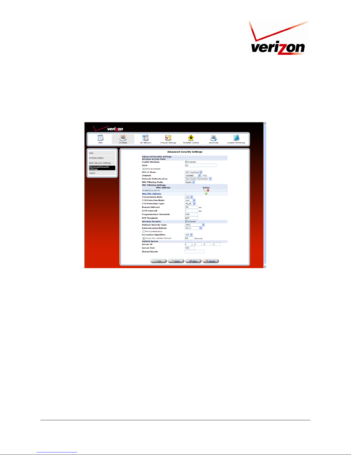
Verizon FiOS Router (Model 9100VM)
User Guide
12.3.5.2 WPA2 (Wi-Fi Protected Access v. 2)
If you select WPA2 in the Stations Security Type drop-down list, the following screen will appear. This option
allows stations that support WPA v.2 to connect to the Router. The configuration settings for WPA2 are similar to
the settings in WPA. Please refer to section 12.3.5.1 for instructions on configuring WPA2.
030-300239 Rev. A 51 March 2008
Page 52

Verizon FiOS Router (Model 9100VM)
User Guide
12.3.5.3 WPA and WPA2
If you select WPA2 and WPA2 in the Stations Security Type drop-down list, the following screen will appear.
This option allows stations that support both WPA v.1 and WPA v.2 to connect to the Router. The configuration
settings for this feature are similar to the settings in WPA. Please refer to section 12.3.5.1 for instructions on
configuring WPA and WPA2.
030-300239 Rev. A 52 March 2008
Page 53

Verizon FiOS Router (Model 9100VM)
User Guide
12.3.5.4 802.1x WEP
If you select 802.1x WEP in the Stations Security Type drop-down list, the following screen will appear. The
802.1x WEP feature allows you to enable WEP keys for wireless security. In addition, 802.1x WEP security uses a
Remove Authentication Dial-in Service (RADIUS) server for authentication purposes. The server must be physically
connected to the Router. The Router’s card supports 40-bit or 104-bit WEP encryption. If 802.1x WEP is used, any
station can connect to the Router as long as its SSID and WEP key values match the Router’s values.
NOTE: Client PCs can use any Wireless 802.11b/g card to communicate with the Router. By default your Router is
configured (enabled) for 802.1X WEP (Wired Equivalent Privacy) security. Whenever, WEP is configured, the PC’s
wireless card must use the same WEP security code type as the one provided in Router. The WEP security code is
located on a label on the bottom of the Router. Always check that your PC’s wireless adapter is configured properly
for whichever network setting you use: WEP or WPA. You can configure the settings in the advanced properties of
the PC’s wireless network adapter.
030-300239 Rev. A 53 March 2008
Page 54

Verizon FiOS Router (Model 9100VM)
User Guide
12.3.5.4.1 Configuring Automatic WEP Encryption Keys
The 802.1x WEP security protocol uses port control with dynamically changing encryption keys automatically
updated over the network. To configure 802.1x WEP to generate keys automatically, do the following:
1. Select the Generate Keys Automatically check box if you want the Router to automataically create the WEP
security keys. A check mark will appear in the box, and the Encryption Key table will be removed from the screen.
NOTE: Disable (clear) the Generation Keys Automatically check box to allow 802.1x-MD5 stations to
connect to the Router
2. Enter the desired Group Key Update Interval, and confirm that the box contains a check mark. (By factory
default, Group Key Interval is enabled for 900 seconds.)
3. Configure the Radius Server:
a. Enter the Radius Server IP address in the fields provided.
b. Enter the desired Server Port value.
c. Enter the Shared Secret.
4. Click OK to save the wireless settings in the Router.
12.3.5.4.2 Configuring Manual WEP Encryption Keys
To configure 802.1x WEP with manual encryption keys, do the following:
1. Clear the Generate Keys Automatically check box. The Key Encryption table will appear in the screen.
NOTE: Disable (clear) the Generation Keys Automatically check box to allow 802.1x-MD5 stations to
connect to the Router.
2. At the Key Encryption table, select a key (1 through 4) that you want to activate.
3. Enter the desired encryption key.
NOTE: A WEP encryption key is treated as either a string of text (ASCII) characters or a set of
hexadecimal (Hex) characters. The number of text characters must be either 5 (for 40 bit encryption) or 13
(for 104 bit encryption). The number of Hex characters must be either 10 (for 40 bit encryption) or 26 (for
104 bit encryption). The only allowable hexadecimal characters are: A-F and 0-9.
4. Select the Entry Method (ASCII or Hex) from the drop-down list.
5. Select the Key Length (40 bit or 104 bit) from the drop-down list.
6. Enter the desired Group Key Update Interval, and confirm that the box contains a check mark. (By factory
default, Group Key Interval is enabled for 900 seconds.)
7. Configure the Radius Server by doing the following:
a. Enter the Radius Server IP address in the fields provided.
b. Enter the desired Server Port value.
c. Enter the Shared Secret.
8. Click OK to save the wireless settings in the Router.
030-300239 Rev. A 54 March 2008
Page 55

Verizon FiOS Router (Model 9100VM)
User Guide
12.3.5.5 Non-802.1x WEP
If you select Non-802.1x WEP in the Stations Security Type drop-down list, the following screen will appear. The
Non-802.1x WEP feature allows you to enable a WEP key for wireless security without using a RADIUS server.
The Router’s card supports 40-bit or 104-bit WEP encryption. Whenever Non-802.1x WEP is used, any station can
connect to the Router as long as its SSID and WEP key values match the Router’s values.
To configure the Router for Non-802.1x WEP, do the following:
1. At the Key Encryption table, select a key (1 through 4) that you want to activate.
2. Enter the desired encryption key.
NOTE: A WEP encryption key is treated as either a string of text (ASCII) characters or a set of hexadecimal
(Hex) characters. The number of text characters must be either 5 (for 40-bit encryption) or 13 (for 104-bit
encryption). The number of Hex characters must be either 10 (for 40-bit encryption) or 26 (for 104-bit
encryption). The only allowable hexadecimal characters are: A-F and 0-9.
3. Select the Entry Method (ASCII or Hex) from the drop-down list.
4. Select the Key Length (40 bit or 104 bit) from the drop-down list.
5. Click OK to save the wireless settings in the Router.
030-300239 Rev. A 55 March 2008
Page 56

Verizon FiOS Router (Model 9100VM)
User Guide
12.3.5.6 Authentication Only
If you select Authentication Only in the Stations Security Type drop-down list, the following screen will appear.
This feature allows you to enable wireless security in your Router without using encryption keys or a RADIUS
server. However, a station’s SSID must match the Router’s SSID in order to connect to the Router.
030-300239 Rev. A 56 March 2008
Page 57

Verizon FiOS Router (Model 9100VM)
User Guide
13. MY NETWORK
This section discusses details about your Router’s network connections.
13.1 Network Status
To view your Router’s network settings, from the top navigation menu, select Network Connections. Next, click
Network Status in the submenu at the left of the screen. The following screen will appear. This screen displays
information about the devices connected to your local area network (LAN).
Network Connections
Name The name of the device.
Type The type of device connected to the network.
The interface used to connect to the Router.
Ethernet: Displays the number of devices that are connected to the Router via Ethernet
Connection
Status The status of the Inernet connection.
IP Address The IP address assigned to the computer.
IP Address Source The method by which the computer receives its IP address.
MAC Address
Connected Devices
Delete All Devices Click this link to delete all devices from your network.
Scan for New Devices
030-300239 Rev. A 57 March 2008
10/100 BaseT connection.
Wireless: Displays the number of devices that are connected to the Router wirelessly.
Note: If you have computers on your network that are not being displayed, check the
firewall setting on the PCs to ensure that the firewall is disabled.
The Media Access Controller; the hardware address assigned to the deviced by the
manufacturer.
The interface used to connect the device to the Router, and the devices connected.
Ethernet: Displays the number of devices that are connected to the Router via Ethernet
10/100 BaseT connection.
Wireless: Displays the number of devices that are connected to the Router wirelessly.
Note: If you have computers on your network that are not being displayed, check the
firewall setting on the PCs to ensure that the firewall is disabled.
Click this link to allow the Router to scan the network for new devices that may have
recently connected to the network.
Page 58

Verizon FiOS Router (Model 9100VM)
User Guide
13.1.1 Website Blocking
In the Network Status page, click the Website Blocking link. You can configure your Router to restrict access to
certain websites. Click the New Entry link.
The following screen will appear. Enter the URL of the desired site in the Restricted Website field. Then select the
local host device to which you want to apply this restriction, and then a schedule for the restriction. Click OK to
save the settings.
030-300239 Rev. A 58 March 2008
Page 59

Verizon FiOS Router (Model 9100VM)
User Guide
If you select User Defined from the Schedule drop-down list, the following screen will appear. Click the New Time
Segment Entry link to set up a time for the restriction.
The following screen allows you to enter the desired time segment. Click the New Hours Range Entry link to add
the time values to the entry.
030-300239 Rev. A 59 March 2008
Page 60

Verizon FiOS Router (Model 9100VM)
After you have entered the desired time values, click OK to save the settings.
User Guide
If you have set up time values and clicked OK, the following screen will appear. Next, select the desired Days of
Week values and click OK.
030-300239 Rev. A 60 March 2008
Page 61

Verizon FiOS Router (Model 9100VM)
User Guide
After you have set up the Hours Range and Days of Week values and clicked OK, the following screen will appear.
If desired, you can enter a name for this schedule rule in the Name field. This screen shows that rules have been
added to the Time Segments table. To add additional schedule rules to your Router, repeat the preceding
instructions. Click OK to continue.
If you clicked OK, the following screen will appear. Enter the website to which you want to restrict access, and then
click OK.
If you clicked OK in the preceding screen, the following screen will appear. To edit an entry, click the pencil icon.
030-300239 Rev. A 61 March 2008
Page 62

Verizon FiOS Router (Model 9100VM)
User Guide
13.1.2 Block Internet Services
In the Network Status page, click the Block Internet Services link. The following Access Control screen will
appear. This feature allows you to block specific computers within the local network (or even the entire network)
from accessing certain services on the Internet. For example, one computer can be prohibited from surfing the
Internet, another computer from transferring files using FTP, and the whole network from receiving incoming email.
To configure Access Control, click the New Entry link.
If you clicked New Entry, the following screen will appear. Enter the desired values in this screen, and then click
OK to save the settings.
030-300239 Rev. A 62 March 2008
Page 63

Verizon FiOS Router (Model 9100VM)
13.1.2.1 Selecting an Address
From the Address drop-down list, select the desired computer for which you want to apply access.
User Guide
After you have selected a computer, the following screen will appear. Proceed to section 13.1.2.2 to select a
protocol.
030-300239 Rev. A 63 March 2008
Page 64

Verizon FiOS Router (Model 9100VM)
User Guide
13.1.2.2 Selecting a Protocol
From the Protocols drop-down list, select the desired option that you want to prohibit the computer from using. To
reply an html page to the blocked client, click the check box (a check mark will appear in the box). To disable this
feature click to clear the check box.
After you have selected the protocol, the following screen will appear. Proceed to section 13.1.2.3 to configure a
schedule rule.
030-300239 Rev. A 64 March 2008
Page 65

Verizon FiOS Router (Model 9100VM)
13.1.2.3 Configuring a Schedule Rule
Select the desired schedule from the Schedule drop-down list.
User Guide
For example, if you selected User Defined from the Schedule drop-down list, the following screen will appear.
Click the desired Rule Activity Settings option button, and then select the New Time Segment Entry link.
030-300239 Rev. A 65 March 2008
Page 66

Verizon FiOS Router (Model 9100VM)
User Guide
If you clicked New Time Segment Entry, the following screen will appear. Click the New Hours Range Entry
link.
If you clicked New Hours Range Entry, the following screen will appear. Enter the desired start time and end time
values in the fields provided, and then click OK to continue.
030-300239 Rev. A 66 March 2008
Page 67

Verizon FiOS Router (Model 9100VM)
User Guide
If you clicked OK the following screen will appear. Next, select the desired Days of Week values and click OK.
After you have set up the Hours Range and Days of Week values and clicked OK, the following screen will appear.
If desired, you can enter a name for this schedule rule in the Name field. This screen shows that rules have been
added to the Time Segments table. To add additional schedule rules to your Router, repeat the preceding
instructions. Click OK to continue.
030-300239 Rev. A 67 March 2008
Page 68

Verizon FiOS Router (Model 9100VM)
User Guide
13.1.2.4 Completing the Access Control Rule Configuration
If you clicked OK in the preceding Edit Scheduler Rule screen, the following screen will appear. Click OK to save
the settings.
If you clicked OK, the following screen will appear. The Router is attempting to resolve the configuration. Click
Resolve Now to continue.
030-300239 Rev. A 68 March 2008
Page 69

Verizon FiOS Router (Model 9100VM)
User Guide
If you clicked Resolve Now, the following screen will appear. The rule has been added to the list of security rules.
To disable the security rule for an entry, click the adjacent check box, and then click Apply. To add additional
access control rules, click the New Entry link.
030-300239 Rev. A 69 March 2008
Page 70

Verizon FiOS Router (Model 9100VM)
User Guide
13.1.3 Access Shared Files
In the Network Status page, click the Access Shared Files link to access files from a device on your local network.
(The device from which you will access files must have file sharing enabled.) If the device has a firewall turned on,
you will not be able to access shared files from the device.
030-300239 Rev. A 70 March 2008
Page 71

Verizon FiOS Router (Model 9100VM)
User Guide
13.1.4 View Device Details
In the Network Status page, click the View Device Details link. The following screen will appear. Click Refresh to
refresh the details on this screen. After you have finished viewing this screen, click OK to return to the Network
Status page.
030-300239 Rev. A 71 March 2008
Page 72

Verizon FiOS Router (Model 9100VM)
User Guide
13.1.5 Enable Application
In the Network Status page, click the Enable Application link to set up applications for your service profile, such
as port forwarding services. This feature enables applications (Games, Webcams, IM & Others) by opening a tunnel
between remote (Internet) computers and a specific device port inside your local area network (LAN). Details on
this screen are discussed later in section 14.3, “Port Forwarding.”
030-300239 Rev. A 72 March 2008
Page 73

Verizon FiOS Router (Model 9100VM)
User Guide
13.1.6 Rename Device
In the Network Status page, click the Rename Device link to rename a device on your network. In the following
screen, type the desired name in the Name field. Next, click OK to allow the changes to take effect. Click Cancel to
return to the Network Status page.
030-300239 Rev. A 73 March 2008
Page 74

Verizon FiOS Router (Model 9100VM)
13.1.7 Delete Device
In the Network Status page, click the Delete Device link to remove a device from your network.
User Guide
13.2 Network Connections
To edit your connection settings, from the top navigation menu, select My Network. Next, select Network
Connections in the left submenu. The following screen will be displayed. This screen allows you to access your
Router’s connection settings and your local area network (LAN) settings. The following sections discuss the details
of this screen.
030-300239 Rev. A 74 March 2008
Page 75

Verizon FiOS Router (Model 9100VM)
User Guide
13.2.1 LAN (NAT) Bridge Properties
To view the LAN (NAT) Bridge properties, in the Network Connections screen, click the LAN (NAT) Bridge
link. Then select General in the left submenu. The following screen will appear. This screen displays information
about your LAN connections and allows you to access the hardware Ethernet and Wireless properties. You can also
access the IP Address Distribution settings from this screen by clicking the IP Address Distribution link.
13.2.1.1 LAN (NAT) Hardware Ethernet Switch—General
To view the Hardware Ethernet Switch properties, in the LAN (NAT) Bridge Properties screen, click the LAN
(NAT) Hardware Ethernet Switch link.
030-300239 Rev. A 75 March 2008
Page 76
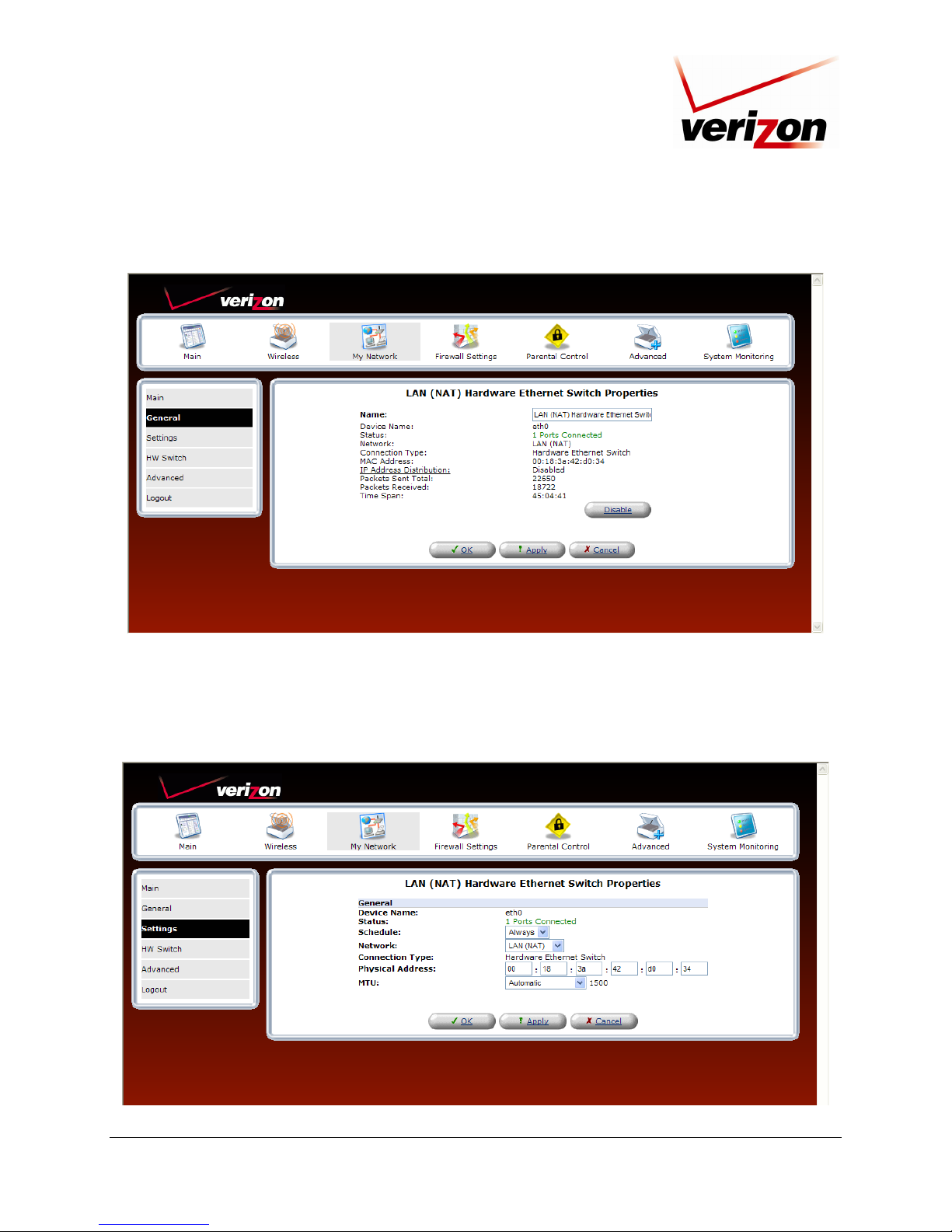
Verizon FiOS Router (Model 9100VM)
User Guide
If you clicked LAN (NAT) Hardware Ethernet Switch, the following screen will appear. If you change the
connection name, click Apply. Then, click OK to return to the Network Connections screen.
13.2.1.2 LAN (NAT) Hardware Ethernet Switch Properties—Settings
If you select Settings in the left submenu, the following screen will appear. Enter the desired properties for the
Ethernet switch, and then click Apply to save the settings.
030-300239 Rev. A 76 March 2008
Page 77

Verizon FiOS Router (Model 9100VM)
User Guide
13.2.1.3 LAN (NAT) Hardware Ethernet Switch Properties—HW Switch
If you select HW Switch in the left submenu. The following screen will appear. Enter the desired settings, and then
click Apply to save the settings.
13.2.1.4 LAN (NAT) Hardware Ethernet Switch Properties—Advanced
If you select Advanced in the left submenu, the following screen will appear. Click the New IP Address link to add
additional IP Address settings.
030-300239 Rev. A 77 March 2008
Page 78

Verizon FiOS Router (Model 9100VM)
User Guide
If you clicked New IP Address, the following screen will appear. Enter the IP Address and Subnet Mask, and then
click Apply to save the settings.
030-300239 Rev. A 78 March 2008
Page 79

Verizon FiOS Router (Model 9100VM)
User Guide
13.2.2 LAN (NAT) Wireless 802.11g Access Point
To view the LAN wireless properties, in the LAN (NAT) Bridge Properties screen, click LAN (NAT) Wireless
802.11g Access Point.
13.2.2.1 LAN (NAT) Wireless 802.11g Access Point Properties—General
If you click LAN (NAT) Wireless 802.11g Access Point and then click General in the left submenu, the following
screen will appear. If you change the LAN connection name in this screen, click Apply. Then, click OK to return to
the Network Connections screen.
030-300239 Rev. A 79 March 2008
Page 80

Verizon FiOS Router (Model 9100VM)
User Guide
13.2.2.2 LAN (NAT) Wireless 802.11g Access Point Properties—Settings
If you click Settings in the left submenu, the following screen will appear. If you change any settings in this screen,
click Apply.
13.2.2.3 LAN (NAT) Wireless 802.11g Access Point Properties—Wireless Status
If you click Wireless Status in the left submenu, the following screen will appear. After viewing this screen, click
Cancel to return to the preceding screen.
030-300239 Rev. A 80 March 2008
Page 81

Verizon FiOS Router (Model 9100VM)
User Guide
13.2.2.4 LAN (NAT) Wireless 802.11g Access Point Properties—Basic Security Settings
If you click Basic Security Settings in the left submenu, the following screen will appear. Please refer to section
12.2, “Basic Security Settings,” for details on this screen.
030-300239 Rev. A 81 March 2008
Page 82

Verizon FiOS Router (Model 9100VM)
User Guide
13.2.2.5 LAN (NAT) Wireless 802.11g Access Point Properties—Advanced Security Settings
If you click Advanced Security Settings in the left submenu, the following screen will appear. Please refer to
section 12.3, “Advanced Security Settings,” for details on this screen.
030-300239 Rev. A 82 March 2008
Page 83

Verizon FiOS Router (Model 9100VM)
User Guide
13.2.2.6 LAN (NAT) Wireless 802.11g Access Point Properties—Advanced
If you click Advanced in the left submenu, the following screen will appear. Click the New IP Address link to
configure additions IP address settings. Then click Apply to save the settings.
030-300239 Rev. A 83 March 2008
Page 84

Verizon FiOS Router (Model 9100VM)
User Guide
13.2.2.7 LAN (NAT) Bridge Properties—Settings
To configure the settings for the Router’s LAN (NAT) Bridge connections, in the Network Connections screen,
click the LAN (NAT) Bridge link. The following screen will appear. Enter the desired values, and then click Apply
to save the settings.
030-300239 Rev. A 84 March 2008
Page 85

Verizon FiOS Router (Model 9100VM)
User Guide
13.2.2.8 LAN (NAT) Bridge Properties—Routing
To configure the routing values for the Router’s LAN (NAT) Bridge connections, in the Network Connections
screen, click the LAN (NAT) Bridge link. Then, select Routing in the left submenu. The following screen will
appear. Select the desired setting from the Routing drop-down list.
If you selected Basic from the Routing drop-down list, the following screen will appear. The Router will use basic
routing operations for your LAN IP traffic. Click Apply to save the settings.
If you selected Advanced from the Routing drop-down list, the following screen will appear. Use this screen to
configure advanced routing instructions for IP traffic transmitted across your network. If you change any values in
this screen, click Apply to save the settings. To add a new Route, click the New Route link.
030-300239 Rev. A 85 March 2008
Page 86

Verizon FiOS Router (Model 9100VM)
User Guide
If you clicked New Route, the following screen will appear. Enter the appropriate values, and then click OK.
If you clicked OK in the preceding screen, the following screen will appear. This screen shows that a Route has
been added. Next, click Apply to save the settings.
030-300239 Rev. A 86 March 2008
Page 87

Verizon FiOS Router (Model 9100VM)
User Guide
13.2.2.9 LAN (NAT) Bridge Properties—Bridging
To configure the bridging values for the Router’s LAN (NAT) Bridge connections, in the Network Connections
screen, click the LAN (NAT) Bridge link. Then, select Bridging in the left submenu. The following screen will
appear. Enter the desired settings, and then click Apply to save the settings.
030-300239 Rev. A 87 March 2008
Page 88

Verizon FiOS Router (Model 9100VM)
User Guide
13.2.2.10 LAN (NAT) Bridge Properties – Advanced
To configure advanced settings for the Router’s LAN (NAT) Bridge connections, in the Network Connections
screen, click the LAN (NAT) Bridge link. Then, select Advanced in the left submenu. The following screen will
appear. To add a new IP Address, click the New IP Address link.
If you clicked New IP Addresses, the following screen will appear. Enter the desired values and click Apply.
030-300239 Rev. A 88 March 2008
Page 89

Verizon FiOS Router (Model 9100VM)
User Guide
13.2.3 WAN VDSL2 Properties
To view the WAN VDSL2 properties, in the following Network Connections screen, click the WAN VDSL2 link.
13.2.3.1 WAN VDSL2 Properties—General
Select General in the left submenu. The following screen will appear. This screen displays information about your
WAN VDSL2 connection. If you make changes to this screen, click Apply to save the settings.
030-300239 Rev. A 89 March 2008
Page 90

Verizon FiOS Router (Model 9100VM)
User Guide
13.2.3.2 WAN VDSL2 Properties—Settings
To configure the settings for your Router’s WAN VDSL2 connection, in the WAN VDSL2 Properties screen,
select Settings in the left submenu. The following screen will appear. Enter the appropriate values, and then click
Apply to save the settings.
030-300239 Rev. A 90 March 2008
Page 91

Verizon FiOS Router (Model 9100VM)
User Guide
13.2.3.3 WAN VDSL2 Properties—Routing
To configure the routing for your WAN VDSL2 connection, in the WAN VDSL2 Properties screen, select Routing
in the left submenu. Then, select the desired option from the Routing drop-down list, and then click Apply to save
the settings.
If you select Advanced from the Routing drop-down list, the following screen will appear. Enter the desired values,
and then click Apply to save the settings. To configure a new route, click the New Route link.
030-300239 Rev. A 91 March 2008
Page 92

Verizon FiOS Router (Model 9100VM)
User Guide
If you clicked New Route, the following screen will appear. Enter the appropriate values in the fields provided, and
then click OK to save the settings.
13.2.3.4 WAN VDSL2 Properties—QOS
To configure the QoS settings for your Router, in the WAN VDSL2 Properties screen, select QoS in the left
submenu. The following screen will appear. Enter the desired values, and then click Apply to save the settings.
030-300239 Rev. A 92 March 2008
Page 93

Verizon FiOS Router (Model 9100VM)
User Guide
13.2.3.5 WAN VDSL2 Properties—VDSL2
If you select VDSL2 in the left submenu of the WAN VDSL2 Properties screen, the following screen will appear.
View the transceiver information. To refresh this screen so that it displays the most current values, click Refresh.
13.2.3.6 WAN VDSL2 Properties—Advanced
To configure an additional IP address for your Router, in the WAN VDSL2 Properties screen, select Advanced in
the left submenu. The following screen will appear. Click the New IP Address link.
030-300239 Rev. A 93 March 2008
Page 94

Verizon FiOS Router (Model 9100VM)
User Guide
If you clicked New IP Address, the following screen will appear. Enter the desired values in the fields, and then
click Apply to save the settings.
030-300239 Rev. A 94 March 2008
Page 95

Verizon FiOS Router (Model 9100VM)
User Guide
13.2.4 WAN PPPoE Properties—Configuring WAN Ethernet
To configure the Router so that it connects to another DSL device via Ethernet, for example connecting to another
VDSL2 device that provides WAN access, you will need to change the WAN interface settings in your Router. To
do this, in the following Network Connections screen, click the WAN PPPoE link.
NOTE: When the Router is configured for this setting, the Router’s transceiver will be disabled. And the WAN
Ethernet port on the rear of the Router will be used to connect to another VDSL2 device.
13.2.4.1 WAN PPPoE Properties—General
If you clicked WAN PPPoE, the following screen will appear. Next, select Settings in the left submenu.
030-300239 Rev. A 95 March 2008
Page 96

Verizon FiOS Router (Model 9100VM)
User Guide
13.2.4.2 WAN PPPoE Properties—Settings
If you selected Settings in the left submenu, the following screen will appear. This screen allows you to select the
Router’s WAN Ethernet port on the rear of the Router for connection to another VDSL2 device, through which you
will connect to the Internet. Click the link labeled Underlying Connection.
If you clicked Underlying Connections, the following screen will appear. Select Ethernet from the WAN Interface
drop-down list.
IMPORTANT: When Ethernet is selected as the WAN interface port, the VDSL2 port on the rear of the Router
will not be used. (By factory default, the VDSL2 is the active WAN interface port.)
030-300239 Rev. A 96 March 2008
Page 97
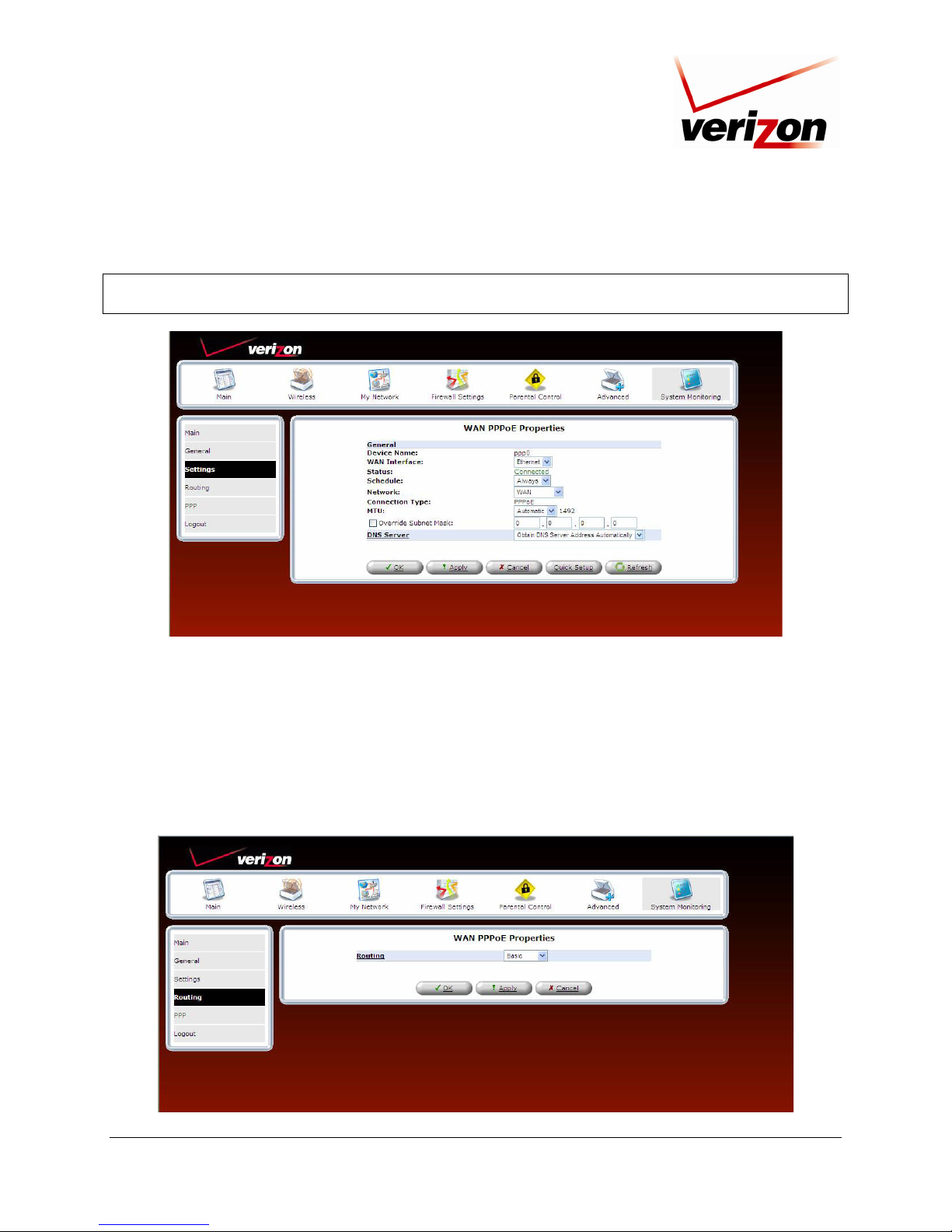
Verizon FiOS Router (Model 9100VM)
User Guide
If you selected Ethernet, the following screen will be displayed. Enter the appropriate values, and then click Apply
to save the settings.
NOTE: If you are using Ethernet as the WAN interface, be sure to install the Router according to the instructions
provided in section 6.4.3, “Connecting the Router via WAN Ethernet.”
13.2.4.3 WAN PPPoE Properties—Routing
To configure routing for the Router’s WAN VDSL2 connection, in the Network Connections screen, click the
WAN PPPoE link. Then, select Routing in the left submenu. The following screen will appear. Select the desired
setting from the Routing drop-down list. Click Apply to save the settings.
For example, if you selected Basic from the Routing drop-down list, the Router will use basic routing operations for
WAN IP traffic transmitted across your network. Click Apply to save the settings.
030-300239 Rev. A 97 March 2008
Page 98

Verizon FiOS Router (Model 9100VM)
User Guide
If you selected Advanced from the Routing drop-down list, the following screen will appear. This screen allows
you to configure advanced routing operations for WAN IP traffic transmitted across your network. If you change
any values in this screen, click Apply to save the settings. To add a new Route, click the New Route link.
If you clicked New Route, the following screen will appear. Enter the desired values, and then click OK.
030-300239 Rev. A 98 March 2008
Page 99

Verizon FiOS Router (Model 9100VM)
User Guide
If you clicked OK in the preceding screen, the following screen will appear. This screen shows that a Route has
been added to the Routing Table. Next, click Apply to save the settings.
13.2.4.4 WAN PPPoE Properties—PPP
To configure the PPP settings for the Router, in the Network Connections screen, click the WAN PPPoE link.
Then, select PPP in the left submenu. The following screen will appear. Enter the appropriate values in the fields,
and then click Apply to save the settings.
NOTE: The Login User name and Password are provided by Verizon.
030-300239 Rev. A 99 March 2008
Page 100

Verizon FiOS Router (Model 9100VM)
User Guide
13.2.5 LAN (NAT) Multimedia over COAX (MOCA)
To view the Router’s connection type for COAX (MOCA), in the Network Connections screen, click the LAN
(NAT) Multimedia over COAX (MOCA) link.
13.2.5.1 LAN (NAT) Multimedia over COAX (MOCA) Properties—General
Next, select General in the left submenu. The following screen will appear. If you change any values in this screen,
click Apply to save the settings.
030-300239 Rev. A 100 March 2008
 Loading...