

Page 1

Operations & Maintenance Manual
Page 2

0900‑5005 REV‑00
Page 3

Operations & Maintenance Manual
Effective: March 12, 2021
Caution: Federal (United States) law restricts this
system to sale by or on the order of a physician.
0900‑5005 REV‑00
Page 4

CONTACT INFORMATION
To obtain additional information regarding your BladderScan system,
contact Verathon CustomerCare or visit verathon.com/global‑support.
Verathon Inc.
20001 North Creek Parkway
Bothell, WA 98011 U.S.A.
Tel: +1 800 331 2313 (US and Canada only)
Tel: +1 425 867 1348
Fax: +1 425 883 2896
verathon.com
Verathon Medical (Europe) B.V.
Willem Fenengastraat 13
1096 BL Amsterdam
The Netherlands
Tel: +31 (0) 20 210 30 91
Fax: +31 (0) 20 210 30 92
Verathon Medical (Australia) Pty Limited
Unit 9, 39 Herbert Street
St Leonards NSW 2065
Australia
Within Australia: 1800 613 603 Tel / 1800 657 970 Fax
International: +61 2 9431 2000 Tel / +61 2 9475 1201 Fax
0123
Copyright © 2021 Verathon, Inc. All rights reserved.
BladderScan, the BladderScan symbol, BladderScan i10, BladderTraq, CaliScan, ImageSense, VMODE, Verathon, and the Verathon Torch
symbol are trademarks of Verathon Inc. All other brand and product names are trademarks or registered trademarks of their respective
owners.
Information in this manual may change at any time without notice. For the most up‑to‑date information, see the documentation
available at verathon.com/product‑documentation.
0900‑5005 REV‑00
Page 5

TABLE OF CONTENTS
IMPORTANT INFORMATION ................................................................................................................................1
OVERV IE W ........................................................................................................................................................ 1
Product Description ...................................................................................................................................... 1
Statement of Intended Use .......................................................................................................................... 1
Notice to All Users ........................................................................................................................................1
Essential Performance ..................................................................................................................................1
Environments of Intended Use ....................................................................................................................1
HIPAA Privacy ................................................................................................................................................2
SAFET Y INFORMATION ....................................................................................................................................2
Ultrasound Energy Safety ............................................................................................................................2
Contraindications ..........................................................................................................................................2
Warnings & Cautions ....................................................................................................................................2
INTRODUCTION ....................................................................................................................................................9
SYSTEM OVERVIEW .........................................................................................................................................9
Components & Accessories.........................................................................................................................10
SYSTEM FEATURES ......................................................................................................................................... 12
Console Features ......................................................................................................................................... 12
Probe Features ............................................................................................................................................ 14
Battery Features ..........................................................................................................................................15
SYS TEM ICON S ............................................................................................................................................... 15
Console Touchscreen Icons ......................................................................................................................... 15
Console Information Icons .........................................................................................................................18
Battery Indicator LED Colors ...................................................................................................................... 19
Console Battery Level Icons .......................................................................................................................20
Operations & Maintenance Manual: Table of Contents
i
0900‑5005 REV‑00
Page 6

SETTING UP ......................................................................................................................................................... 21
ASSEMBLING THE SYSTEM ............................................................................................................................21
Procedure 1. Perform the Initial Inspection .......................................................................................... 21
Procedure 2. Assemble the Workstation and Attach the System ........................................................ 22
Procedure 3. Insert a Battery .................................................................................................................23
Procedure 4. Charge the Battery ........................................................................................................... 25
Procedure 5. Install the Printer (Optional) ............................................................................................27
CONFIGURING SETT INGS ...............................................................................................................................28
Procedure 1. Configure General Settings .............................................................................................. 28
Procedure 2. Configure Administrative Settings ..................................................................................30
Procedure 3. Configure Exam Settings .................................................................................................. 32
Procedure 4. Configure Printed and PDF Report Settings ...................................................................33
Procedure 5. Customize Cost Savings Calculations ...............................................................................34
Procedure 6. Configure a PIN for Saved Exams .....................................................................................35
Procedure 7. Configure a PIN for System Settings ................................................................................36
USING THE SYSTEM ............................................................................................................................................ 37
MEASURING BLADDER VOLUME ..................................................................................................................37
Procedure 1. Prepare for the Exam........................................................................................................37
Procedure 2. Input Patient Information or Operator ID (Optional) ....................................................38
Procedure 3. Measure Bladder Volume .................................................................................................39
Procedure 4. Review Exam Results .........................................................................................................41
Procedure 5. Generate a Barcode containing an Exam Result .............................................................45
Procedure 6. Print, Save, or Exit an Active Exam ..................................................................................46
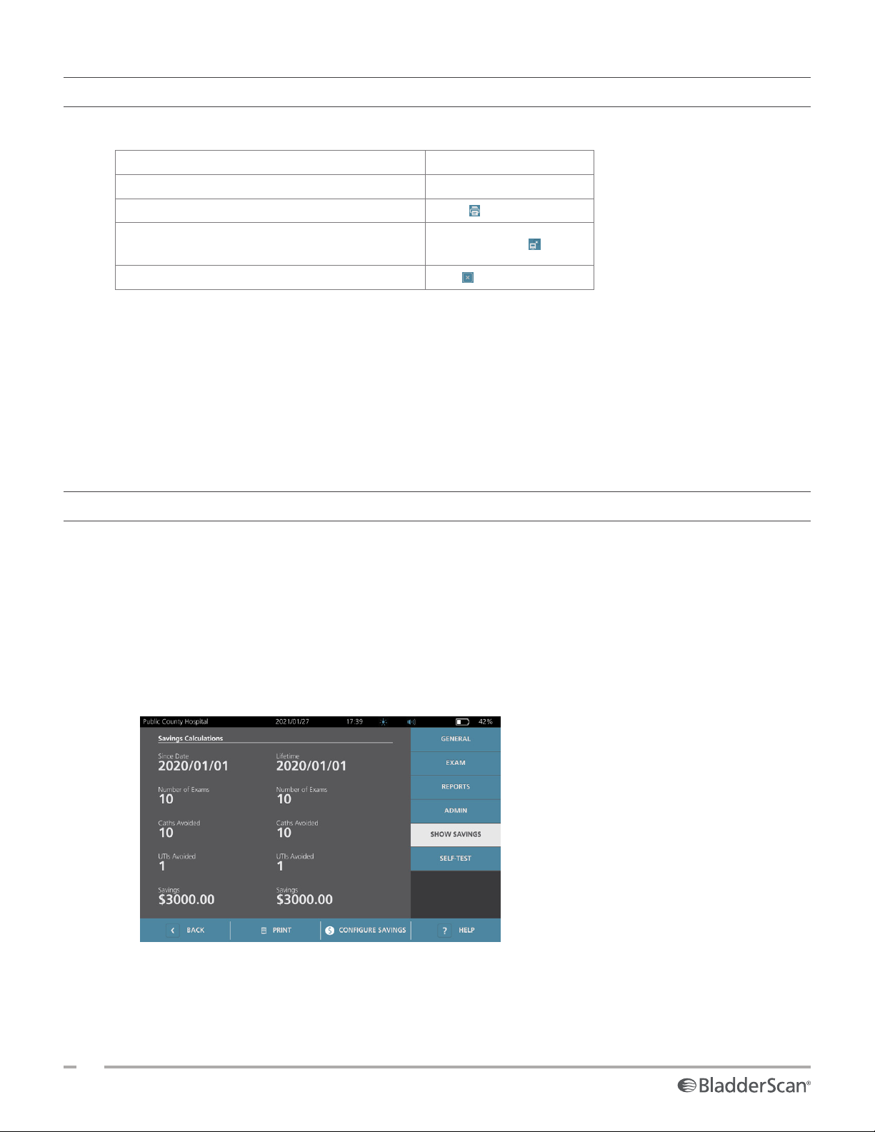
Procedure 7. View Cost Savings .............................................................................................................46
MANAGING SAVED EXAMS ..........................................................................................................................47
Procedure 1. Recall a Saved Exam ..........................................................................................................47
Procedure 2. Delete a Saved Exam ........................................................................................................48
Procedure 3. Export Saved Exams .......................................................................................................... 49
ii
0900‑5005 REV‑00
Page 7

REPROCESSING ...................................................................................................................................................50
CLEANERS & DISINFECTANTS ........................................................................................................................50
Disinfection Efficac y ...................................................................................................................................50
Compatibility ...............................................................................................................................................51
BEST PRACTICES & INSTRUCTIONS ...............................................................................................................52
Procedure 1. Clean & Disinfect the Console, Probe, & Cable ............................................................... 52
Procedure 2. Clean the Printer (Optional) .............................................................................................53
MAINTENANCE & SAFETY .................................................................................................................................54
REGULA R INS PEC T IO N S ................................................................................................................................. 54
CALIBRATION .................................................................................................................................................54
SYSTEM SOFT WARE ....................................................................................................................................... 55
DEVICE DISPOSAL ..........................................................................................................................................55
WARRANTY .................................................................................................................................................... 55
MAINTEN ANCE PROCEDURES ....................................................................................................................... 56
Procedure 1. Load Thermal Paper into the Printer (Optional) .............................................................56
Procedure 2. Run a Self‑Test ...................................................................................................................57
Procedure 3. Update the Software ........................................................................................................58
Procedure 4. Complete a CaliScan Test .................................................................................................. 59
Procedure 5. Turn the System Off ..........................................................................................................60
Procedure 6. Perform an Unconditional Shutdown ............................................................................. 61
Procedure 7. Copy the System’s Configuration to Other Systems .......................................................62
Procedure 8. Turn Off the USB Ports ..................................................................................................... 63
HELP & TROUBLESHOOTING ..............................................................................................................................64
HELP RESOURCES ...........................................................................................................................................64
Procedure 1. Watch the Onboard Tutorial ............................................................................................64
Operations & Maintenance Manual: Table of Contents
iii
0900‑5005 REV‑00
Page 8

DEVICE REPAIR ...............................................................................................................................................65
TROUBLESHOOT ING PROCEDURES ............................................................................................................... 65
Procedure 1. Troubleshoot Console Battery Issues ............................................................................... 65
Procedure 2. Troubleshoot Probe Connection Issues............................................................................66
Procedure 3. Troubleshoot Probe Aiming Issues ...................................................................................66
Procedure 4. Restore Factory Defaults .................................................................................................. 68
Procedure 5. Troubleshoot Irregular Printouts (Optional) ...................................................................69
Procedure 6. Clear a Paper Jam (Optional) ...........................................................................................71
Procedure 7. Replace the Printer Drive Roller (Optional) .....................................................................72
Procedure 8. Evaluate Console Error Messages .....................................................................................73
PRODUCT SPECIFICATIONS ................................................................................................................................ 74
SYSTEM SPECIFICATIONS ............................................................................................................................... 74
COMPONENT SPECIFICATIONS ...................................................................................................................... 77
ELECTROMAGNETIC COMPATIBILITY ...........................................................................................................81
ACCESSORY CONFORMANCE TO STANDARDS .............................................................................................84
GLOSSARY ...........................................................................................................................................................85
iv
0900‑5005 REV‑00
Page 9

IMPORTANT INFORMATION
OVERVIEW
PRODUCT DESCRIPTION
The BladderScan i10 system provides noninvasive measurement of urinary bladder volume. The system
calculates the bladder volume using ImageSense™, a proprietary Verathon artificial intelligence algorithm
that draws on real‑world data to create a consistent evaluation of the bladder’s location, size, and shape.
The primary components of the system are a console and a probe. The console’s touchscreen displays
critical information such as bladder volume, directional aiming with real‑time feedback, configuration and
administrative settings, and indicators for battery level and charging status. The touchscreen also provides
most of the system’s controls, both during exams and between them. A clinician with appropriate access
permission can use the touchscreen to retrieve stored exams at any time.
The console includes a bay for a rechargeable lithium‑ion battery. When the console is connected to external
power, it charges the battery.
STATEMENT OF INTENDED USE
The BladderScan i10 system is an ultrasound device intended to be used for measuring the urine volume in
the bladder noninvasively.
NOTICE TO ALL USERS
The BladderScan i10 system should be used only by individuals who have been trained and authorized
by a physician or the institution providing patient care. Users should read this entire manual before using
the system. Do not attempt to operate the system until you thoroughly understand all instructions and
procedures in this manual.
ESSENTIAL PERFORMANCE
Essential performance is the system performance necessary to avoid unacceptable risk. The essential
performance of the BladderScan i10 system is to produce ultrasonic output energy, display ultrasonic images,
and display numerical values for bladder volume. The system shall not produce unintended or excessive probe
surface temperature.
ENVIRONMENTS OF INTENDED USE
The BladderScan i10 system is intended to be used in professional healthcare environments such as hospitals,
clinics, and doctors’ offices.
Operations & Maintenance Manual: Important Information
1
0900‑5005 REV‑00
Page 10
HIPAA PRIVACY
The Health Insurance Portability and Accountability Act of 1996 (“HIPAA”) regulations require our customers
to monitor and limit the ways in which patients’ confidential information is accessed, used, stored,
transmitted, and disposed of. Our customers are ultimately responsible for ensuring all electronic health
information contained within the system is protected. In the course of providing services to customers,
Verathon will remove any electronic protected health information from the system, if such information is still
present.
SAFETY INFORMATION
ULTRASOUND ENERGY SAFETY
To date, exposure to pulsed diagnostic ultrasound has not been shown to produce adverse effects. However,
ultrasound should be used prudently, and total patient exposure should be kept as low as reasonably
achievable (ALARA). Following the ALARA principle, ultrasound should only be used by medical professionals
when clinically indicated, using the lowest possible exposure times necessary to obtain clinically useful
information. For more information on ALARA, refer to the American Institute of Ultrasound in Medicine
publication, Medical Ultrasound Safety.
The ultrasound output power of the BladderScan i10 system is not user adjustable and is limited to the
minimum level necessary for effective performance. For more information about acoustic output levels, see
the chapter “Product Specifications” on page74.
CONTRAINDICATIONS
The BladderScan i10 system is not intended for fetal use or for use on fetal patients, pregnant patients,
patients with open skin or wounds in the suprapubic region, or patients with ascites.
WARNINGS & CAUTIONS
Warnings indicate that injury, death, or other serious adverse reactions may result from use or misuse of the
system. Cautions indicate that use or misuse of the system may cause a problem, such as a malfunction,
failure, or damage to the product. Throughout the manual, pay attention to sections labeled Important, as
these contain reminders or summaries of the following cautions as they apply to a specific component or
usesituation. When using the system, heed the following warnings and cautions.
WARNINGS
WARNING
Do not use the system on:
•Fetal patients.
•Pregnant patients.
•Patients with open skin or wounds in the suprapubic region.
•Patients with ascites.
2
0900‑5005 REV‑00
Page 11
WARNING
Be aware of the following conditions that can affect ultrasound transmission:
•Catheterization—A catheter in the patient’s bladder may affect the accuracy of the bladder
volume measurement in two ways: 1) by introducing air into the bladder that may block the
ultrasound signal, and 2) by having the catheter‑retaining balloon interfere with the volume
measurement. However, the volume measurement may still be clinically useful if it is large
(detecting a blocked catheter, for example).
•Abdominal Surgery—Scar tissue, surgical incisions, sutures, and staples can affect ultrasound
transmission. Use care when scanning patients who have had abdominal surgery.
WARNING
Accuracy is compromised if you do not obtain an optimal, repeatable image.
WARNING
Anatomical features surrounding the bladder can interfere with accurate scanning. When aiming
the probe, ensure that the entire bladder is in view and centered.
WARNING
Do not use water or surgical lubricants as a substitute for ultrasound gel. Substituting these or
other materials can cause incorrect scan results.
WARNING
This product may only be cleaned and disinfected by using the approved processes provided in
this manual. Cleaning and disinfection methods listed are recommended by Verathon based on
compatibility with component materials.
WARNING
Cleaning is critical to ensuring the component is ready for disinfection. Failure to properly clean
the device could cause contamination to remain after the disinfection procedure is complete.
WARNING
Ensure that you follow the manufacturer’s instructions for handling and disposing of the
cleaning and disinfection solutions provided in this manual.
Operations & Maintenance Manual: Important Information
3
0900‑5005 REV‑00
Page 12
WARNING
To reduce the risk of explosion, do not use the system in the presence of anesthetic substances
that can catch fire if exposed to an existing fire or an electrical spark.
WARNING
To reduce the risk of electric shock or burns, do not use the system in conjunction with
high‑frequency surgical equipment.
WARNING
Do not use accessories, transducers, or cables other than those specified or provided by
Verathon. Use of other such devices may cause this system to emit excessive electromagnetic
energy or to pick up unwanted electromagnetic signals or noise from its surroundings. These
malfunctions may cause improper operation, procedure delays, or both.
WARNING
Portable radio frequency communications equipment (including peripherals such as antenna
cables and external antennas) may not be used within 30 cm (12 inches) of any part of the
BladderScan system, including cables that Verathon specifies or provides for use with the
system. If this distance is not maintained, performance of the system may be degraded and
image display may be compromised.
WARNING
Use of this equipment adjacent to or stacked with other equipment should be avoided because
it could result in improper operation. If such use is necessary, this equipment and the other
equipment should be observed to verify that they are operating normally.
4
0900‑5005 REV‑00
Page 13
WARNING
To reduce the risk of leakage, explosion, fire, or serious injury, note the following when handling
the lithium‑ion battery included in the system:
•Remove the battery from the console if it is out of use for an extended period of time.
•Do not use the optional battery charger to charge the battery within 1.83 m (6 ft) of any
patient, including the furniture containing the patient (such as a bed or exam table).
•Do not charge the battery in any area where oxygen is administered.
•Never short‑circuit the battery by bringing the battery terminals into contact with any other
conductive object.
•Never expose the battery to abnormal shock, vibration, or pressure.
•Use a general‑purpose cleaner, such as an all‑purpose spray cleaner or a cloth moistened
with soap and water, to clean the battery. Do not clean or disinfect the battery using any of the
cleaning or disinfection materials described in the Reprocessing chapter of this manual.
•Do not disassemble the battery, heat it above 60°C (140°F), or incinerate it.
•Keep the battery out of reach of children and in its original package until you are ready to
use it.
•Dispose of used batteries promptly according to local recycling or waste regulations.
•If the battery is leaking or its case is cracked, put on protective gloves to handle it, and
discard it immediately.
•Put insulating tape, such as cellophane tape, on the electrodes during transportation.
WARNING
To maintain electrical safety, use only the battery, power adapter, and power cord supplied
with the system. Use only Verathon‑recommended accessories and peripherals, including the
accessory battery charger.
WARNING
To reduce the risk of electrical shock, do not attempt to open the system components. This
may cause serious injury to the operator or damage to the system and will void the warranty.
Contact Verathon CustomerCare or your local representative for all servicing needs.
WARNING
To maintain electrical safety, inspect the power adapter for damage before each use. Do not use
a power adapter with cracks, broken wiring insulation, or other damage. If the power adapter is
damaged, contact Verathon CustomerCare or your local representative.
Operations & Maintenance Manual: Important Information
5
0900‑5005 REV‑00
Page 14
WARNING
To maintain electrical safety, if you are using the accessory battery charger, inspect the charger
for damage before each use. Do not use a battery charger with cracks or other damage. If the
battery charger is damaged, contact Verathon CustomerCare or your local representative.
WARNING
If the battery is overheating or drawing excessive current, turn the system off and disconnect
external power immediately. Allowing overheating or excess current draw to continue can
start a fire or cause an electrical injury. For help with battery malfunctions, contact Verathon
Customer Care.
WARNING
No modification of this equipment is allowed.
WARNING
To avoid the risk of injury, when the printer door is open:
•Do not touch the printer mechanism or print head, which may be hot from recent printing.
•Do not touch the edge of the paper cutter.
WARNING
Never use the BladderScan i10 system to display the image of anatomical features other than the
bladder.
WARNING
This system is intended as a measuring tool only. It is not a diagnostic device.
WARNING
Use only a passive‑type USB flash drive. Do not use USB drives powered by another external
source.
6
0900‑5005 REV‑00
Page 15
CAUTIONS
CAUTION
Statement of Prescription: Federal (United States) law restricts this device to sale by or on the
order of a physician.
CAUTION
Before scanning a patient, make sure that a battery is installed and properly charged. The
system cannot scan while connected to external power.
CAUTION
To avoid damage to cables and accessories, do not excessively twist or bend cables associated
with the system.
CAUTION
To dispose of the system or accessories at the end of their useful service life, see the section
“Device Disposal”. The system and related devices may contain mineral oils, batteries, and other
environmentally hazardous materials.
CAUTION
Before you perform any system upgrade, self‑test, or maintenance procedure, make sure that
a battery is installed and charged to a level of at least 20%. Disconnect external power before
performing a system upgrade.
Operations & Maintenance Manual: Important Information
7
0900‑5005 REV‑00
Page 16

CAUTION
Medical electrical equipment requires special precautions regarding electromagnetic
compatibility (EMC) and must be installed and operated according to the instructions in this
manual. For more information, see the “Electromagnetic Compatibility” section.
This device can radiate radio frequency energy and is very unlikely to cause harmful interference
with other devices in the vicinity. There is no guarantee that interference will not occur in a
particular installation. Evidence of interference may include degradation of performance in this
device or other devices when operated simultaneously. To correct interference, use the following
measures:
•Turn devices on and off in the vicinity to determine the source of interference.
•Reorient or relocate this device or other devices.
•Increase the separation between devices.
•Connect the device to an outlet on a circuit different than the other device(s).
•Eliminate or reduce EMI with technical solutions (such as shielding).
•Purchase medical devices that comply with the IEC60601‑1‑2standard.
•Be aware that portable and mobile radio frequency communications equipment (cellular
phones, etc.) may affect medical electrical equipment; take appropriate precautions during
operation.
CAUTION
Failure to follow these instructions may cause device damage not covered by the warranty:
•Do not immerse any system component in cleaning or disinfectant solution or other liquids.
•Do not subject any system component to steam, ethylene oxide, radiation, or similar methods
of sterilization or autoclaving.
•Do not use metal or abrasive brushes. These may scratch a component of the system, causing
permanent damage.
8
0900‑5005 REV‑00
Page 17
INTRODUCTION
SYSTEM OVERVIEW
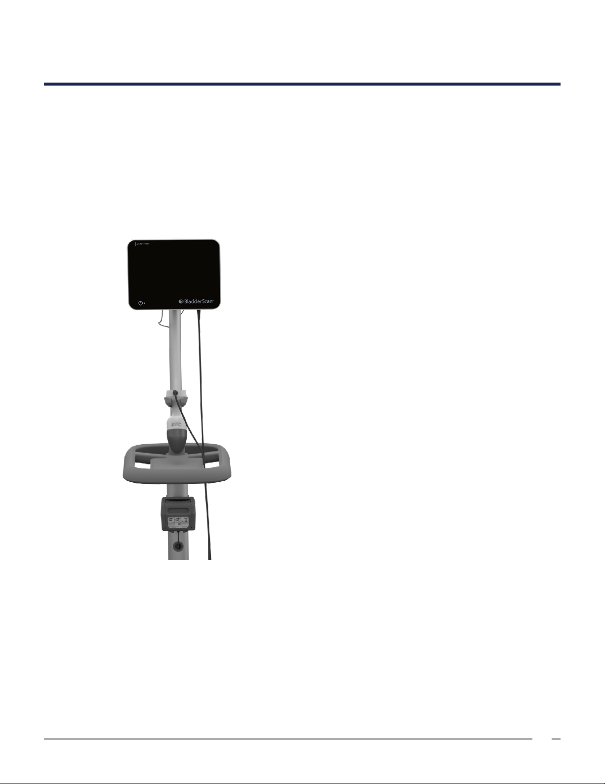
BladderScan i10 is a 3D ultrasound system that measures bladder volume noninvasively. The core components
of the system are a console with a touchscreen display and a probe containing the ultrasound transducer. The
system also includes a rechargeable battery. Available accessories and configuration options for the system
include a mobile workstation, a printer, an external battery charger, and extra rechargeable batteries. For
more information, see “Components & Accessories” on page10.
Figure 1. BladderScan i10 System (Showing Accessory Printer and Workstation)
The system includes an onboard tutorial as well as integrated help screens. The console features a variety of
customizable settings and a Saved Exams function that allows you to recall, print, or transfer saved exams.
The console also features an optional live imaging pre‑scan mode that enables you to locate the bladder by
displaying a B‑mode view of the abdomen in real time, before completing the volume measurement scan.
Operations & Maintenance Manual: Introduction
9
0900‑5005 REV‑00
Page 18
COMPONENTS & ACCESSORIES
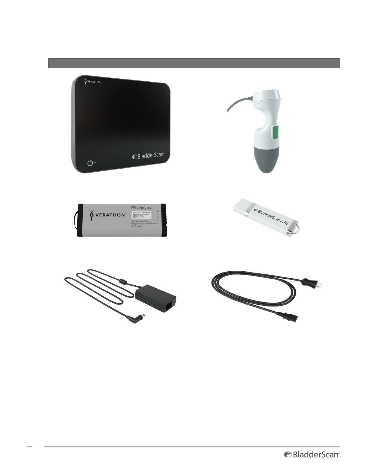
Table 1. Included System Components & Accessories
INCLUDED SYSTEM COMPONENTS & ACCESSORIES
Console Probe
Battery
Power adapter Power cord
In‑service USB flashdrive
Note: Plug may vary by region
10
0900‑5005 REV‑00
Page 19
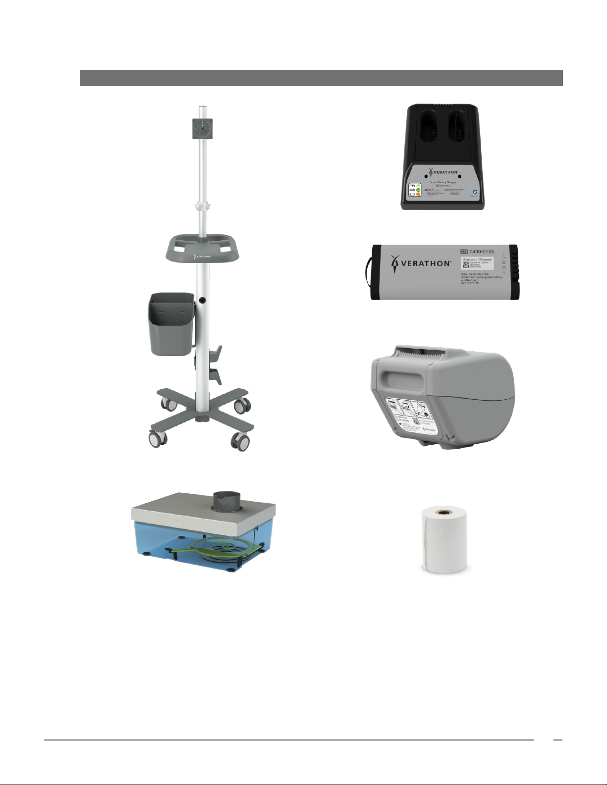
Table 2. Optional System Components & Accessories
OPTIONAL SYSTEM COMPONENTS & ACCESSORIES
Battery Charger
Extra Battery
Mobile Workstation Printer
Calibration Kit Thermal Paper
Additionally, quick reference materials and ultrasound gel may be available for order in your
region. For more information, contact Verathon CustomerCare or your local representative or visit
verathon.com/global‑support.
Operations & Maintenance Manual: Introduction
11
0900‑5005 REV‑00
Page 20
SYSTEM FEATURES
CONSOLE FEATURES
Read the “Warnings & Cautions” section before using the system.
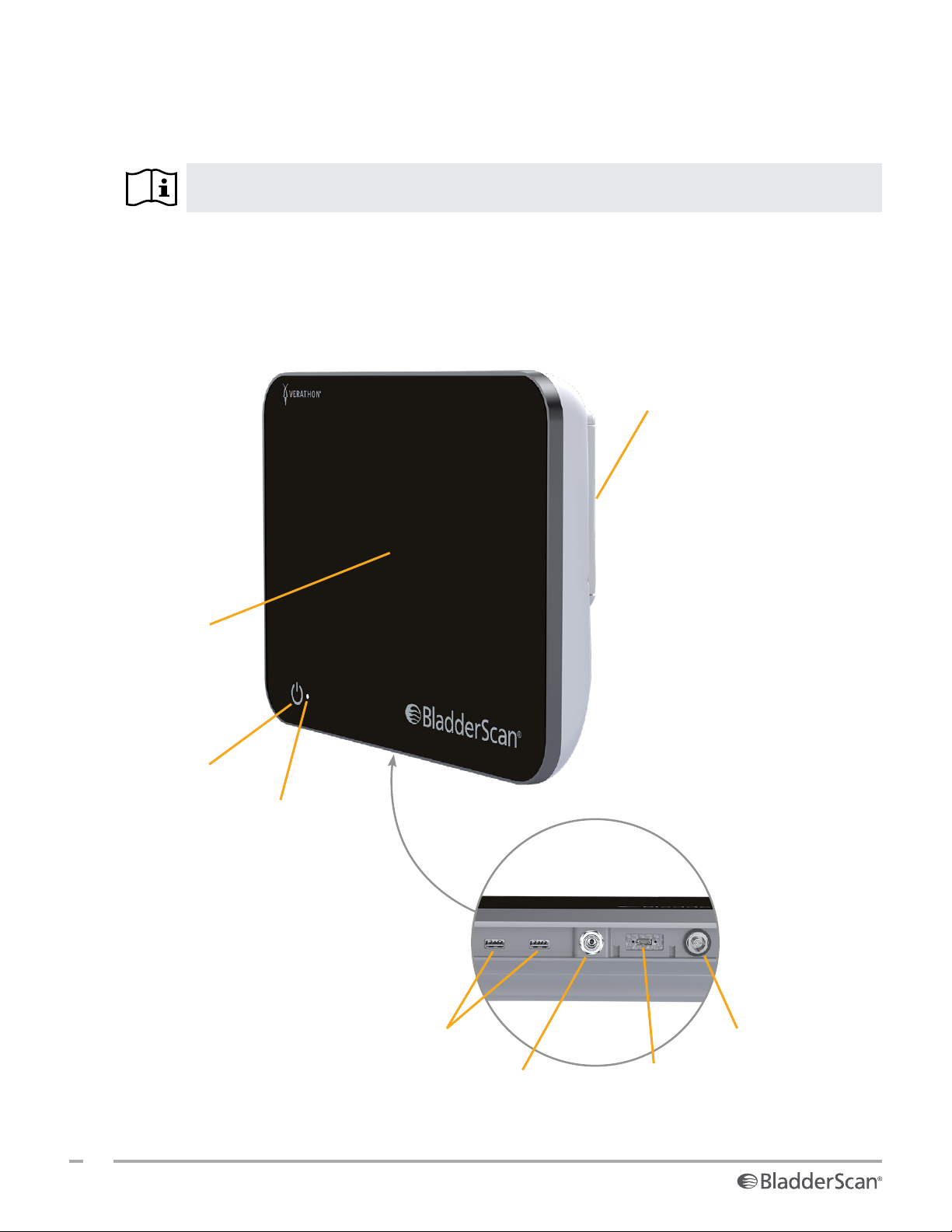
The console’s primary feature is a touchscreen display that allows you to perform scans, manage scan results,
and customize settings. A rechargeable battery is inserted into one side of the console, and the bottom surface
includes a selection of ports for connecting system components and accessories such as external, removable
media storage devices. You may also customize your console by adding an optional printer.
Figure 2. Console Features
Battery door
Main display
On/Off button
Battery indicator LED
Probe cable portUSB ports
USB‑C portPower port
12
0900‑5005 REV‑00
Page 21
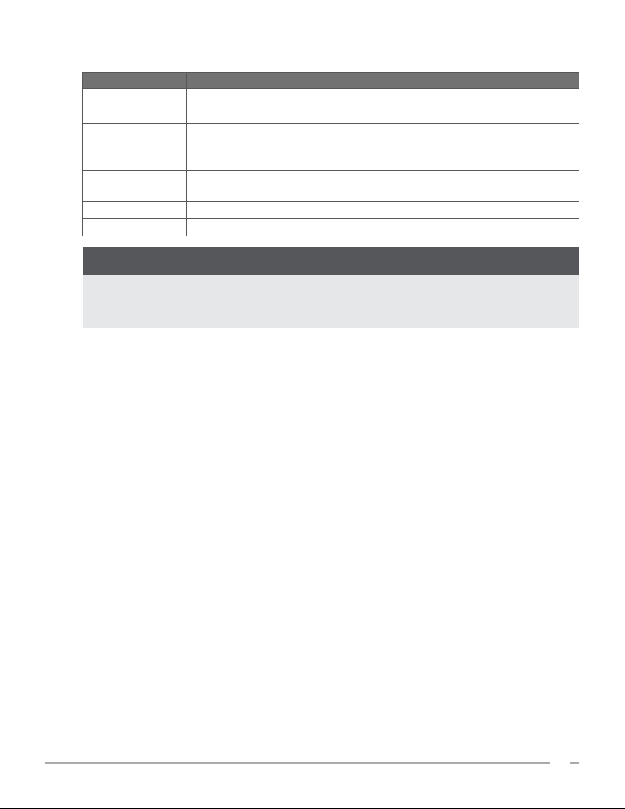
Table 3. Console Feature Descriptions
PART NAME PURPOSE
Main display Features touchscreen controls of the system user interface.
Battery door Opens to access and replace the rechargeable battery.
On/Off button
Turns the system on or off. When the system is turned on or charging a battery, an
LED next to the On/Off button is illuminated.
Probe cable port Connects the probe to the console.
USB ports
Provides a connection for the optional printer and for external, removable storage
media.
USB‑C port Provides a connection for external, removable storage media.
Power port Connects the power adapter to the console.
IMPORTANT
If you press the On/Off button and hold it for more than two seconds, the console starts an
unconditional shutdown process. Under some circumstances, this process can result in the loss of
unsaved information.
Operations & Maintenance Manual: Introduction
13
0900‑5005 REV‑00
Page 22
PROBE FEATURES
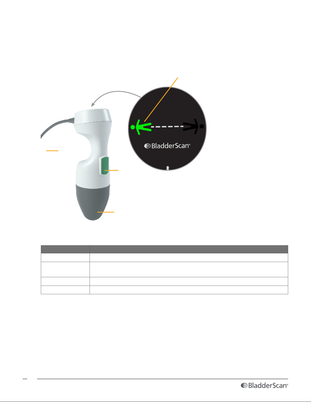
The probe contacts the patient and transmits and receives ultrasound waves, automatically moving its
internal transducer to scan twelve planes to produce a three‑dimensional image of the bladder. The probe is
attached to the console by a cable.
Figure 3. Probe Features
Probe cable
Direction indicator
Probe button
Probe dome
Table 4. Probe Features
PART NAME PURPOSE
Probe button Starts aiming or scanning when pressed.
Direction indicator
Displays the probe orientation selected for the current scan. The lighted human figure
indicator should be oriented in the same direction as the patient.
Probe cable Connects the probe to the console.
Probe dome Contacts the patient’s abdomen and transmits ultrasound.
14
0900‑5005 REV‑00
Page 23
BATTERY FEATURES
The system is powered by a lithium‑ion battery. Additional or replacement batteries can be ordered if
needed.
The BladderScan i10 console serves as the main battery charger. To charge a battery, the console must
be connected to a wall outlet using the power adapter and power cord provided. Use only the console or
the optional Verathon battery charger to charge the battery; any other battery charger may damage it. To
prevent incorrect connections, the battery is shaped so that it can be inserted into the console in only the
correct orientation.
The console automatically detects whether or not it is connected to external power. While the console is
connected, it deactivates the probe’s scanning functions.
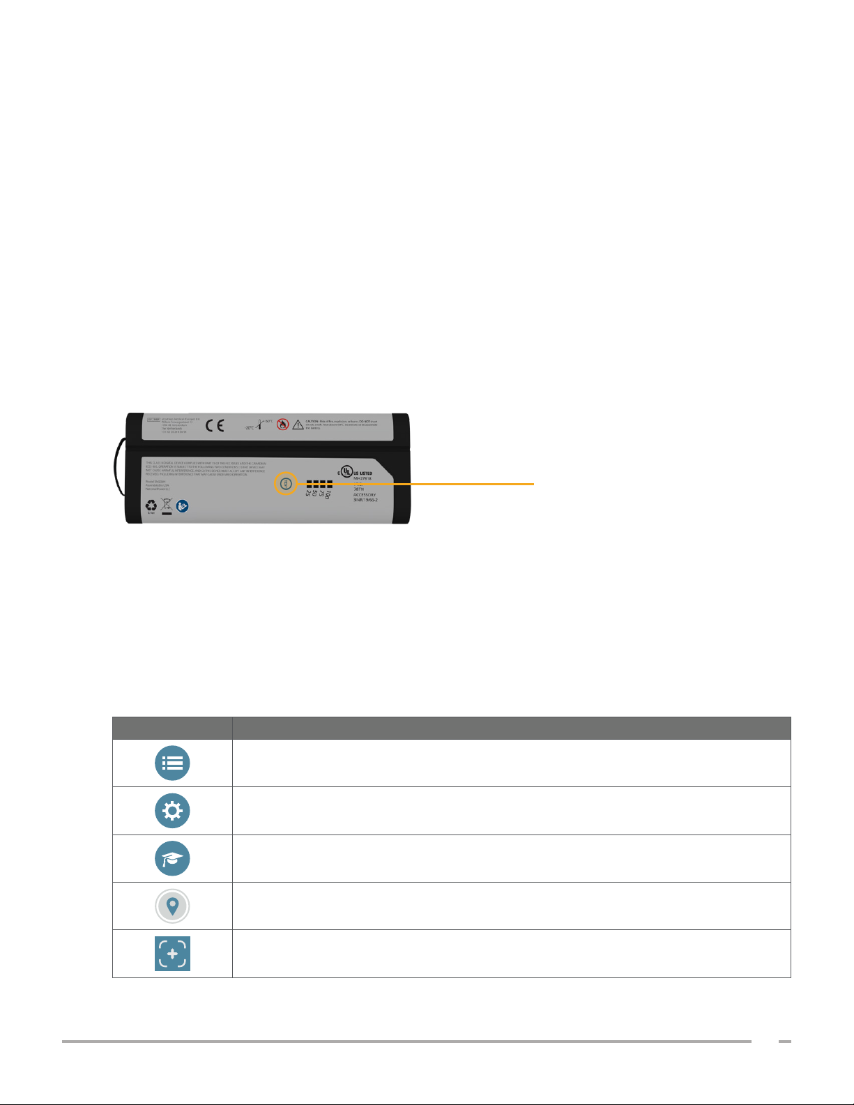
Each battery features a test button that allows you to check the charge level of the battery without inserting
it into the console. If you press the Tes t button on the back of the battery, the display next to the test button
illuminates to display the approximate charge level: 25%, 50%, 75%, or 100%.
Figure 4. BladderScan i10 Lithium‑Ion Battery
Test button
SYSTEM ICONS
CONSOLE TOUCHSCREEN ICONS
The console touchscreen displays the interface that controls the system. The icons in Table 5 may appear on
the screen, and you may tap them to complete the function associated with theicon.
Table 5. Touchscreen Icons
ICON FUNCTION
Saved Exams—On the Home screen, view all exams that are saved to the console.
Settings—On the Home screen, open the Settings screen.
Tutorial—On the Home screen, view the onboard tutorial.
Position—On the Home screen, select which side of the patient you are located on
during the exam.
Scan—Start scanning the patient.
Operations & Maintenance Manual: Introduction
15
0900‑5005 REV‑00
Page 24
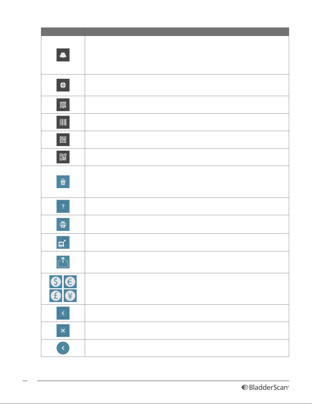
ICON FUNCTION
B‑Mode—View the ultrasound image as pairs of two‑dimensional, orthogonal planes
from the three‑dimensional scan. The contours of detected features are overlaid on the
image.
Note: You may disable the display of the detected contours. For more information, see
“Configure Exam Settings” on page32.
C‑Mode—View the ultrasound image as a cross‑section view of the three‑dimensional
scan. The C‑Mode image consists of a circular region with a crosshair overlay. This
image displays the bladder shape and, if detected, the shadow of the pubic bone.
Aztec Code—Display a summary of the scan results as an Aztec code (with the
positioning square in the center).
Code 128—Display a summary of the scan results as a barcode in Code 128 format.
Data Matrix—Display a summary of the scan results as a Data Matrix.
QR Code—Display a summary of the scan results as a QR code (with positioning
squares at the corners).
Delete—On the Results screen, delete the displayed scan and its volume. (The system
retains all other scans and all patient information.)
On the Saved Exams screens, delete a saved exam (either the currently displayed exam
or an exam selected in a list).
Help—Start the onboard tutorial or display screen‑sensitive help text.
Print—Print the scan, self‑test, or savings calculation results.
Note: This function is only available if you have attached the optional printer.
Save and Exit—On the Results screen, save the scan result with the largest volume and
return to the Home screen.
Export Exams—On the Saved Exams screen, move exams from the system’s internal
memory to an external USB drive. This option is only available if an external drive is
connected.
Configure Savings—Customize the values for calculating the cost savings that result
from scanning rather than catheterizing patients.
Back—Return to the previous screen or the Home screen.
Exit—On the Results screen, exit the exam without saving and return to the Home
screen.
16
0900‑5005 REV‑00
Previous—While viewing B‑mode images on the Results screen, return to the previous
scan plane or angle.
Page 25
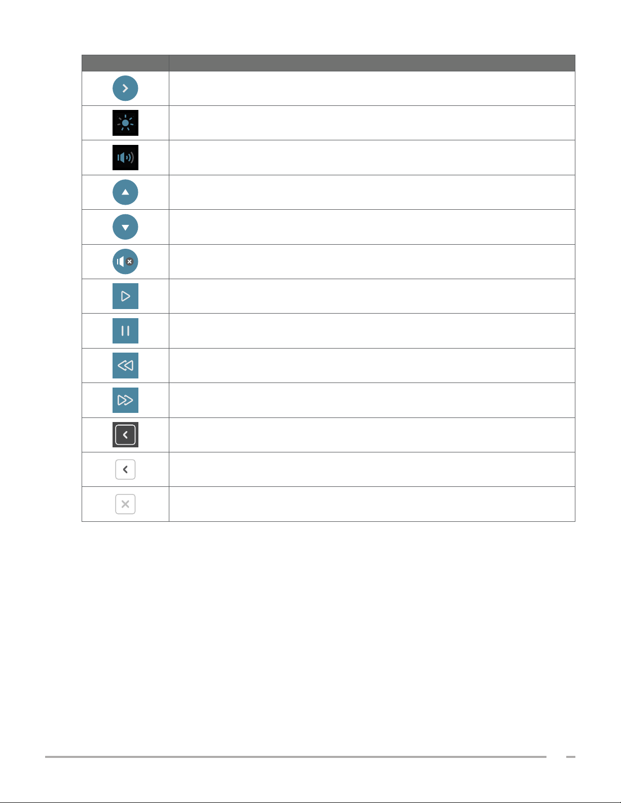
ICON FUNCTION
Next—While viewing B‑mode images on the Results screen, advance to the next scan
plane or angle.
Brightness—Adjust the brightness of the touchscreen. The icon shows the current
setting.
Volume—Adjust the volume of sounds played through the console’s speaker. The icon
shows the current setting.
Increase—Turn up the brightness or volume.
Decrease—Turn down the brightness or volume.
Mute—Turn the speaker on or off.
Play—While viewing the onboard tutorial, start or resume playback.
Pause—While viewing the onboard tutorial, pause playback.
Previous—While viewing the onboard tutorial, return to the previous frame.
Next—While viewing the onboard tutorial, advance to the next frame.
On the Results screen, expand the history list of scans taken during the current exam.
On the Results screen, close the history list of scans taken during the current exam.
Close the Barcode window or a warning dialog box.
Operations & Maintenance Manual: Introduction
17
0900‑5005 REV‑00
Page 26
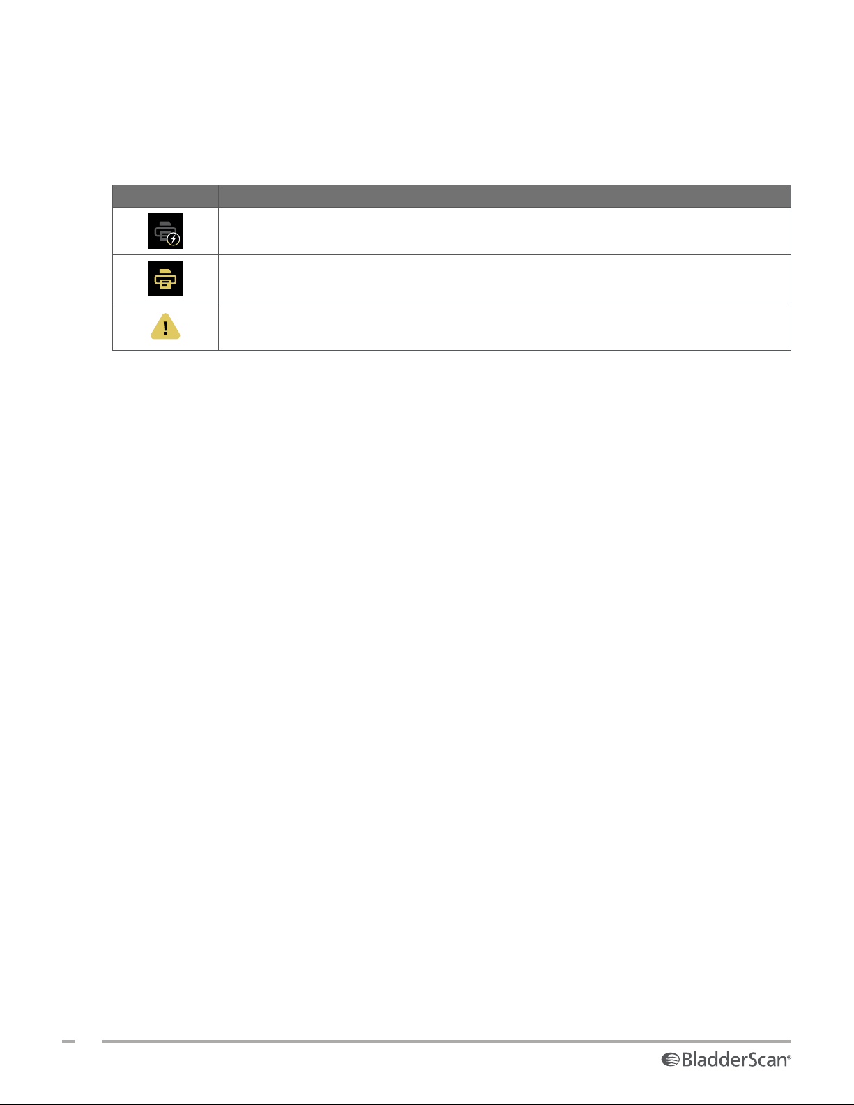
CONSOLE INFORMATION ICONS
The icons in Table 6 provide information about the status of the system, but tapping them does not affect
the system.
Table 6. Information Icons
ICON FUNCTION
The printer is charging, but it does not have enough charge left in its built‑in internal
battery to operate correctly.
The printer cannot operate because of a problem with its built‑in internal battery.
Note the accompanying alert.
18
0900‑5005 REV‑00
Page 27
BATTERY INDICATOR LED COLORS
WARNING
If the battery is overheating or drawing excessive current, turn the system off and disconnect
external power immediately. Allowing overheating or excess current draw to continue can
start a fire or cause an electrical injury. For help with battery malfunctions, contact Verathon
Customer Care.
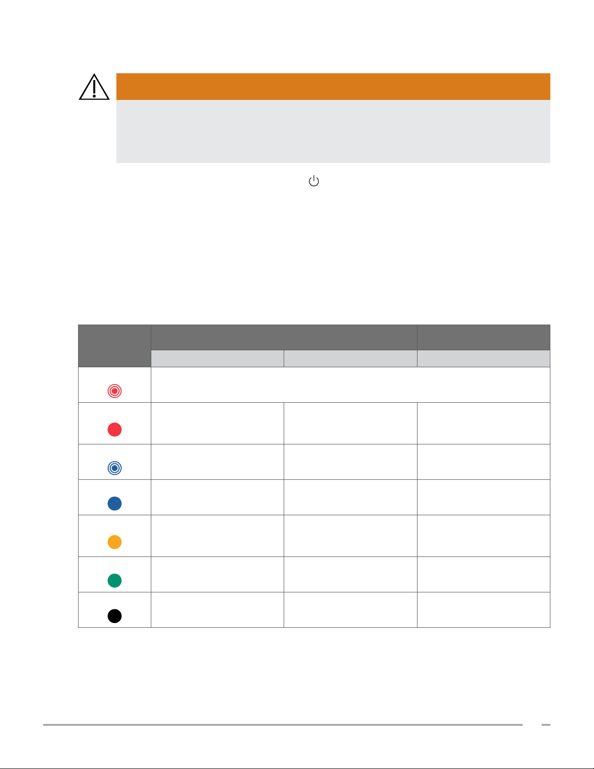
The battery indicator LED next to the On/Off button shows the current condition of the console’s battery.
Except in cases where the battery is overheating or drawing excessive current (shown when the LED flashes
red), the LED displays the battery’s current charge level.
The system charges the battery whenever it is connected to external power. If the system is on at the same
time, the battery cannot quite reach full charge, so the system charges it continuously. If the system is
connected to external power but is turned off, it stops charging once the battery is fully charged.
Table 7 shows how the battery indicator LED reports the condition of the battery based on whether the
system is connected to external power and whether it is turned on or off.
Table 7. Battery Indicator LED Colors
COLOR
Flashing red
Steady red
Flashing blue
Steady blue
Steady yellow
Steady green
Unlit
CONNECTED TO EXTERNAL POWER
NOT CONNECTED TO
EXTERNAL POWER
System On System Off System On
Overheating or drawing excessive current
Greater than or equal to
Less than 2% —
5%, less than or equal to
10 %*
— Less than 2% —
— Greater than or equal to 2% —
Greater than or equal to
2%, less than or equal to
20%
—
Greater than 10%, less than
or equal to 20%
Greater than 20% — Greater than 20%
— Fully charged
†
—
* Note: If the system is on but not connected to external power, and the battery level is less than 5%, the system attempts to shut itself
down automatically. During the automatic shutdown, the battery indicator LED remains red.
† Note: If you insert a battery that is completely depleted and then connect external power to the console, the battery indicator LED
remains unlit. In such cases, the battery is not charged enough for the console to detect it. Press the On/Off button to begin charging
the battery.
Operations & Maintenance Manual: Introduction
19
0900‑5005 REV‑00
Page 28
CONSOLE BATTERY LEVEL ICONS
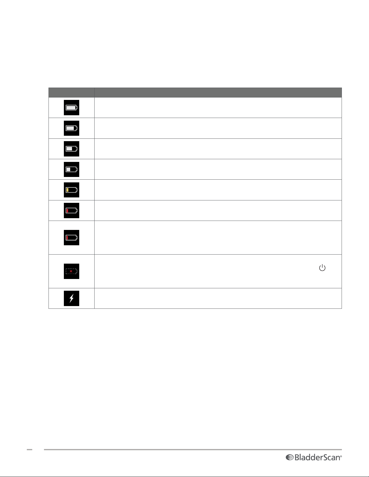
The battery level icon is displayed in the status bar at the top of the touchscreen. The icon and the
percentage value next to it indicate the remaining battery power. For information about charging the battery,
see the procedure “Charge the Battery” on page25.
Table 8. Battery Level Icon
ICON FUNCTION
The battery is fully or almost fully charged.
The battery is approximately 80% charged.
The battery is approximately 60% charged.
The battery is approximately 40% charged.
The battery is approximately 20% charged. Replace with a fresh battery or connect
external power.
The battery is approximately 10% charged. Replace with a fresh battery or connect
external power.
The battery is less than 5% charged. Replace the battery or connect external power
immediately. At this point, the system turns itself off if external power is not connected.
If external power is connected, the system software may be temporarily unable to detect
the battery while charging begins.
The battery is not present, or it cannot be detected because its charge level is too low
(less than 2%). If external power is connected, the LED next to the On/Off button is
red instead of yellow or green. If you turn the system off under these conditions, the LED
flashes blue and the system continues to charge the battery.
The battery is charging.
20
0900‑5005 REV‑00
Page 29

SETTING UP
To help you get started, these topics explain how to assemble the system:
1. Perform the Initial Inspection
2. Assemble the Workstation and Attach the System
3. Insert a Battery
4. Charge the Battery
5. Install the Printer (Optional)
Once the system is assembled, you can configure user settings and add custom information:
6. Configure General Settings
7. Configure Administrative Settings
8. Configure Exam Settings
9. Configure Printed and PDF Report Settings
10. Customize Cost Savings Calculations
11. Configure a PIN for Saved Exams
12. Configure a PIN for System Settings
ASSEMBLING THE SYSTEM
PROCEDURE 1. PERFORM THE INITIAL INSPECTION
When you receive the system, Verathon recommends that an operator familiar with the system perform a full
visual inspection for any physical damage that may have occurred during shipment.
1. Carefully open the top of the shipping box. Do not insert anything sharp through the box.
2. Remove the contents and verify that you have received the appropriate components for your system.
3. Inspect the components for damage.
4. If any of the components are missing or damaged, notify the carrier and Verathon CustomerCare or your
local representative.
Operations & Maintenance Manual: Setting Up
21
0900‑5005 REV‑00
Page 30
PROCEDURE 2. ASSEMBLE THE WORKSTATION AND ATTACH THE SYSTEM
Refer to the BladderScan i10 Workstation Assembly Quick Start Sheet (part number 0900‑5007) for
instructions on how to perform these tasks:
• Assemble the workstation
• Install the power adapter in the workstation
• Install the printer (if you have purchased the printer along with the system)
This procedure describes how to mount the console on an assembled workstation.
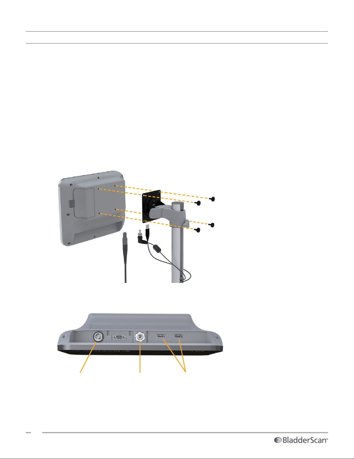
1. Position the console in front of the console mount on the workstation.
2. Insert four console mounting screws (part F in the hardware kit shipped with the workstation) through
the holes at the corners of the console mount and into the corresponding holes on the workstation.
Finger‑tighten all four screws securely.
Note: The console mount on the workstation uses a combination of spring tension and friction to
maintain the position of the console. It can be adjusted without tools at any time.
3. Connect the probe cable, the power cable, and the USB printer cable to the monitor as shown in the
following figure.
Probe Power Printer
Tip: You can connect the printer to either of the USB ports indicated in the figure. However, connecting
it to the USB port closest to the power port makes it easier to connect USB drives later. Do not attempt
to connect the printer to the USB‑C port between the probe port and the power port.
22
0900‑5005 REV‑00
Page 31
PROCEDURE 3. INSERT A BATTERY
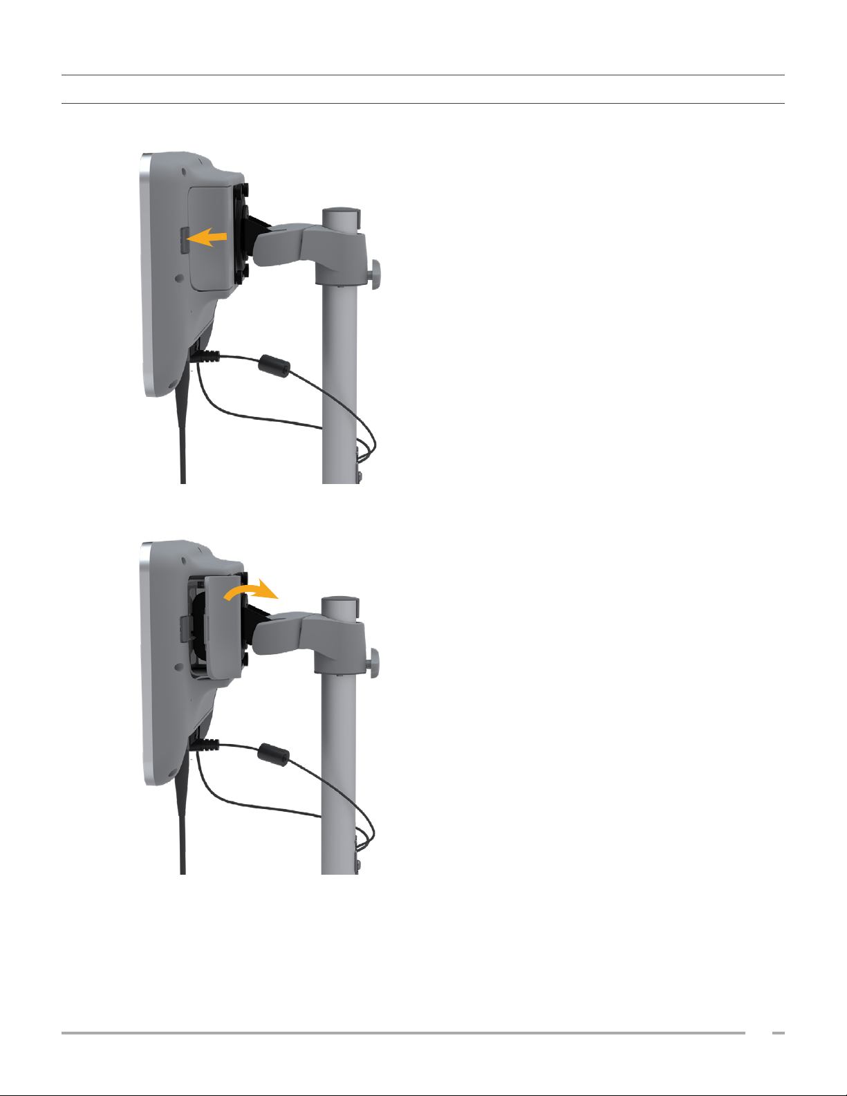
1. Slide the latch away from the battery well door on the console, and then open the door.
2. Move the door away from the battery well.
Operations & Maintenance Manual: Setting Up
23
0900‑5005 REV‑00
Page 32
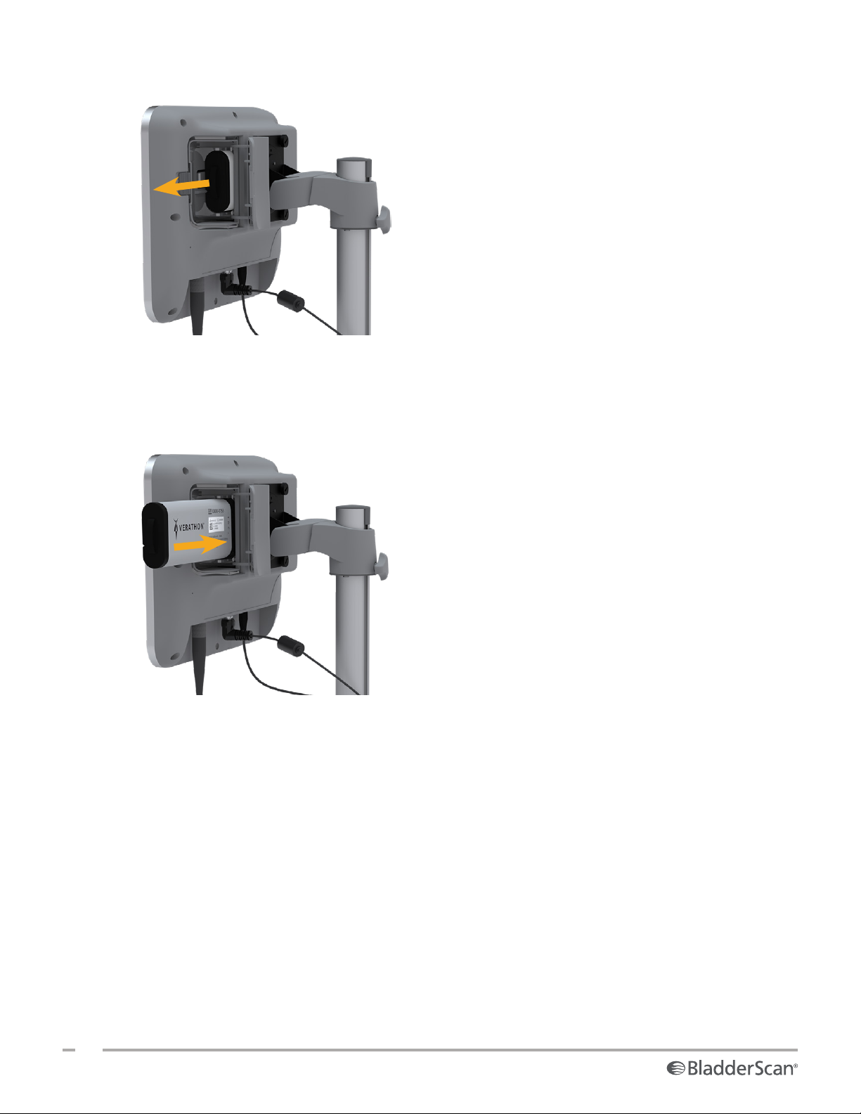
3. If a battery is already in the console, remove it by pulling the strap.
4. Slide a charged battery into the battery well, and then push gently until the battery is completely seated.
Note: The battery is designed to prevent incorrect installation. If the battery does not slide into the
battery well easily, remove the battery, reorient it, and try again. Do not attempt to force the battery into
position.
5. Close and latch the battery well door.
24
0900‑5005 REV‑00
Page 33
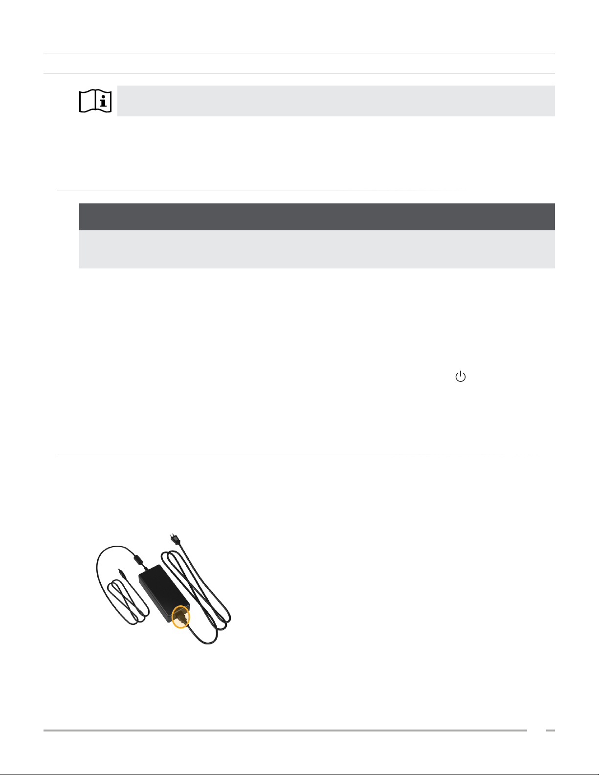
PROCEDURE 4. CHARGE THE BATTERY
Read the “Warnings & Cautions” section before performing the following task.
One lithium‑ion battery is included with the system. Before using the system for the first time, you must fully
charge the battery.
OPTION 1. CHARGING THE BATTERY IN THE CONSOLE
IMPORTANT
The probe does not operate when the system is connected to external (mains) power. To scan patients,
the console must have a charged battery and the system must be unplugged from external power.
1. Before each use, inspect the battery, the power adapter, and the power cord for damage. If a component
is damaged, do not use it. Contact Verathon CustomerCare or your local representative.
2. Make sure the power cable is securely connected to the console.
3. Plug the power adapter into a standard wall outlet. Make sure the power cord can be easily disconnected
if necessary.
4. If the battery indicator LED on the console remains unlit, press the On/Off button . The LED should
light up to indicate that the battery is charging.
5. Allow the battery to charge completely. The first charge should take about 3 hours.
OPTION 2. CHARGING WITH THE EXTERNAL CHARGER (OPTIONAL)
1. Before each use, inspect the battery charger, the battery or batteries, the power adapter, and the power
cord for damage. If a component is damaged, do not use it. Contact Verathon CustomerCare or your
local representative.
2. Connect the power adapter to the power cord.
Operations & Maintenance Manual: Setting Up
25
0900‑5005 REV‑00
Page 34
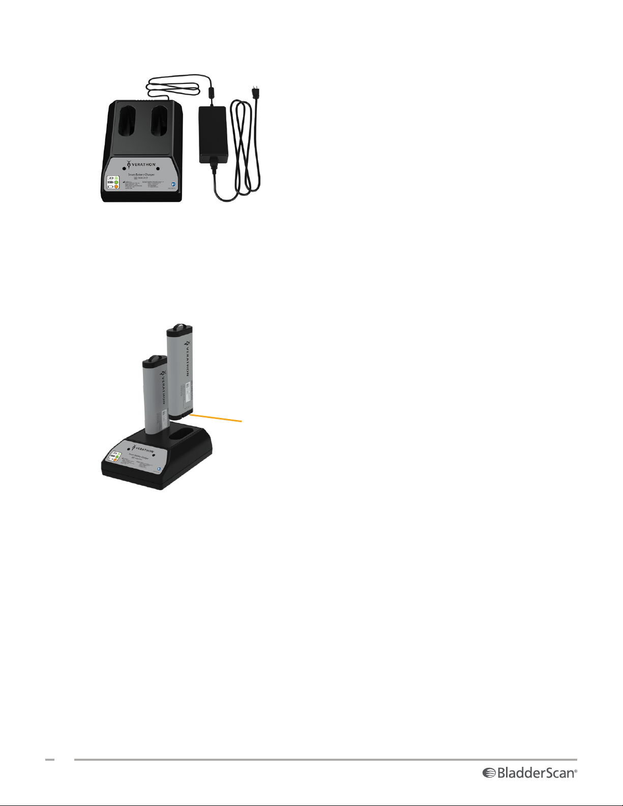
3. Connect the power adapter to the battery charger.
4. Plug the power adapter into a standard wall outlet. Make sure the power cord can be easily disconnected
if necessary.
5. Insert one or two batteries into the recesses in the battery charger. If you are charging two batteries for
the first time, charge both batteries at the same time for best results.
Note: To ensure that each battery is properly connected to the charger, make sure that its Verathon logo
and its contacts face right as seen from the front of the charger.
Battery contacts
6. Allow the battery to charge completely. The indicator lights on the battery charger indicate the status of
each battery:
• Green solid—Battery is fully charged
• Green flashing—Battery is charging
• Yellow solid—Battery charging is suspended or in standby mode
• Red—Charging error. Contact Verathon CustomerCare or your local representative.
• Off—No battery detected
26
0900‑5005 REV‑00
Page 35

PROCEDURE 5. INSTALL THE PRINTER (OPTIONAL)
An optional printer is available for BladderScan i10 systems. This printer is mounted on the base of the
workstation and communicates with the console through a standard USB connection.
If your organization has purchased the printer as part of its initial BladderScan i10 system order, follow the
instructions in the BladderScan i10 Workstation Assembly Quick Start Sheet (part number 0900‑5007) to
install the printer as you assemble the workstation.
If your organization purchases a printer for an existing BladderScan i10 system, follow the instructions in
the BladderScan i10 Printer Installation Quick Start Sheet (part number 0900‑5068) to add the printer to the
workstation and install the USB cable between the console and the printer.
Operations & Maintenance Manual: Setting Up
27
0900‑5005 REV‑00
Page 36
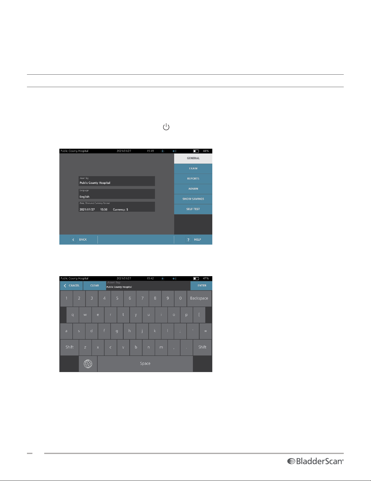
CONFIGURING SETTINGS
The system is configured with default settings that are appropriate for many users. This section contains
instructions for modifying the settings for your facility’s needs.
PROCEDURE 1. CONFIGURE GENERAL SETTINGS
This procedure helps you configure your regional and facility preferences, such as an asset tag for your
system, the language in which the system operates, and your formatting preferences for the time, date,
currency, and numbers.
1. If necessary, press the On/Off button . After a few seconds, the console displays the Home screen.
2. On the Home screen, tap Settings. The Settings screen opens to the General tab.
3. On the General tab, tap A sse t Tag. Use the virtual keyboard to type an identifying name or number, and
then tap Enter. The text you entered is displayed on the status bar at the top of each screen.
4. If you would like to change the language in which the system operates and exams are saved, tap
Language, and then select an available option. The language updates immediately.
28
0900‑5005 REV‑00
Page 37
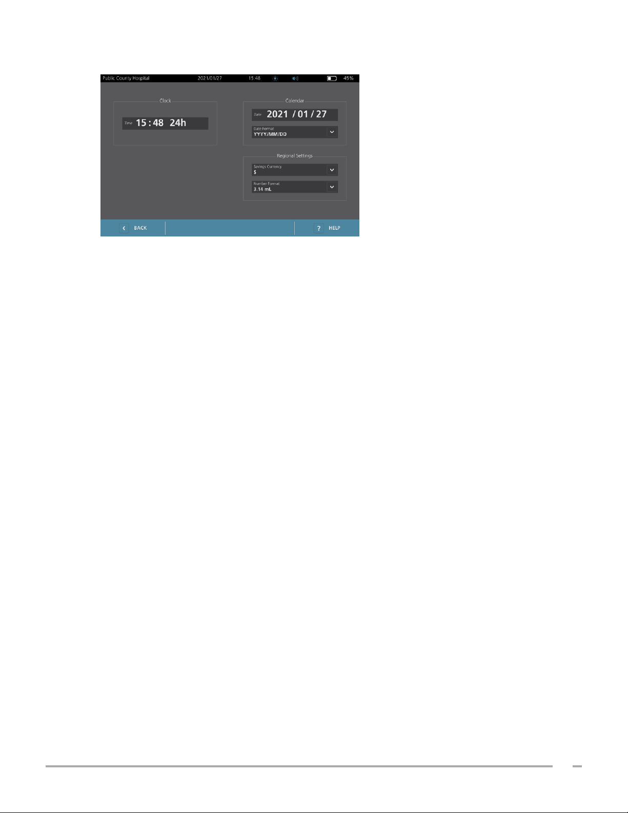
5. Tap Date, Time and Currency Format. The Date, Time and Currency screen appears.
6. In the Time field, tap the hour or minutes, vertically swipe to view a value, and then tap the value to
select it.
7. In the Time field, tap the time format. The time format scrolls through AM, PM, and 24‑hour displays. If
you select a new time format, the hours and minutes values are updated as necessary.
8. In the Date field, tap the month, day or year, vertically swipe to view a value, and then tap the value to
select it. Repeat as needed to set the desired month, day, and year.
9. In the Date Format field, tap the arrow, and then select the month, day, and year display order. The
Date field immediately updates to display the selected format.
10. In the Savings Currency field, tap the arrow and then select the desired currency. This unit is used when
displaying savings as a result of using the BladderScan system instead of catheterization.
11. In the Number Format field, tap the arrow to select the display format for numeric fields.
12. When you are finished configuring the Date, Time, and Currency settings, tap Back twice. This saves your
settings and returns the console to the Home screen.
Operations & Maintenance Manual: Setting Up
29
0900‑5005 REV‑00
Page 38
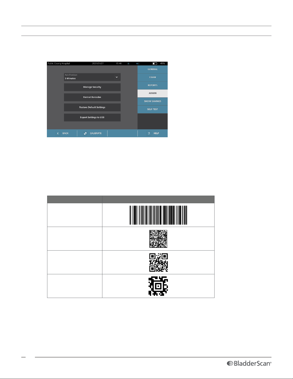
PROCEDURE 2. CONFIGURE ADMINISTRATIVE SETTINGS
1. On the Home screen, tap Settings, then Admin.
2. If a keypad appears, key in the PIN for Settings, and then tap Enter.
3. On the Admin tab, in the Auto‑Shutdown field, tap the arrow and then select the number of minutes
the system should remain on but inactive before it turns itself off.
Note: If an exam is in progress when automatic shutdown begins, the system saves the exam results.
4. If you want to define the type of barcode the system should use to display exam results, tap Format
Barcodes.
5. From the Format Symbology list, select one of the following barcode types.
SYMBOL TYPE EXAMPLE
Code 128
Data Matrix
QR Code
Aztec Code
30
0900‑5005 REV‑00
Page 39

6. From the Encoded Value list, select the amount of information to include in the barcode for each exam.
Where the selection allows it, a > symbol precedes the measured volume if the bladder extends outside
the scan area or if the pubic bone obstructs a portion of the bladder.
SELECTION INFORMATION INCLUDED EXAMPLE
A short phrase containing the
200 mL of urinary
bladder volume recorded
at 2:33 PM, 2020/04/22.
Full Exam Notes
measured volume (including the
> symbol if needed), the date,
the time, and the identity of the
system that created the scan
The measured volume in mL
Volume & Edge/Interference
(including the > symbol if
200 m L
needed)
A number representing the
measured volume in mL. This
Volume Number Only
selection allows numeric digits
200
only, so the > symbol is not
included.
Note: The Full Exam Notes option is not available if the Code 128 format is selected.
7. From the Prefix and Suffix boxes, select the control characters that the system should add before and
after the information:
• Carriage Return
• Line Feed
• Carriage Return & Line Feed
• Tab
• None
If necessary, contact the administrator of your facility’s EHR or EMR system to verify what control
characters the system needs.
8. When you are finished configuring settings, tap Back twice. This saves your settings and returns the
console to the Home screen.
Operations & Maintenance Manual: Setting Up
31
0900‑5005 REV‑00
Page 40
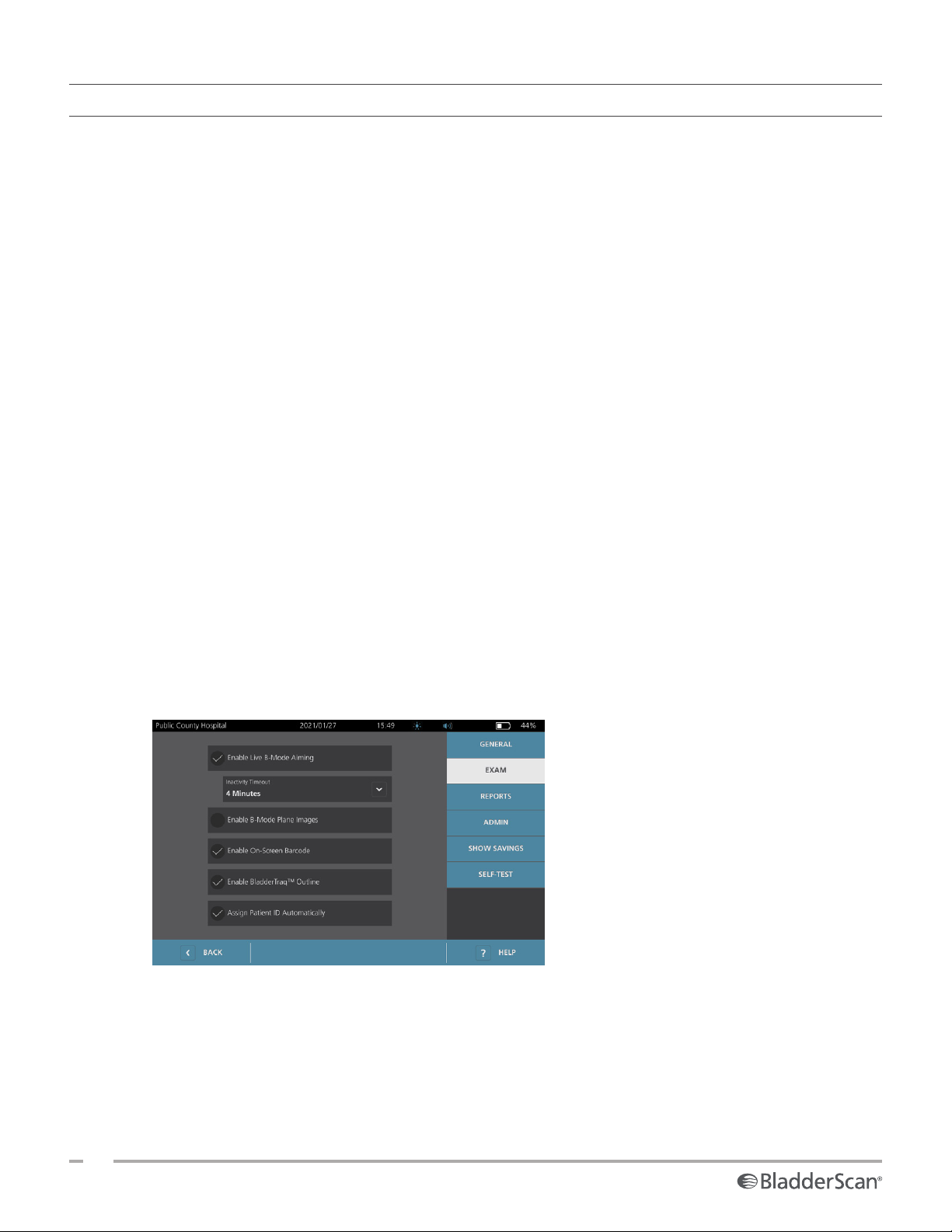
PROCEDURE 3. CONFIGURE EXAM SETTINGS
You may configure these exam settings:
• Display of B‑Mode images
• Live B‑mode aiming
• Time‑out interval for the live B‑mode aiming feature
• Bladder outline on B‑mode images
• Display of exam results in barcode format
• Assignment of an automatically generated patient ID number at the beginning of each exam
1. On the Home screen, tap Settings, and then tap Exam.
2. If a keypad appears, key in the PIN for Settings, and then tap Enter.
3. On the Exam tab, tap the field to update, and then if applicable, select or type the new value:
• Enable Live B‑Mode Aiming—Activates a real‑time, B‑mode ultrasound preview of the bladder
before the scan to provide aiming assistance.
• Inactivity Timeout—Defines the amount of time that live B‑mode aiming is active. Once the timeout
period has been reached, the system returns to the Home screen. This setting is only visible if live
B‑mode aiming is enabled.
• Enable B‑Mode Plane Images—Allows the display of B‑mode images in active and saved exams.
• Enable On‑Screen Barcode—Displays a patient’s exam results as a barcode, in addition to the
readable numbers the system normally displays.
• Enable BladderTraq™ Outline—On B‑mode images, displays a green outline around the detected
edges of the bladder.
• Assign Patient ID Automatically—Automatically generates a new patient ID for each exam. You
can replace this ID at the beginning of an exam, as described in the section “Input Patient Information
or Operator ID (Optional)” on page38.
4. When you are done, tap Back. This saves your settings and returns the console to the Home screen.
32
0900‑5005 REV‑00
Page 41
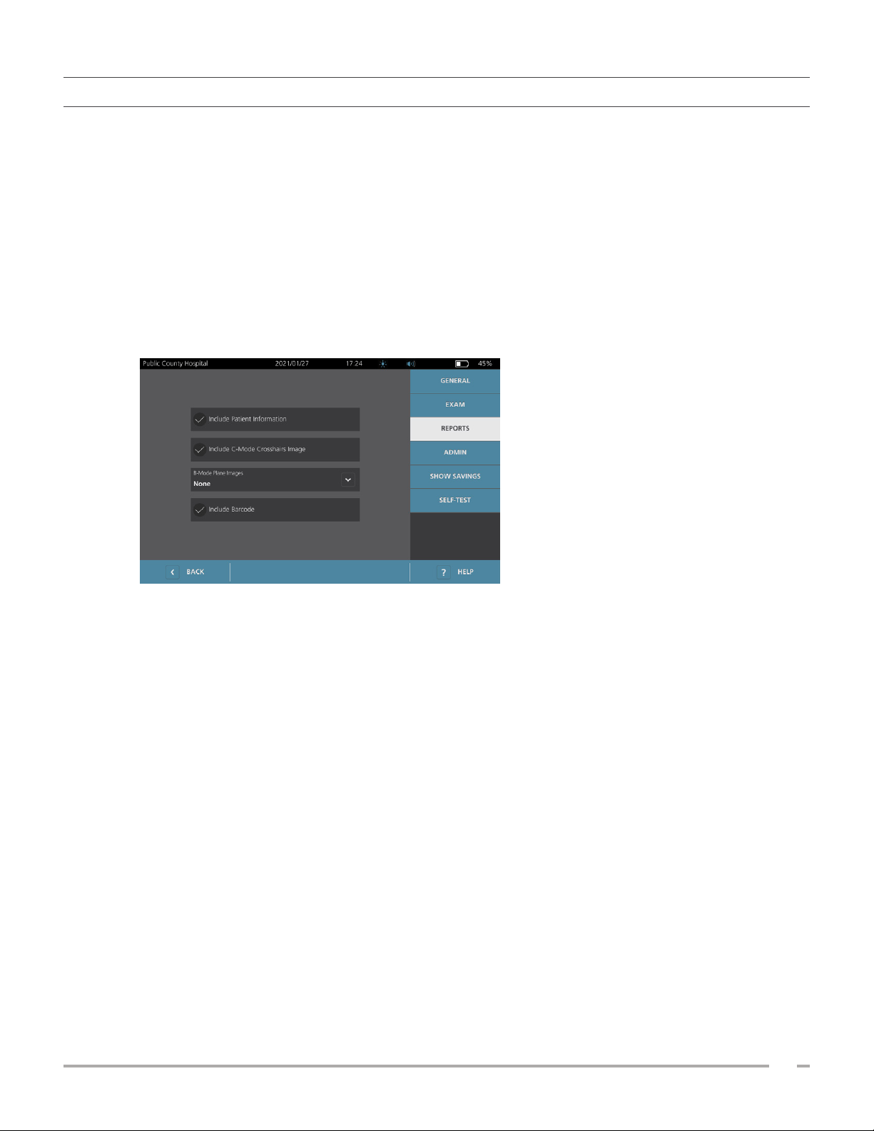
PROCEDURE 4. CONFIGURE PRINTED AND PDF REPORT SETTINGS
If a printer is attached to the console, you can print scan results. Reports are printed vertically, like a receipt.
Scan reports are made up of a number of sections. Some of the sections are optional.
You can also export saved exams to an external USB drive. For information on exporting exams, see “Export
Saved Exams” on page49.
You can customize which sections and B‑mode images are included in reports, regardless of whether they
are printed or exported in PDF format.
1. On the Home screen, tap Settings, and then tap Reports.
2. If a keypad appears, key in the PIN for Settings, and then tap Enter.
The Settings screen opens to the Reportstab.
3. Tap the information to include in reports. If a check mark is displayed to the left of the information
description, the following information is printed:
• Include Patient Information—Select to include patient data, such as patient ID or date ofbirth.
• Include C‑Mode Crosshairs Image—Select to include the coronal view image computed by the
system. The aiming circle and crosshairs are printed as black lines.
• B‑Mode Plane Images—Select one of the following groups of images to include in printed and
exported reports:
○ None—Select to include no B‑mode image planes.
○ All—Select to include all 12 B‑mode image planes.
○ Sagittal & Transverse—Select to include the two primary B‑mode image planes.
• Include BladderTraq™ Outline—Select to add outlines of the bladder’s internal contours to the
B‑mode image.
• Include Barcode—Select to include the exam’s final volume measurement as a barcode.
4. When you are finished configuring the printed report settings, tap Back. This saves your settings and
returns the console to the Home screen.
Operations & Maintenance Manual: Setting Up
33
0900‑5005 REV‑00
Page 42
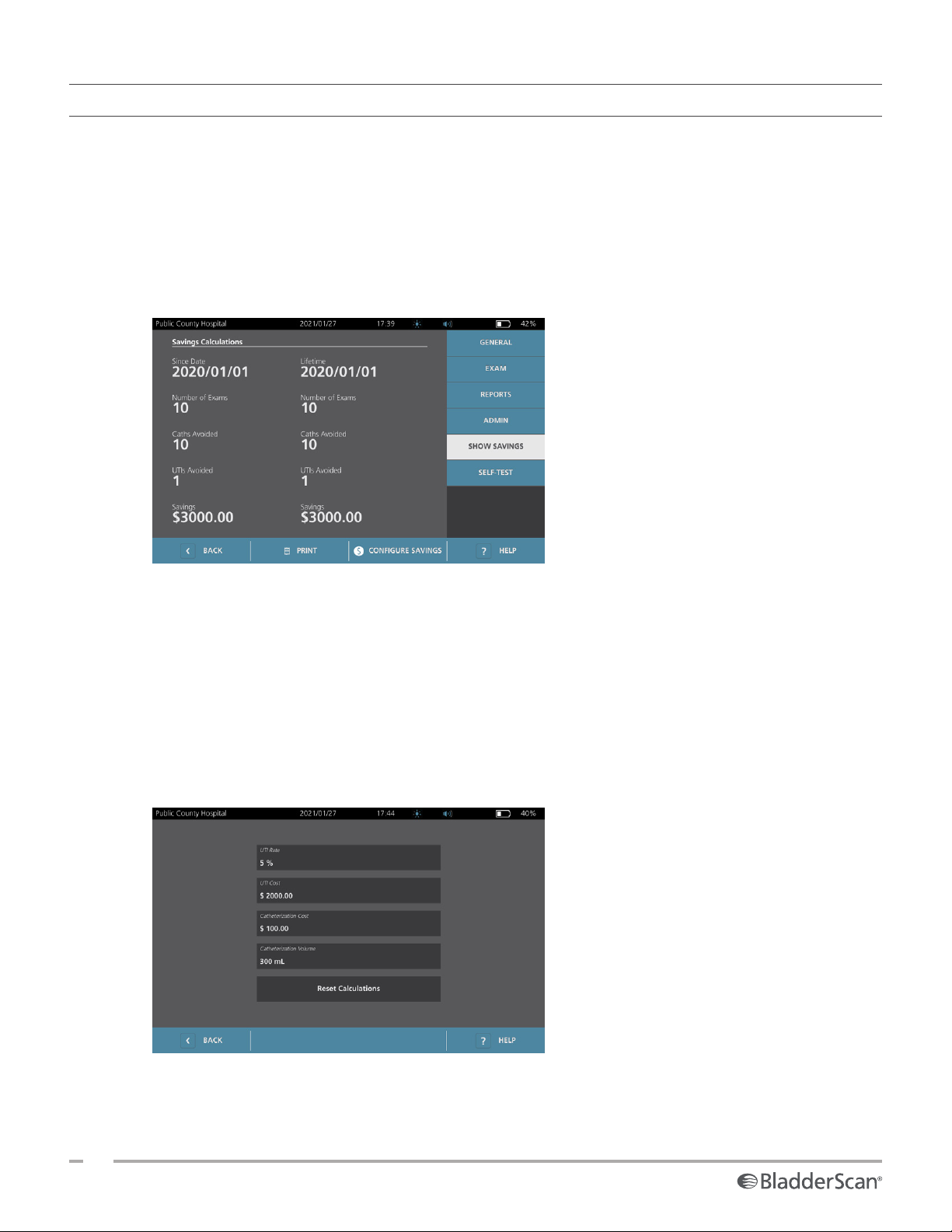
PROCEDURE 5. CUSTOMIZE COST SAVINGS CALCULATIONS
The system provides default values for calculating the cost savings that result from scanning rather than
catheterizing patients. The default settings can be customized to reflect the rates and costs at your facility. To
change the currency used for cost savings calculations, see “Configure General Settings” on page28.
Total cost savings from using the system are based on this formula:
Total cost savings = (Catheterizations avoided × Catheterization costs) + (UTIs avoided × UTI costs)
1. On the Home screen, tap Settings, and then tap Show Savings.
2. On the Show Savings tab, tap Configure Savings.
3. On the Configure Savings screen, tap a field to update, and then enter new values. Numeric fields accept
decimal input but round to the nearest whole number.
• UTI Rate—Select the rate of urinary tract infections (UTIs) resulting from catheterizations.
• UTI Cost—Select the cost per UTI at your facility.
• Catheterization Cost—Select the cost per catheterization procedure.
• Catheterization Volume—Select the volume threshold for catheterization. Scans below the volume
threshold are not used in cost savings calculations.
Note: The Reset Calculations button restarts savings calculations as of the date this button is selected.
Tapping this button is not required to update savings values.
4. When you are finished, tap Back twice. This saves your settings and returns the console to the Home
screen.
34
0900‑5005 REV‑00
Page 43
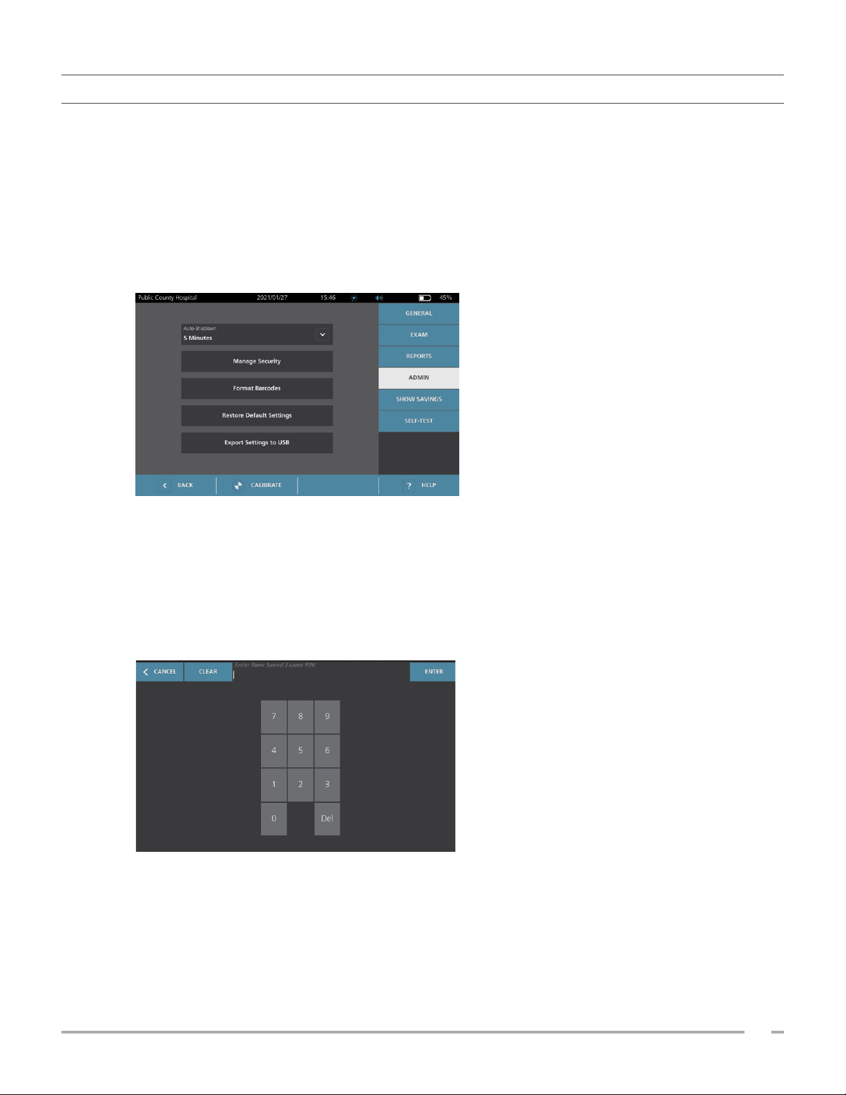
PROCEDURE 6. CONFIGURE A PIN FOR SAVED EXAMS
If it is necessary to restrict access to saved patient and exam information, you can create a PIN to protect that
information. After you create the PIN, the system does not display saved exams unless the PIN is entered.
Deleting the PIN deactivates this requirement.
If you need to change the PIN, you must enter the existing PIN before you create the new one.
1. At the Home screen, tap Settings.
2. At the Settings screen, tap the Admin tab.
3. If a keypad appears, key in the PIN for Settings, and then tap Enter.
4. On the Admin tab, tap Manage Security.
5. In the Manage Security dialog box, tap Change PIN for Saved Exams.
6. Tap the Enter New Saved Exams PIN box. Using the keypad, key in the new 4‑digit PIN required for
access to saved exams on the system, and then tap Enter.
Alternatively, to deactivate the PIN for Saved Exams, tap Clear to remove any digits that have already
been entered. Save the change by tapping Enter.
7. Tap the Confirm New Saved Exams PIN box, and then enter the same code you entered previously.
8. Tap Save PIN for Saved Exams.
Operations & Maintenance Manual: Setting Up
35
0900‑5005 REV‑00
Page 44
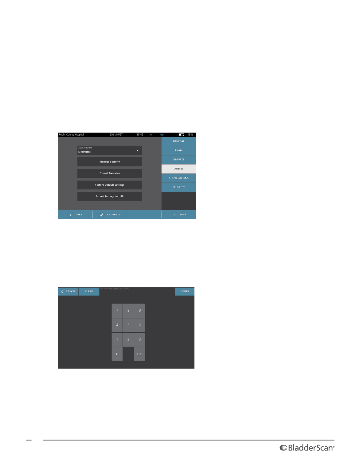
PROCEDURE 7. CONFIGURE A PIN FOR SYSTEM SETTINGS
If it is necessary to ensure that system configuration settings are consistent throughout your organization,
you can create a PIN to restrict people from changing the settings on the Admin, Exam, and Reports tabs or
resetting the system to factory defaults. Deleting the PIN for Settings makes these items available to anyone.
If you need to change the PIN for Settings, you must enter the existing PIN before you create the new one. If
you have forgotten the existing PIN, contact Verathon Customer Care for assistance in clearing it.
1. At the Home screen, tap Settings.
2. At the Settings screen, tap the Admin tab.
3. If a keypad appears, key in the PIN for Settings, and then tap Enter.
4. On the Admin tab, tap Manage Security.
5. In the Manage Security dialog box, tap Change PIN for Settings.
6. Tap the Enter New Settings PIN box. Using the keypad, key in the new 4‑digit PIN required for access
to system settings, and then tap Enter.
Alternatively, to deactivate the PIN for Settings, tap Clear to remove any digits that have already been
entered. Save the change by tapping Enter.
7. Tap the Confirm New Settings PIN box, and then enter the same code you entered previously.
8. Tap Save PIN for Settings.
36
0900‑5005 REV‑00
Page 45
USING THE SYSTEM
Read the “Warnings & Cautions” section before performing the following tasks.
MEASURING BLADDER VOLUME
PROCEDURE 1. PREPARE FOR THE EXAM
Make sure you are familiar with the console’s icons and screens. For more information about the system
components and user interface, see the chapter “Introduction” on page9.
1. If a charged battery is inserted in the console and the touchscreen is blank, then the system is turned off.
Press the On/Off button .
If the system has a discharged battery or a battery is not inserted, insert a charged battery.
Note: Before you insert a battery into the console, press the Test button and make sure the battery is
fully charged. If the charge level in the battery is 20% full or less, replace it with a fully charged battery
before proceeding. The system cannot perform an exam while it is connected to external power.
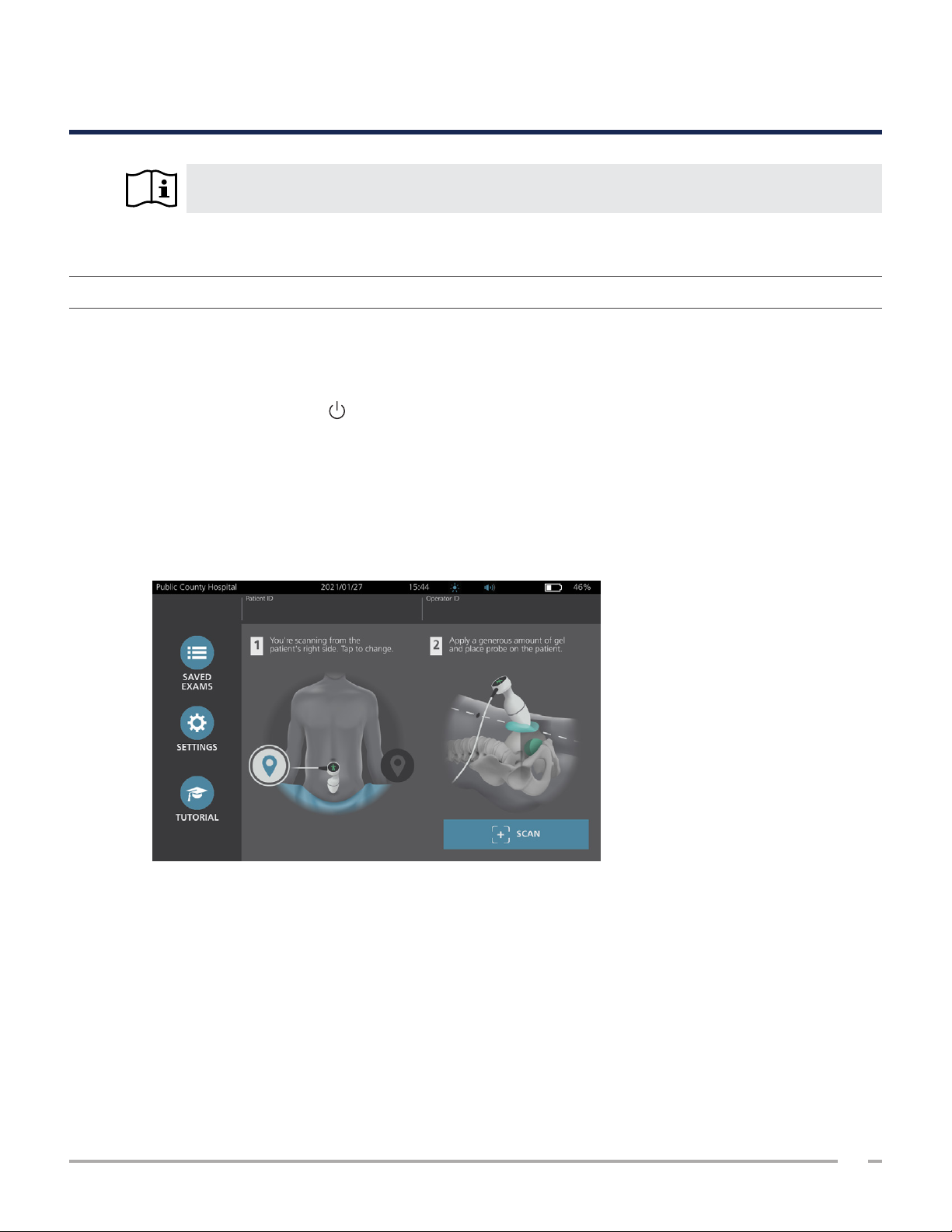
2. Allow the system to start. When the system has started completely, the Home screen appears as shown
in the following figure.
3. Check the battery icon to make sure the battery has sufficient power.
4. Make sure the system has been properly cleaned according to the instructions in the “Reprocessing”
chapter on page50. In particular, make sure that the touchscreen is not contaminated by gel, cleaner,
disinfectant, or any other residue, and that it is completely dry.
Operations & Maintenance Manual: Using the System
37
0900‑5005 REV‑00
Page 46
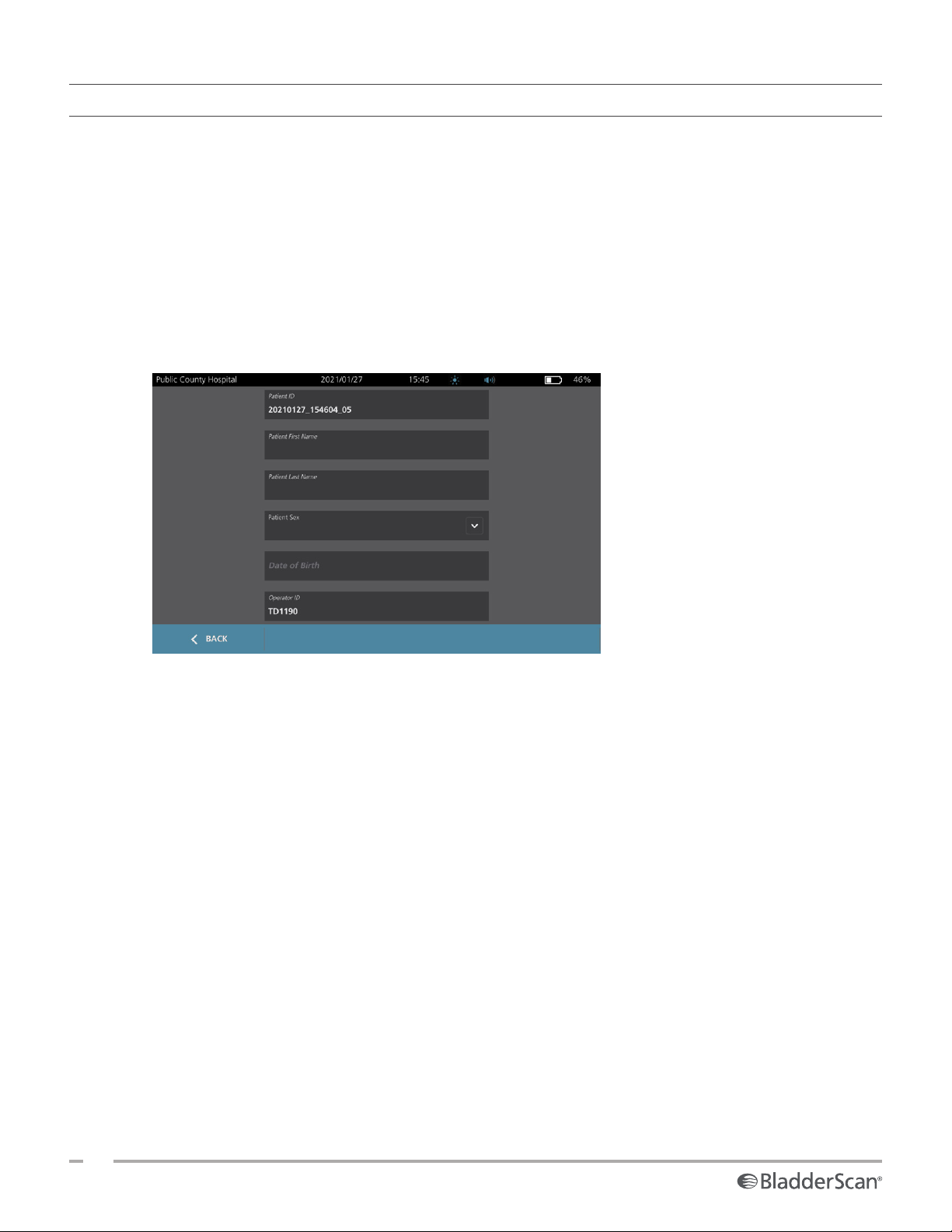
PROCEDURE 2. INPUT PATIENT INFORMATION OR OPERATOR ID (OPTIONAL)
The system lets you enter the following patient information, which will be saved with the exam and can be
printed on the exam report:
• Patient ID
• First name
• Last name
The Operator ID may also be updated at this time. The Patient ID and Operator ID fields are displayed at the
top of many screens. You can tap the field and update Patient or Operator ID information whenever the field
is visible.
1. On the Home screen, tap Patient ID. The Patient and Operator ID screen appears.
• Sex
• Date of birth
2. On the Patient Data screen, tap Patient ID, use the virtual keyboard to type a value, and then tap Enter.
3. Tap Patient First Name, and then enter the patient’s first name.
4. Tap Patient Last Name, and then enter the patient’s last name.
5. Tap Patient Sex, and then tap the sex for the patient.
6. Tap the Date of Birth field, vertically swipe to change a value, and then tap the new value to select it.
Repeat as needed to set the desired month, day, and year.
7. Tap Operator ID, and then use the virtual keyboard to enter or update the operator’s identifying
information.
8. When you are finished inputting the patient’s information, tap Back.
38
0900‑5005 REV‑00
Page 47
PROCEDURE 3. MEASURE BLADDER VOLUME
The system has several features designed to help with locating and identifying the bladder. These features
may be enabled or disabled according to the instructions in “Configure Exam Settings” on page32:
• Live B‑Mode Aiming—The system displays a real‑time B‑mode ultrasound view of the patient’s
abdomen, allowing you to aim the probe and locate the bladder before scanning.
• Bladder Outline (BladderTraq)—In B‑mode views, the system highlights the detected edges of the
bladder by outlining the bladder area in green.
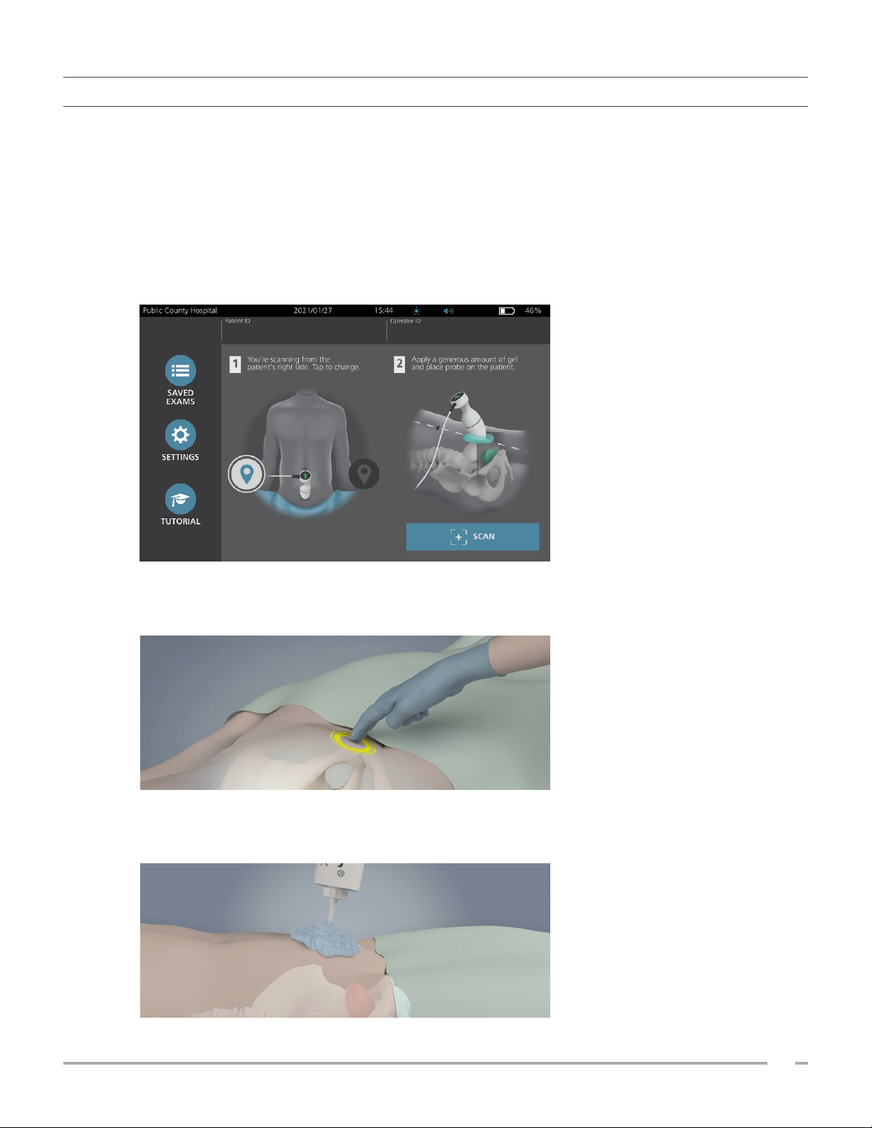
1. On the Home screen, select whether you are standing on the patient’s left or right side. You do not need
to specify the patient’s age or sex to obtain an accurate result.
2. With the patient lying in a supine position and with the abdominal muscles relaxed, palpate the patient’s
pubic bone.
3. Place an ample quantity of ultrasound gel, with as few air bubbles as possible, midline on the patient’s
abdomen, approximately 3 cm (1 inch) above the pubic bone.
Operations & Maintenance Manual: Using the System
39
0900‑5005 REV‑00
Page 48
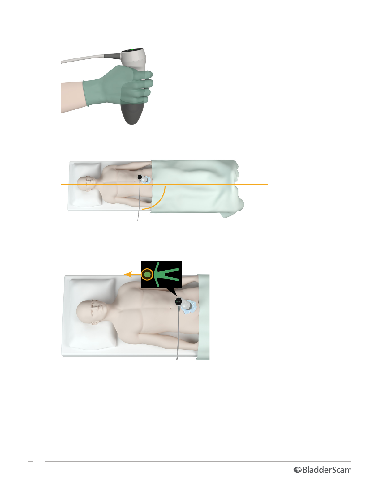
4. Hold the probe by grasping it with the probe cable running up your wrist and forearm.
5. Gently press the probe onto the lower abdomen through the gel. The probe cable should be oriented at
90degrees to the sagittal plane of the patient.
Sagittal plane
90°
Probe cable
6. Look at the position indicator icons on the top of the probe. Make sure the head of the lighted direction
indicator points in the same direction as the head of the patient.
7. If you are scanning an obese patient, lift as much abdominal adipose tissue out of the way of the probe
as possible. Apply more pressure to the probe to reduce the amount of adipose tissue through which the
ultrasound must pass, but use no more pressure than necessary.
8. Make sure that there are no air gaps between the probe and the patient’s skin, and that you are applying
enough pressure to maintain adequate skin contact, until the scan is complete. If necessary, add more
gel to ensure proper contact.
40
0900‑5005 REV‑00
Page 49
9. Press the probe button or tap Scan on the Home screen.
• If live B‑mode aiming is enabled, continue to Step 10.
• If live B‑mode aiming is disabled, hold the probe steady while the scan is in process, and then
continue to the procedure “Review Exam Results”.
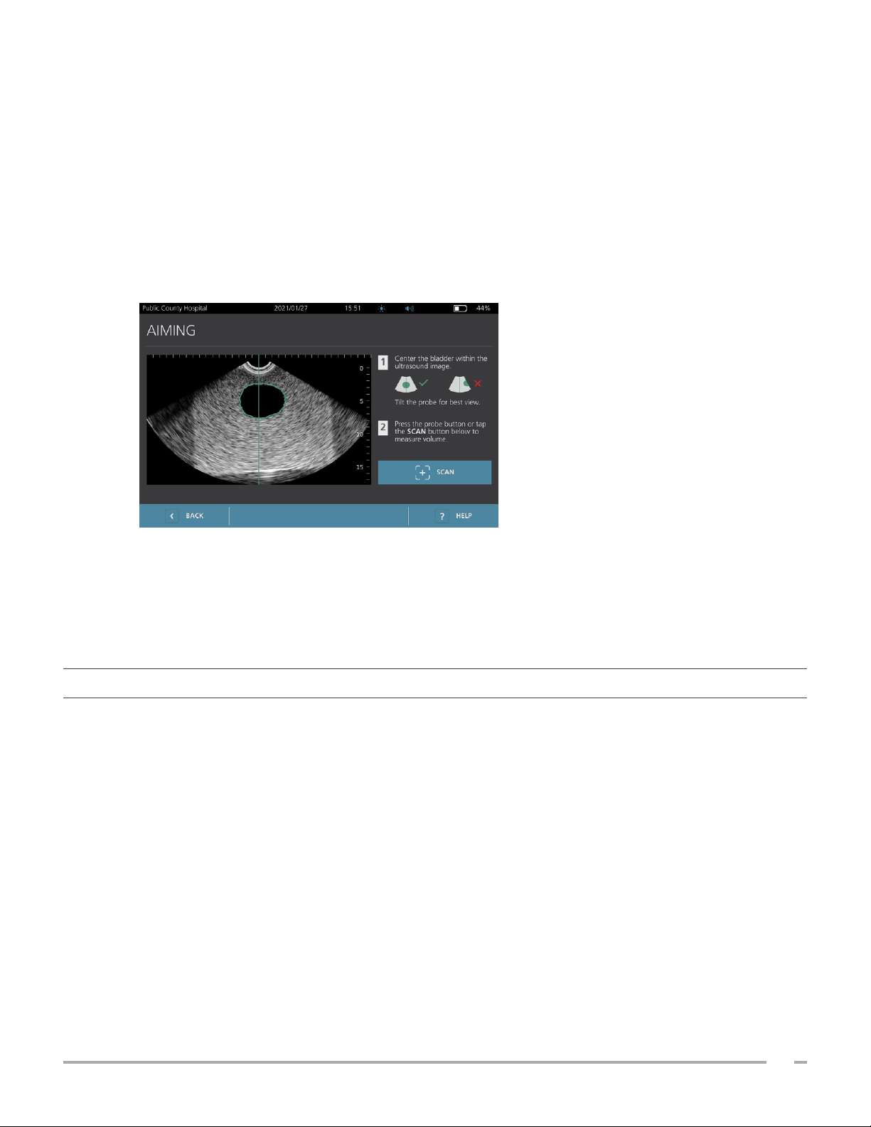
10. If live B‑mode aiming is enabled, a real‑time B‑mode ultrasound image appears on the console screen.
Target the bladder by doing the following:
• Angle the probe slowly from the patient’s left to right until the dark (bladder) area is centered on the
vertical green line on the aiming screen.
• Once the bladder is centered, angle the probe slightly up or down the patient’s midline to obtain the
largest possible dark area.
11. Once you are finished aiming the probe, press the probe button or tap Scan on the screen. The scanning
process begins.
12. Hold the probe steady while the scan is in process. When you hear the end‑scan tone, the scan is
complete. Continue to the procedure “Review Exam Results”.
PROCEDURE 4. REVIEW EXAM RESULTS
This section describes the procedures that can occur after the scan. Perform the procedures that are
applicable for your installation.
CONFIRM OR ADJUST AIM
Aiming technique can have an impact on the bladder measurement result. When the bladder is partially
outside the ultrasound field of view or obstructed by the pubic bone at certain scanning angles, then the
actual bladder volume may exceed the displayed result. To help ensure the highest degree of accuracy, the
system has several features to assist with aiming technique and confirmation.
Operations & Maintenance Manual: Using the System
41
0900‑5005 REV‑00
Page 50
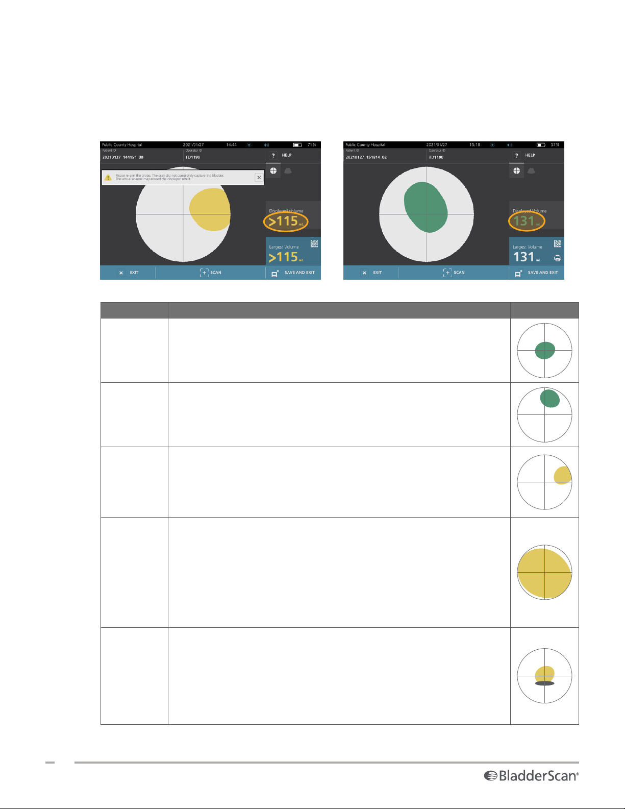
1. When the Results screen appears, check whether a yellow greater than (>) symbol appears next to the
recorded volume and the bladder is shown in yellow. If this occurs, a portion of the bladder was outside
the ultrasound field of view, and the actual bladder volume may exceed the displayed result. You should
aim the probe again and rescan the patient. For guidance on improving the scan results, see Table 9.
Figure 5. Greater Than (>) Symbol
Displayed
Figure 6. Greater Than (>) Symbol
Not Displayed
Table 9. Bladder Measurement Accuracy
RESULT AIMING GUIDANCE EXAMPLE
Successfully
Centered
Not
Centered
If the bladder is centered in the field of view, with all edges visible and
no gray areas showing, then the scan was successful and the results are
as accurate as possible.
If the bladder is not centered in the field of view, you may move or angle
the probe in the direction of the bladder on the display to optimize your
results.
EdgeScan
Bladder
larger than
view
Pubic bone
interference
If one side of the bladder is not within the field of view, then a portion of
the bladder was not included in the scan. The system displays a greater
than symbol (>) before the measured result, indicating the actual bladder
volume may exceed the displayed result. Move or angle the probe in the
direction of the bladder on the display to optimize your results.
If more than one side of the bladder is not within the field of view, then
multiple portions of the bladder were not included in the scan. The
system displays a greater than symbol (>) before the measured result,
indicating the actual bladder volume may exceed the displayed result.
You may attempt to capture the entire bladder by rescanning while
applying less pressure to the abdomen. However, the bladder may be
larger than the field of view, and it may not be possible to capture the
entire bladder within the view.
If a gray area appears, this indicates that the pubic bone is inside
the field of view. Although the bladder may be centered and your
measurement may be complete, there is a possibility the pubic bone is
obscuring part of the bladder. The system displays a greater than symbol
(>) before the measured result, indicating the actual bladder volume
may exceed the displayed result. You may move or angle the probe to
optimize your results.
42
0900‑5005 REV‑00
Page 51
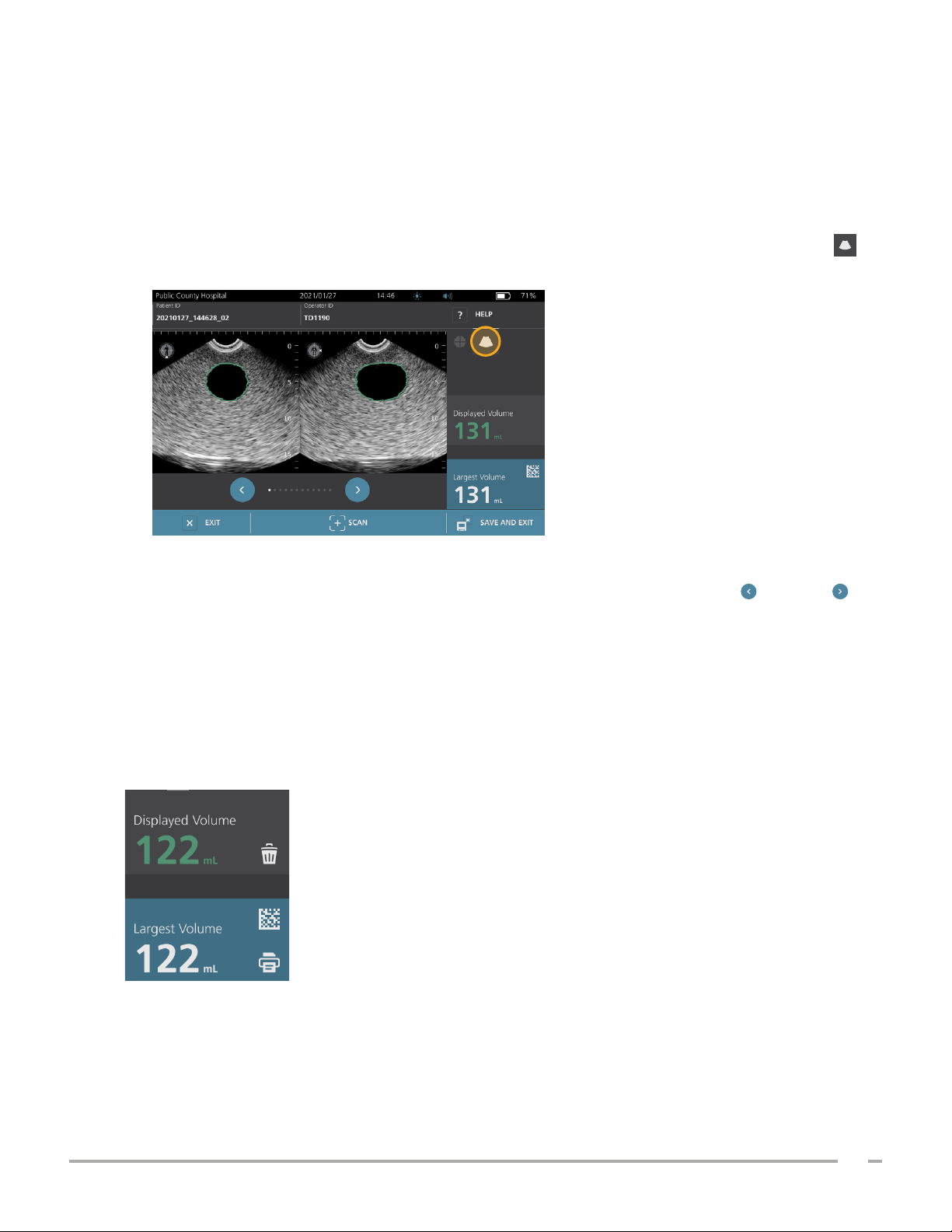
2. If you want to rescan the patient, on the Results screen, tap Scan.
Repeat the scanning procedure as necessary to adjust your aim or confirm the initial measurement.
3. When you are finished scanning, you can review the results in B or C modes. (C‑mode is displayed by
default.) You can save scan results, and you can print scan results if you have the printer installed.
VIEW B‑MODE IMAGES
4. If B‑mode images are activated on your system and you want to view them, tap the B‑mode icon .
Dual‑pane B‑mode images of the scan appear.
5. In the top‑left corner of each of the B‑mode images, the line through the human figure icon indicates
the currently displayed plane. To navigate through the scan planes, tap the Previous and Next
icons below the images.
VIEW MULTIPLE SCANS
When you perform more than one scan, the Results screen displays the largest volume obtained. Above the
largest volume measurement, the screen indicates the most recent scan volume.
Note: If you scan the patient more than five times during a single exam, the system stores only the five latest
scan volumes.
Operations & Maintenance Manual: Using the System
43
0900‑5005 REV‑00
Page 52
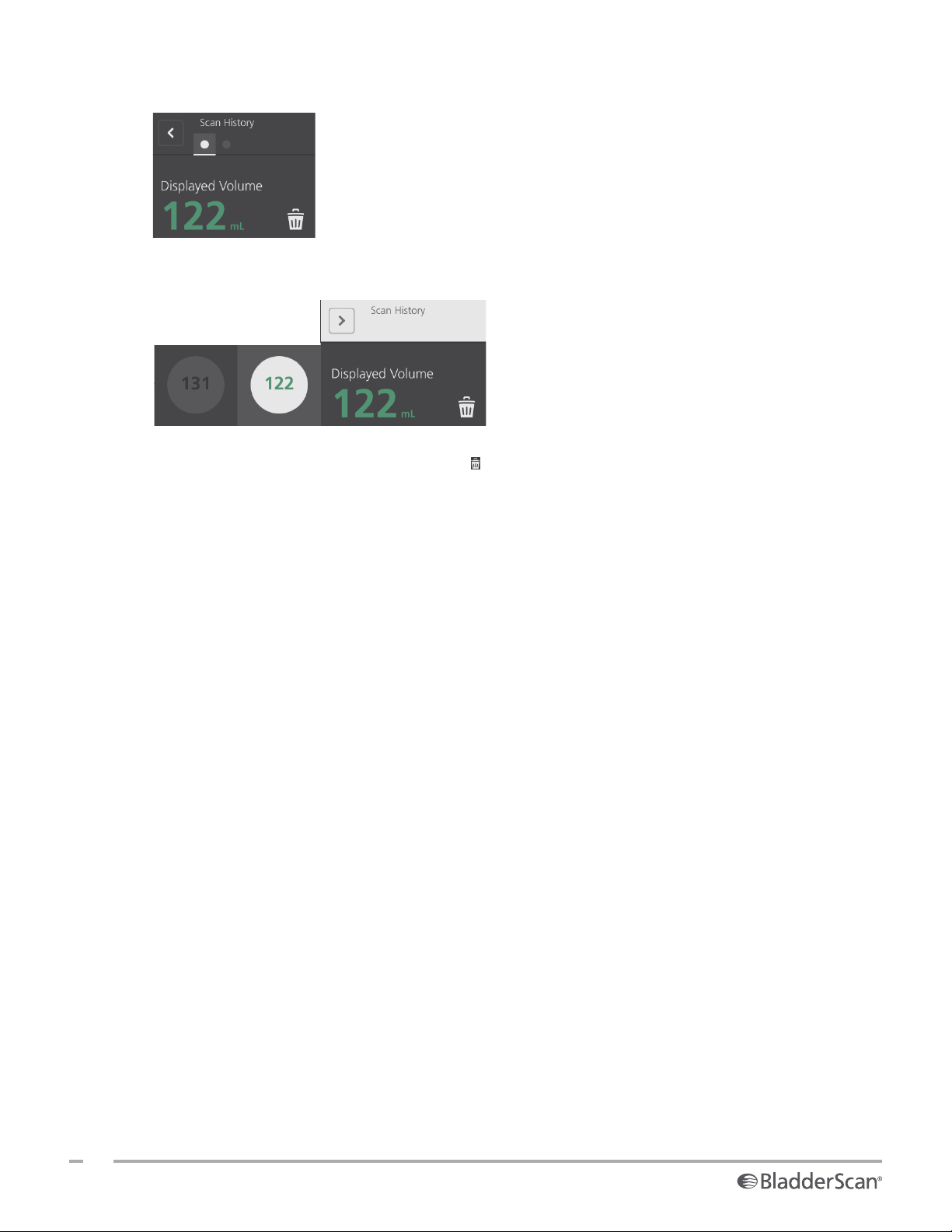
6. If you want to show individual scan measurements, tap the Scan History arrow.
7. Tap the scan measurement number to see the scan display.
8. To discard the displayed scan, tap the Delete icon.
9. If you want to transfer the scan result to an EHR or EMR system using a barcode reader, continue to the
procedure “Generate a Barcode containing an Exam Result”.
Otherwise, skip to the procedure “Print, Save, or Exit an Active Exam”.
44
0900‑5005 REV‑00
Page 53
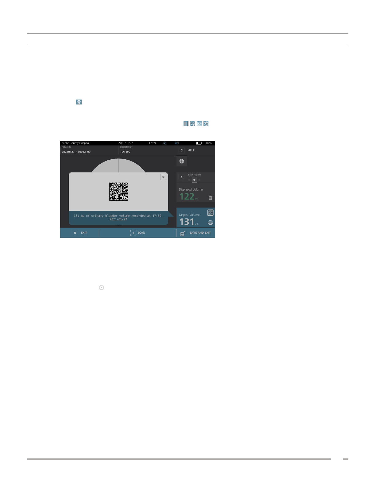
PROCEDURE 5. GENERATE A BARCODE CONTAINING AN EXAM RESULT
Once the system has been configured to generate barcodes, you can display a barcode containing the largest
scan result of the current exam on the console’s touchscreen. You can then use a barcode reader to collect
the scan result and transfer it to your facility’s medical records system (which can be either an EHR or an EMR
system).
If this feature is active, a barcode icon appears next to the largest scan result stored in the exam, just above
the Print icon. The exact appearance of the icon matches the type of barcode the system displays, which
is selected during configuration.
1. On the Results screen, tap the Barcode icon . The barcode, and a string of text showing the
exact result statement the barcode contains, appear in a dialog box on the screen.
2. On your medical records system, locate the patient’s record and select the field where bladder volume
should be stored.
3. Using a barcode reader connected to the medical records system, scan the displayed barcode.
4. Tap the Close icon in the dialog box to remove the dialog box from the screen.
Operations & Maintenance Manual: Using the System
45
0900‑5005 REV‑00
Page 54
PROCEDURE 6. PRINT, SAVE, OR EXIT AN ACTIVE EXAM
When the exam is complete, you can take several actions from the Results screen.
If you want to… Tap…
Record patient information Patient ID
Print the exam results Print
Save the exam results (the system stores the
largest measurement)
Exit without saving the exam results Exit
Note: A printed exam report always contains the largest measurement and the exam date and time, but you
can customize the remaining information in the report. For more information about adding and customizing
information to be printed, see “Configure Printed and PDF Report Settings” on page33.
Note: This is the last point in the scanning process where you can add or modify patient or operator
information. After you save the exam, patient or operator information cannot be changed.
For information about viewing, deleting, and exporting saved exams, see the section “Managing Saved
Exams” on page47.
Save and Exit
PROCEDURE 7. VIEW COST SAVINGS
The system calculates and displays information related to cost savings, catheterizations avoided, and UTIs
avoided. The default settings can be customized to reflect the rates and costs at your facility. For more
information on customizing savings preferences, see “Customize Cost Savings Calculations” on page34.
The system calculates savings since the most recent calculation reset and for the life of the system. You can
show, configure, and reset cost savings at any time.
1. On the Home screen, tap Settings.
2. Tap Show Savings. The Settings screen opens to the Show Savingstab.
3. If you have a printer and want to print the savings calculations, tap Print.
4. When you are finished viewing the savings calculations, tap Back. The console returns to the
Homescreen.
46
0900‑5005 REV‑00
Page 55
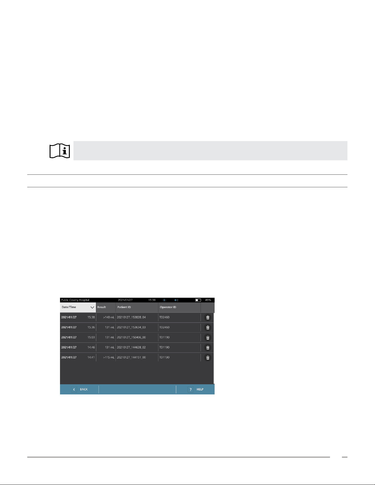
MANAGING SAVED EXAMS
The system can store saved exams in its internal memory or on external devices such as USB flash drives. If
you scan the patient multiple times during an exam, the system saves the largest measurement.
If no external devices are attached, the system stores saved exams in its internal memory. If the system runs
out of internal memory, it overwrites the oldest exams as needed to make space for new ones. The system is
capable of storing 600 exams within its internal memory.
If a USB drive is attached, the system stores saved exams on the USB drive. If an attached USB drive runs low
on space, the system notifies you so that you can switch drives.
You can move exams from the internal memory to an external USB drive. For more information, see the
procedure “Export Saved Exams” on page49.
Read the “Warnings & Cautions” section before performing the following tasks.
PROCEDURE 1. RECALL A SAVED EXAM
Once you have saved an exam, it can be recalled using the Saved Exams screen. The Saved Exams screen
displays exam results saved on the system’s internal memory if no external drives are attached. If a USB drive
is attached, the Saved Exams screen displays exam results saved on the attached drive.
If there are multiple scan results in an exam, the system saves only the largest measurement.
SORT OR SCROLL SCANS
1. On the Home screen, tap Saved Exams.
2. If a keypad appears, key in the PIN for Saved Exams, and then tap Enter.
The Saved Exams screen opens, displaying a list of exams saved on the default media. Each of the rows
on this list corresponds to an exam.
Operations & Maintenance Manual: Using the System
47
0900‑5005 REV‑00
Page 56
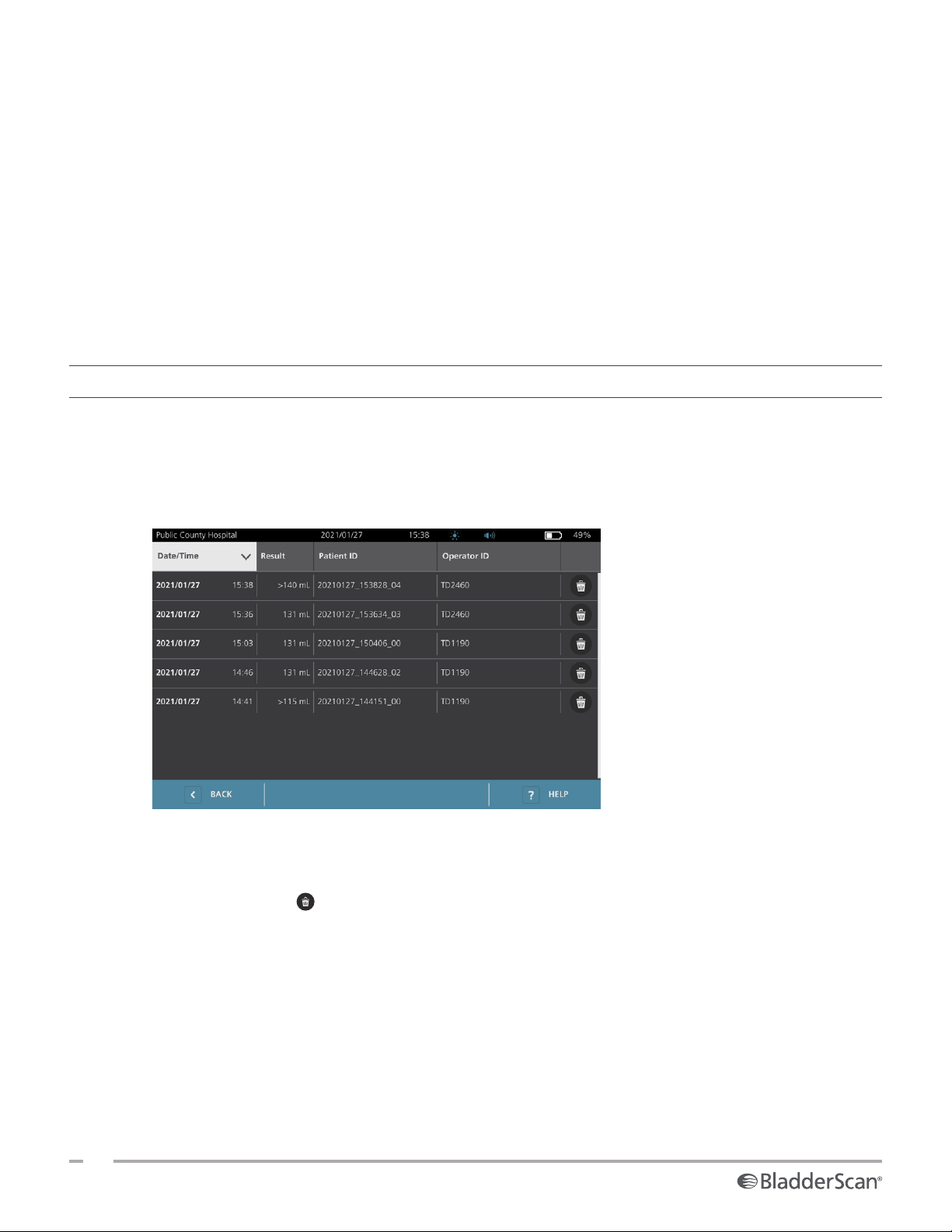
3. If you want to sort exams using a different value, tap a sortable field header.
The field headers let you sort the exam list using the following fields. The columns may be sorted in
ascending or descending order. The currently selected sorting field is highlighted in white, and an arrow
icon indicating the direction of the sort is shown next to the column label.
• Date/Time
• Patient ID
• Operator ID
4. If you want to scroll through the exam list, swipe the screen vertically (top to bottom or bottom to top).
5. If you want to view an exam, tap anywhere along the exam’s row. When an exam is selected for review,
the results screen for the exam is displayed.
PROCEDURE 2. DELETE A SAVED EXAM
1. On the Home screen, tap Saved Exams.
2. If a keypad appears, key in the PIN for Saved Exams, and then tap Enter.
The Saved Exams screen opens, displaying a list of exams saved on the default media. Each of the rows
on this list corresponds to an exam.
3. If it is not visible in the list, sort or scroll through saved exams to display the one you want. For more
information on finding exams, see “Recall a Saved Exam” on page47.
4. Tap the Delete icon at the right end of the exam row.
5. On the confirmation dialog box, tap Yes.
Note: You may also delete a saved exam that is currently being viewed. To delete an opened exam, at the
bottom of the screen, tap the Delete icon.
48
0900‑5005 REV‑00
Page 57
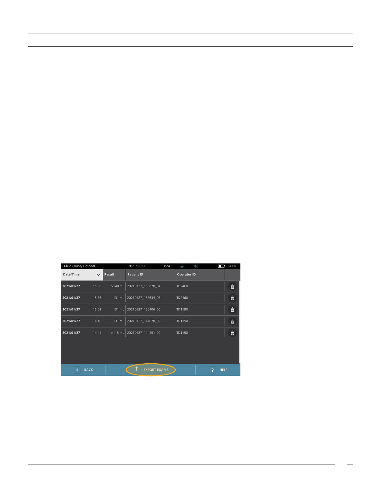
PROCEDURE 3. EXPORT SAVED EXAMS
Use this procedure to move exams from the system’s internal memory to an external USB drive.
By default, saved exam results are retained in the system’s internal memory. When you insert a USB drive into
the console, the system immediately begins reading the new drive for saved exam results. If no exams have
previously been saved to the external drive, the Saved Exams screen appears blank. However, exam results
in the system’s internal memory are not lost, and you can export them to the new drive. After exporting the
exams, the system removes them from its internal memory.
Exams are saved with unique file names, so that exporting new exams does not overwrite exams already
stored on the USB drive.
Exported exam information is stored in PDF format, so that it can be viewed on other devices. Each exam
document is stored in a separate folder on the USB drive and includes the following information:
• Patient information
• C‑mode view of the scan (if the C‑mode crosshairs image is enabled in reports)
• B‑mode views of the scan (if B‑mode images are enabled in reports)
1. Insert a USB drive into an available USB port on the console.
2. If the system displays a message advising you to check the USB drive for damage, remove the drive from
the port. Repeat Step 1 using a different USB drive.
3. On the Home screen, tap Saved Exams.
4. If a keypad appears, key in the PIN for Saved Exams, and then tap Enter.
5. On the Saved Exams screen, tap Export Exams.
6. On the verification screen that appears, tap YES to confirm you want to move exams stored on the
console to the USB drive. Do not remove the drive until export is complete.
Operations & Maintenance Manual: Using the System
49
0900‑5005 REV‑00
Page 58
REPROCESSING
Read the “Warnings & Cautions” section before performing the following tasks.
Cleaning and disinfecting the BladderScan i10 system is an important part of using and maintainingit.
Before each use, ensure all system components have been cleaned and disinfected according to the guidance
provided in Table 10.
Note: It is understood that all items in the following table will be used as intended.
Table 10. Reprocessing Requirements for the BladderScan i10 System
COMPONENT
Console
Probe Cable
Probe
Printer
Workstation
The reprocessing levels shown in this table refer to the CDC/Spaulding classifications.
Clean Low High
CLEANERS & DISINFECTANTS
DISINFECTION EFFICACY
Table 11 lists the low‑level disinfectant (LLD) classes that have demonstrated efficacy with the system. For
information about the long‑term effect of solutions on system materials, see “Compatibility”.
REQUIRED REPROCESSING LEVELS
Table 11. Validated Disinfectants
Alcohols (or alcohol with Quat) 55% isopropyl alcohol
Chlorine & chlorine compounds 0.55% sodium hypochlorite (bleach)
Quaternary ammonium (Quat) 0.5% quaternary ammonium compounds
Hydrogen peroxide 2.0% hydrogen peroxide
50
0900‑5005 REV‑00
ACTIVE INGREDIENT CLASS TESTED ACTIVE INGREDIENTS
Page 59

COMPATIBILITY
Table 12 shows the disinfectant and cleaning products that have demonstrated compatibility with system
materials. Results with compatible solutions may vary based on exposure periods and system handling.
These solutions have not been tested for biological efficacy. Verathon cannot guarantee the compatibility of
solutions not included in Table 12. Ensure that you adhere to an inspection schedule as described in “Regular
Inspections” on page54.
Availability of cleaning and disinfection products varies by country, and Verathon is unable to test products
in every market. For more information, contact Verathon CustomerCare or your local representative. For
contact information, visit verathon.com/global‑support.
Table 12. Compatible Cleaning Solutions and Disinfectants
PRODUCT ACTIVE CLASS
GAMA Healthcare Clinell Universal Wipes Quaternary ammonium
Clorox Healthcare Bleach Germicidal Wipes Chlorine & chlorine compounds
Clorox Healthcare Hydrogen Peroxide Wipes Hydrogen peroxide with alcohol
Metrex CaviCide Alcohol with quaternary ammonium
Metrex CaviCide1 Alcohol with quaternary ammonium
Metrex CaviWipes Alcohol with quaternary ammonium
Metrex CaviWipes1 Alcohol with quaternary ammonium
PDI Sani‑Cloth AF3 Quaternary ammonium
PDI Sani‑Cloth Active Quaternary ammonium
PDI Sani‑Cloth Bleach Chlorine & chlorine compounds
PDI Sani‑Cloth Plus Alcohol
PDI Super Sani‑Cloth Alcohol
Septiwipes Quaternary ammonium
Tristel Duo for Ultrasound Chlorine & chlorine compounds
Virusolve+ Alcohol
Wip’Anios Excel Alcohol with quaternary ammonium
USE
Clean Disinfect
■ ■
■ ■
■ ■
■ ■
■ ■
■ ■
■ ■
■ ■
■ ■
■ ■
■ ■
■ ■
■ ■
■ ■
■ ■
■ ■
Operations & Maintenance Manual: Reprocessing
51
0900‑5005 REV‑00
Page 60
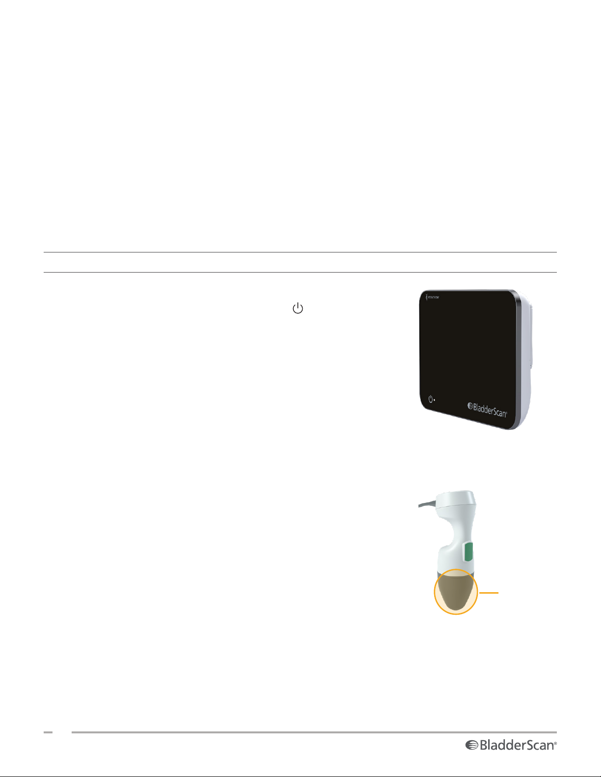
BEST PRACTICES & INSTRUCTIONS
Cleaning is the removal of all visible soil or contaminants, and disinfection is the process of destroying
pathogenic organisms or rendering them inert. When cleaning, make sure all foreign matter is removed. This
allows the active ingredients of the disinfectant to reach all surfaces.
When cleaning and disinfecting the system or its accessories, follow these best practices:
• Do not let gel or other contaminants dry on the system. This makes removal more difficult.
• Change gloves if they become visibly soiled.
• Always wipe from a clean surface towards a dirty surface.
• As you wipe, overlap your strokes as little as possible.
• If a wipe becomes dry or soiled, replace it with a fresh one.
• Do not reuse dry or soiled wipes.
PROCEDURE 1. CLEAN & DISINFECT THE CONSOLE, PROBE, & CABLE
CLEAN THE CONSOLE, PROBE, & CABLE
1. If the system is on, press the On/Offbutton . If prompted, confirm
that you want the system to shut down, and then wait for it to do so.
2. Wipe any ultrasound gel completely off of the probe.
3. Using a solution or wipe listed as a cleaner in Table 12, wipe the
console, probe, and probe cable according to the instructions
provided by the cleaner’s manufacturer. (If you are using a solution,
apply it with a clean towel.) Repeat as needed to make sure that all
visible contamination is removed.
4. If the console remains wet, you may use a clean soft cloth or
paper towel to remove any residual cleaningsolution. Allow the
touchscreen to dry completely before use.
DISINFECT THE PROBE
5. Using a germicidal wipe with an active ingredient class from Table 11,
wipe the probe dome according to the instructions provided by the
wipe’s manufacturer.
Wipe again as many times as necessary to keep the component
visibly wet for the entire exposure period. You may use as many
wipes as you need.
6. Allow the probe to air dry completely. Cleaning and disinfection is
complete, and the system is ready foruse.
Probe dome
52
0900‑5005 REV‑00
Page 61
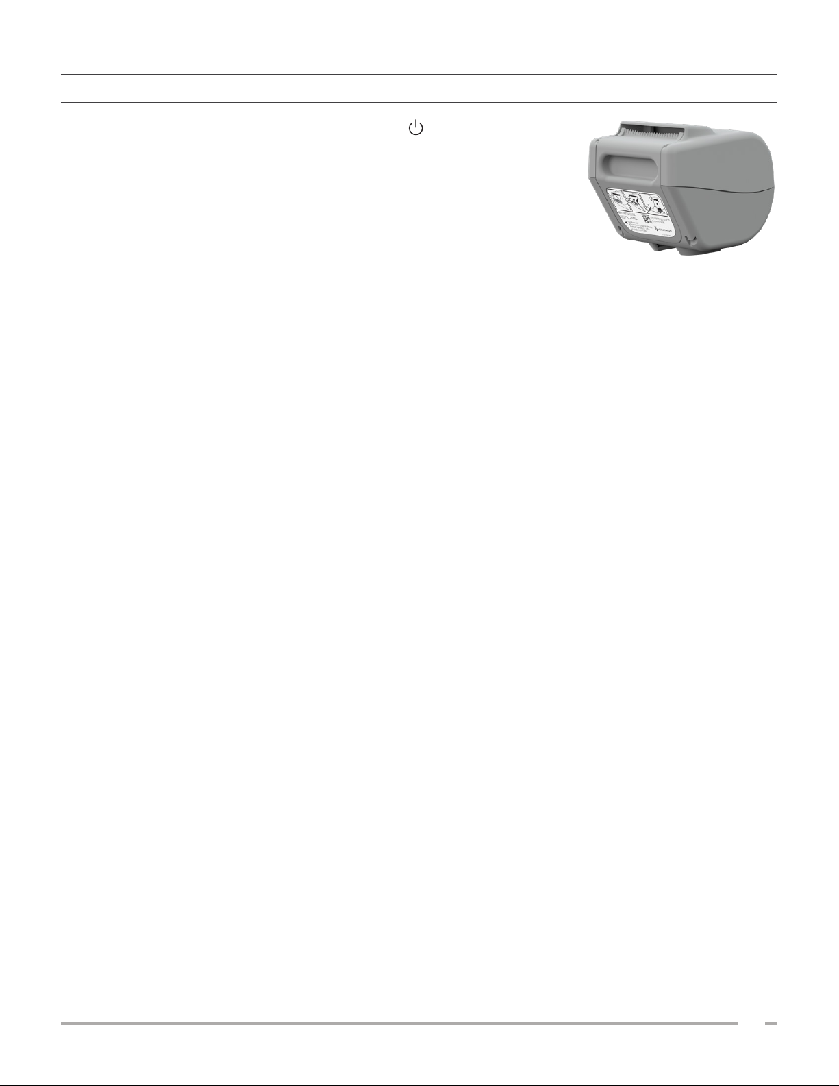
PROCEDURE 2. CLEAN THE PRINTER (OPTIONAL)
1. If the system is on, press the On/Offbutton . If prompted, confirm
that you want the system to shut down, and then wait for it to do so.
2. Using a wet cloth or a wipe indicated for cleaning medical devices,
wipe the printer according to the instructions provided by the
wipe’s manufacturer. Repeat as needed to make sure that all visible
contamination is removed.
3. If the printer remains wet, you may use a clean soft cloth or paper
towel to remove any residual cleaningsolution.
Operations & Maintenance Manual: Reprocessing
53
0900‑5005 REV‑00
Page 62

MAINTENANCE & SAFETY
REGULAR INSPECTIONS
Verathon offers certification services through authorized BladderScan service representatives or a Verathon
service center. Certification service includes comprehensive inspection and testing of the system. For more
information, contact your authorized Verathon Service Center, your local BladderScan distributor, or Verathon
CustomerCare.
WEEKLY INSPECTIONS
Once a week, you should inspect the following system components for damage or cracks:
• Console
• Probe
• Probe cable
• Printer
• Printer cable
• Workstation
• Power adapter
• Power cable
• Power cord
• Battery or batteries
• Plugs
Cracks that allow the ingress of fluid into the console or probe may affect the performance of the system.
Other than the maintenance included in this manual, all service and repairs must be completed by an
authorized BladderScan service representative or Verathon Service Center. For more information, contact
Verathon CustomerCare or your local representative.
CALIBRATION
The system does not require routine or periodic calibration under normal use.
If your facility or regional regulations require periodic maintenance, refer to the procedure “Complete a
CaliScan Test” on page59, which can be used to confirm proper probe functionality.
54
0900‑5005 REV‑00
Page 63

SYSTEM SOFTWARE
Verathon may release software upgrades for the system. Software upgrades are supplied directly by Verathon
or an authorized representative. For information about how to upgrade the device software, see “Update the
Software” on page58.
Do not perform any software upgrades from third‑party vendors or attempt to modify the existing software.
Doing so may damage the system and void the warranty.
DEVICE DISPOSAL
The system and accessories may contain mineral oils, batteries, and other environmentally hazardous
materials. When the system has reached the end of its useful service life, return it and any related accessories
to a Verathon Service Center for proper disposal. Alternatively, follow your local protocols for hazardous
waste disposal.
WARRANTY
Information about the manufacturer’s warranty is included with the product. Extended warranties
may be available for your system. For more information, contact Verathon Customer Care or your local
representative.
Operations & Maintenance Manual: Maintenance & Safety
55
0900‑5005 REV‑00
Page 64
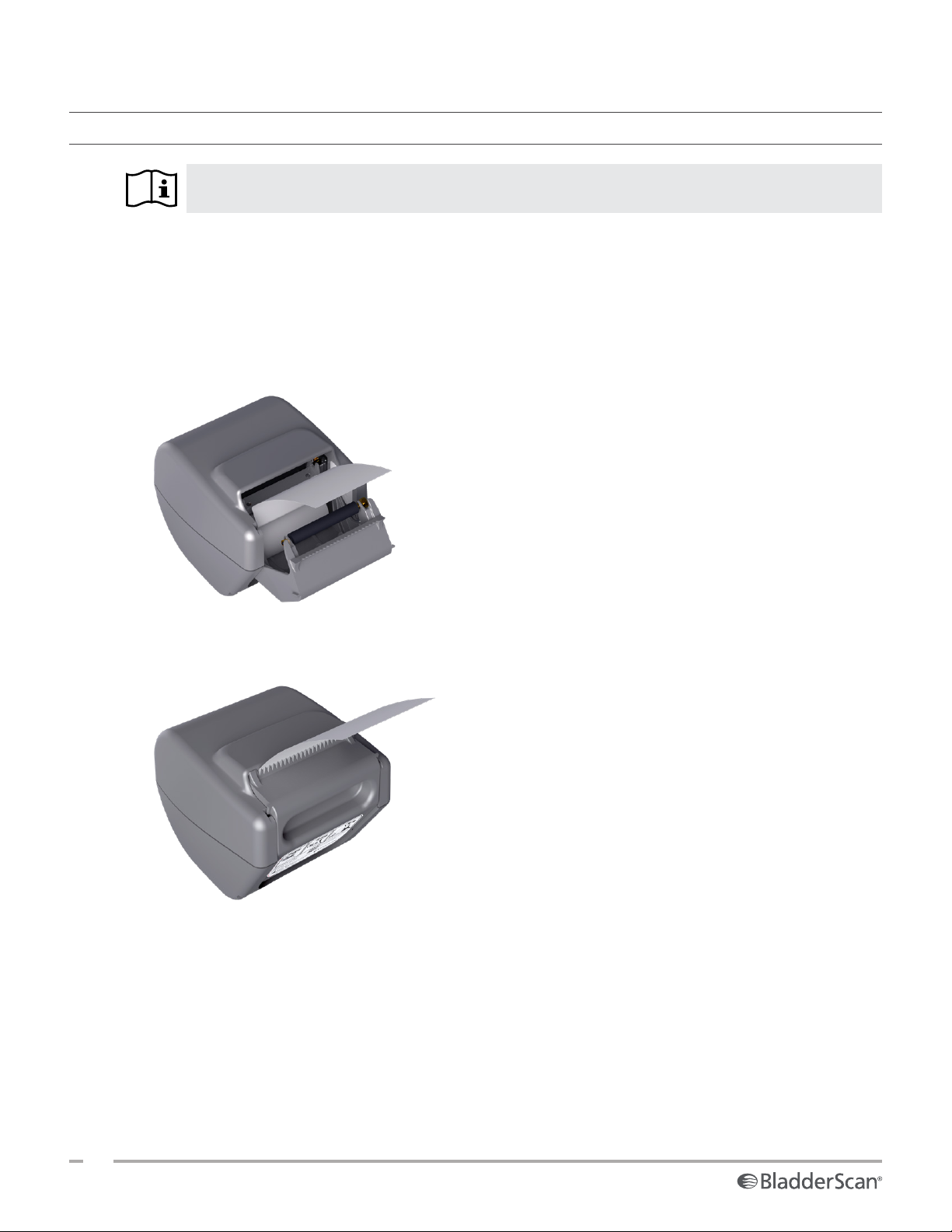
MAINTENANCE PROCEDURES
PROCEDURE 1. LOAD THERMAL PAPER INTO THE PRINTER (OPTIONAL)
Read the “Warnings & Cautions” section before performing the following task.
1. Slide the printer door upward to unlock it, and then rotate the door down to open. Placing your thumb
on the outside of the printer and squeezing can make it easier to open the door.
2. If this is the first time you are loading the printer, there may be a sheet of paper in the printer
mechanism. Remove the paper sheet.
3. Place a roll of thermal paper inside the door as shown so that the loose end of the paper exits over the
top of the roll.
4. Hold the paper end so that it protrudes from the top of the printer, and then close the printer door.
Make sure the door clicks into place.
5. Tear off any excess paper protruding from the printer. For best results, pull the paper diagonally, starting
the cut on one side of the paper and finishing on the other.
56
0900‑5005 REV‑00
Page 65
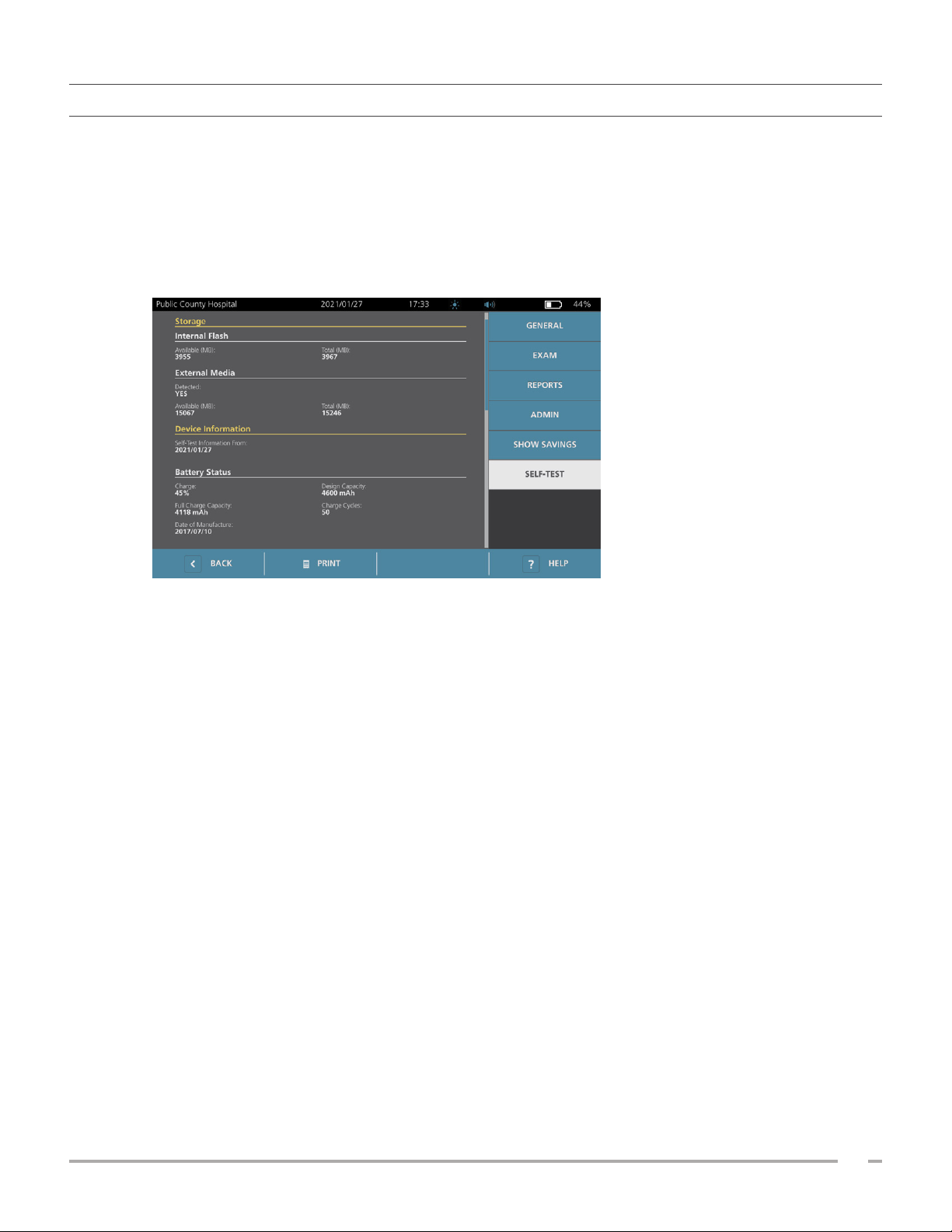
PROCEDURE 2. RUN A SELF‑TEST
The BladderScan i10 self‑test function completes self‑diagnostic testing on the following:
• Internal memory (and external devices, if any)
• Hardware components, including the console, installed battery, probe, and printer, if attached
• BladderScan i10 software
1. On the Home screen, tap the Settings icon, and then tap Self‑Tes t. The Settings screen opens to the
Self‑Testtab, where the system completes the self‑test and displays the results.
2. Scroll through the on‑screen test results by vertically swiping with your finger on the touchscreen.
3. If the screen indicates any failed tests or abnormal results, contact Verathon CustomerCare or your local
representative.
4. If you want to print the self‑test results, tap Print.
5. When you are finished viewing the test results, tap Back. The console returns to the Homescreen.
Operations & Maintenance Manual: Maintenance & Safety
57
0900‑5005 REV‑00
Page 66
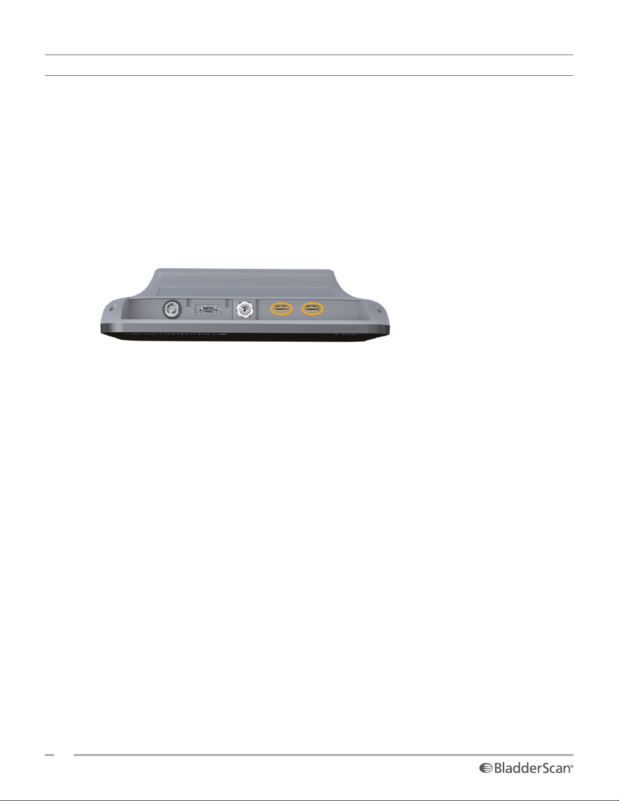
PROCEDURE 3. UPDATE THE SOFTWARE
From time to time, Verathon may make software updates available for your system. To inquire about the
availability of a software update, contact Customer Care or your local representative.
1. Export any exams you need to retain. For more information, see “Export Saved Exams” on page49.
2. Make sure the probe is attached to the console.
3. If there are any USB drives connected to the console, remove them.
4. Make sure that the system is displaying the Home screen and that its battery is at least 20% charged.
5. If the system is connected to external power, disconnect it.
6. Insert a USB drive containing a valid software update package into one of the two larger USB ports on
the console.
The system begins updating and may restart during the update process. Do not remove the battery or
the USB drive while the update is under way.
58
0900‑5005 REV‑00
Page 67
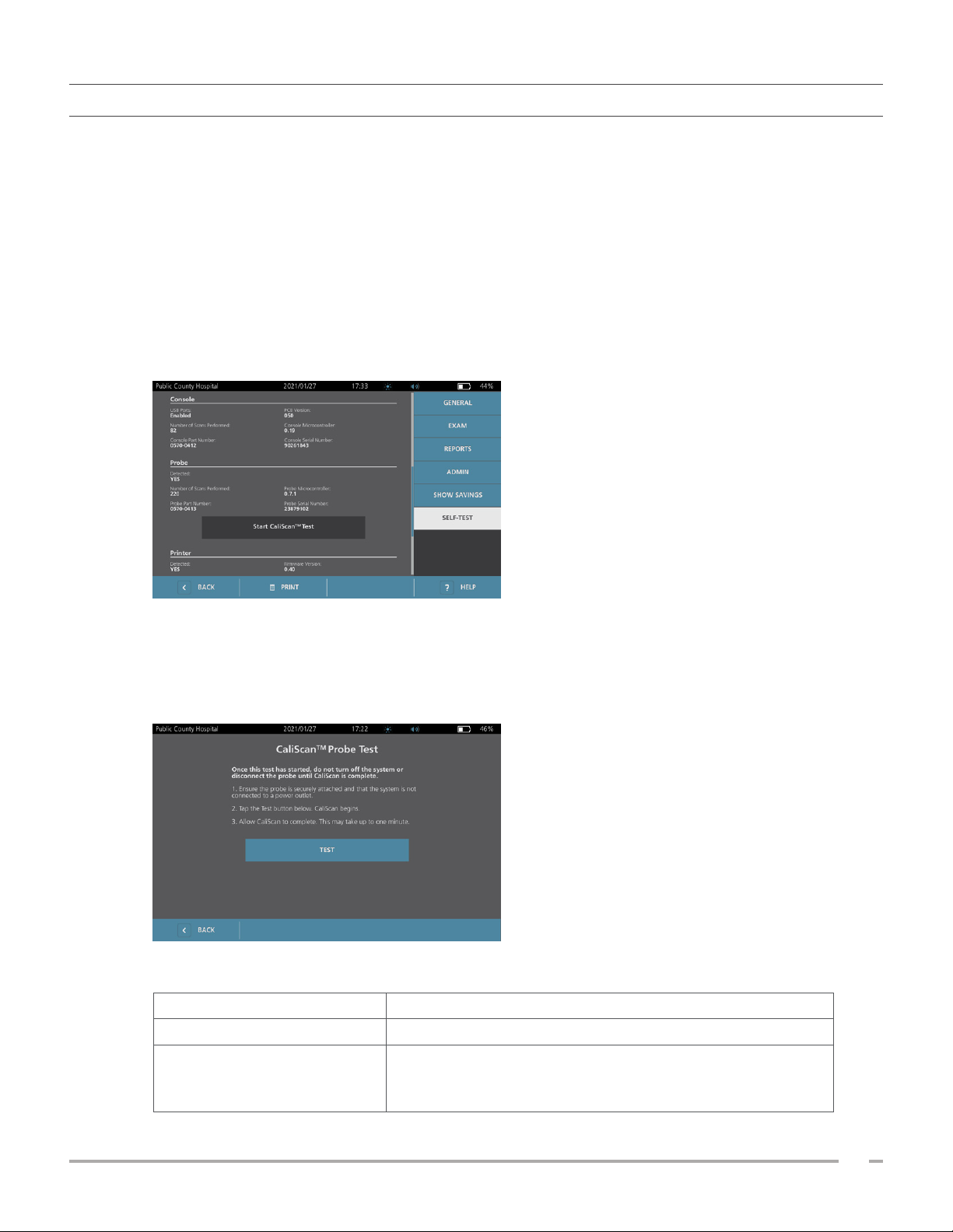
PROCEDURE 4. COMPLETE A CALISCAN TEST
The BladderScan i10 system includes the CaliScan test, which tests the probe’s mechanical components and
transducer function. This test can be used for preventative maintenance or as a diagnostic tool if a probe has
been dropped or in storage for an extended amount of time.
Note: The CaliScan test evaluates only the mechanical condition of the probe. The BladderScan i10 system
does not require calibration as normal scheduled maintenance.
1. Make sure that the BladderScan i10 system is disconnected from external power.
2. On the Home screen, tap Settings, and then tap Self‑Test.
3. Swipe upward in the list of test results until the Probe section appears.
4. Tap Start CaliScan™ Test.
5. Review the test instructions, and then tap Test. The system begins to test probe components. A message
and process indicator appear while the test is in process.
Note: Once the test has started, do not press the On/Off button or disconnect the probe from the
console.
6. Proceed according to the message that appears on the screen.
If the message reports that … Then …
The probe passed the test When you are done reviewing the results, tap Back.
Restart the system and try the test again. If the test continues
The probe failed the test
to fail, contact Verathon CustomerCare or your local
representative.
Operations & Maintenance Manual: Maintenance & Safety
59
0900‑5005 REV‑00
Page 68

PROCEDURE 5. TURN THE SYSTEM OFF
1. If you are performing an exam, save the exam information.
Note: If you omit this step and attempt to turn off the system during an exam, the system prompts you
to confirm that you want to continue without saving the exam results.
2. Press the On/Off button and hold it for about half a second.
3. When a dialog box appears on the screen and asks if you want to turn off the system, release the
On/Off button .
4. Tap Yes to confirm that you want to turn off the system.
60
0900‑5005 REV‑00
Page 69
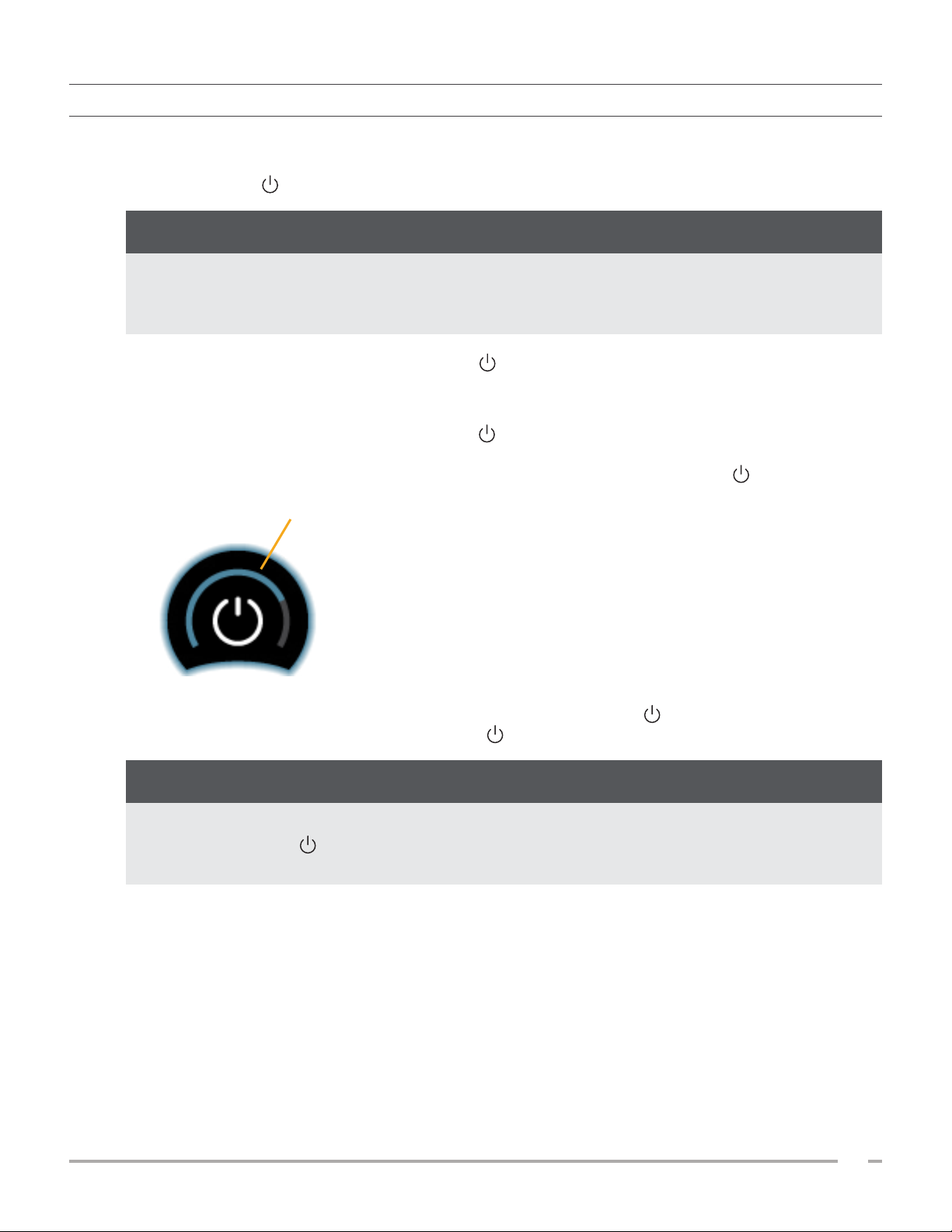
PROCEDURE 6. PERFORM AN UNCONDITIONAL SHUTDOWN
If it becomes necessary for emergency or troubleshooting reasons, you can shut down the system
unconditionally. The system stops all running processes and shuts down immediately. The next time you press
the On/Off button , there will be a wait of several seconds before the Home screen appears.
IMPORTANT
If the system is displaying the results of an unsaved exam, save the exam before you continue. You can
turn off the system completely while you are evaluating an unsaved exam, but if you do so, the exam
information is lost.
1. Place a finger or thumb on the On/Off button and hold it in place for at least 1.5 seconds. A
shutdown indicator appears at the lower left corner of the screen. A progress bar within the indicator
becomes progressively shorter while the system waits to begin its shutdown routine.
Note: When you first press the On/Off button , the option to turn the system off normally is still
available, and the system displays the dialog box asking if you want to turn it off that way. While the
shutdown indicator is on the screen, removing your finger from the On/Off button cancels the
shutdown.
Progress bar
2. Continue holding your finger or thumb in place on the On/Off button until the console’s touchscreen
is black and the LED next to the On/Off button is no longer illuminated.
IMPORTANT
If the system becomes completely unresponsive, you can still shut it down by placing a finger or thumb
on the On/Off button and holding it in place for 6 seconds or longer. If you shut the system down
this way, however, some stored information may be lost.
Operations & Maintenance Manual: Maintenance & Safety
61
0900‑5005 REV‑00
Page 70

PROCEDURE 7. COPY THE SYSTEM’S CONFIGURATION TO OTHER SYSTEMS
After you have set up a BladderScan i10 system with the configuration you want to use throughout your
facility, you can copy the configuration from the first system to all of the others.
Note: The following two procedures copy all settings except for the asset tag on the original system.
EXPORT A SYSTEM’S CONFIGURATION TO A USB FLASH DRIVE
1. Insert a blank USB flash drive into an open USB port on the console.
2. At the Home screen, tap Settings.
3. At the Settings screen, tap the Admin tab.
4. If a keypad appears, key in the PIN for Settings, and then tap Enter.
5. On the Admin tab, tap Export Settings to USB.
6. When you are asked if you want to export the settings, tap Yes.
7. When the progress indicator disappears, disconnect the USB flash drive from the console.
8. Tap the Back button twice. This returns you to the Home screen.
IMPORT A CONFIGURATION TO ANOTHER SYSTEM
When the system detects that a USB flash drive has been connected, it scans the drive for a configuration
file. If it finds one, it automatically proceeds to import the configuration. As a result, you can apply an
exported configuration to a different system by simply connecting the USB flash drive that contains the
configuration. If the system is on, the import process begins automatically; if not, the process begins when
you turn on the system.
Do not begin importing a configuration if any of the following is true:
• The system is performing a scan, or an exam has not been saved.
• The system is busy.
• Another USB flash drive is already connected.
• The system’s battery is less than 20% charged.
When the import is complete, the system restarts with the imported settings in place. To prevent the system
from importing the configuration again, remove the USB flash drive at this point.
62
0900‑5005 REV‑00
Page 71
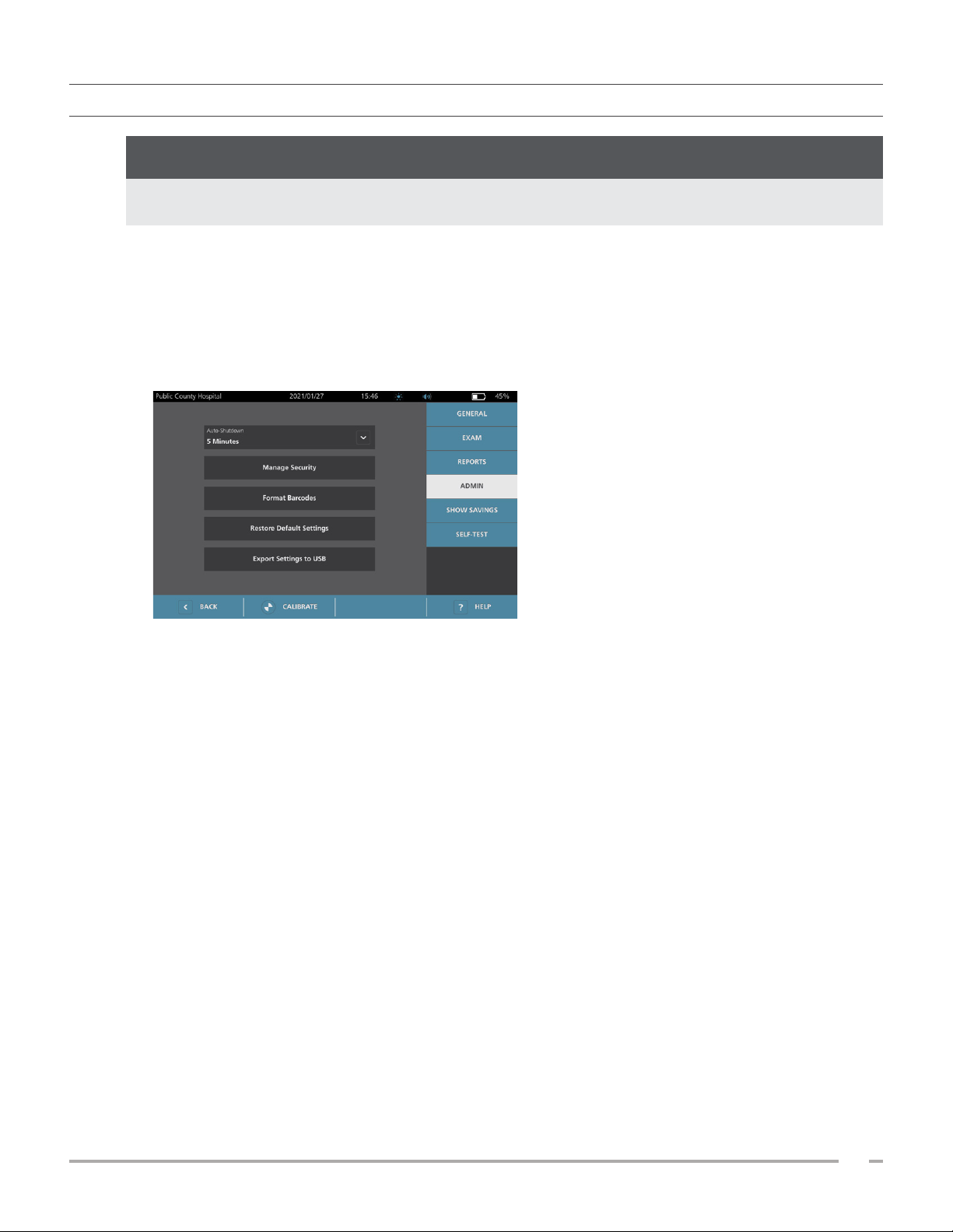
PROCEDURE 8. TURN OFF THE USB PORTS
IMPORTANT
If a printer is connected, it cannot operate unless the USB ports are active.
Under normal circumstances, the three USB ports on the console are active and available for use. However, if
necessary, you can deactivate them by following this procedure.
1. At the Home screen, tap Settings.
2. At the Settings screen, tap the Admin tab.
3. If a keypad appears, key in the PIN for Settings, and then tap Enter.
4. On the Admin tab, tap Manage Security.
5. In the Manage Security dialog box, tap the Enable USB Ports check box to clear it.
6. Tap the Back button twice. This returns you to the Home screen.
Operations & Maintenance Manual: Maintenance & Safety
63
0900‑5005 REV‑00
Page 72
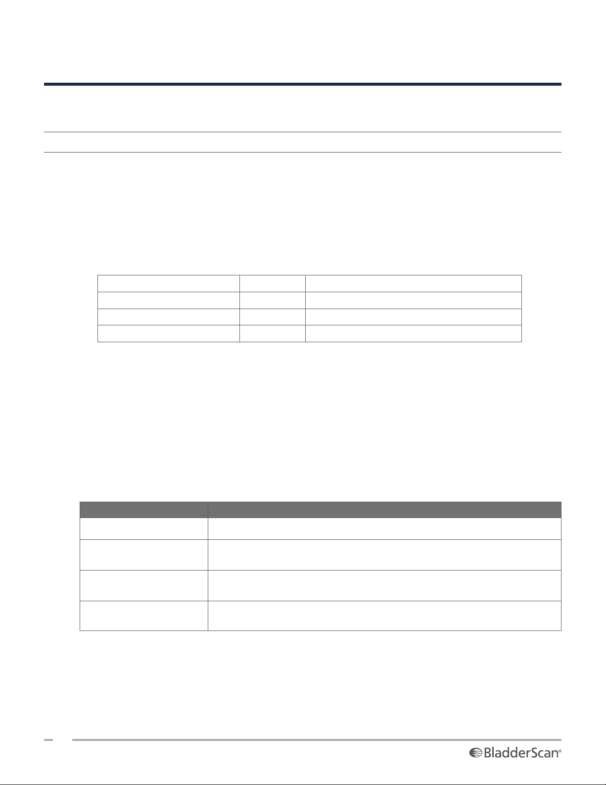
HELP & TROUBLESHOOTING
HELP RESOURCES
PROCEDURE 1. WATCH THE ONBOARD TUTORIAL
The BladderScan i10 system includes an onboard tutorial with instructions on how to scan and manage
exams. It is recommended that you watch the tutorial before using the system. The tutorial does not include
an audio track.
Note: The setting and configuration screens include access to screen‑specific help text. To see help text on
any setting or configuration screen, tap Help.
1. Tap the appropriate button on the screen that is currently displayed. The Tutorial Control screen opens
and the tutorial begins to play.
On… Tap… The tutorial starts at…
The Home screen Tutorial The beginning
The Results screen Help The section on viewing and saving results
The Saved Exams screen Help The section on reviewing saved exams
While the tutorial is playing, you can take these actions:
• View the previous frame of the tutorial (tap Previous)
• View the next frame of the tutorial (tap Next)
• Pause the tutorial (tap Pause) or continue the tutorial when paused (tap Play)
• When you are done viewing the tutorial, tap Exit.
CUSTOMER SERVICES RESOURCES
Verathon provides several customer service resources, as described in Table 13.
Table 13. Customer Service Resources for BladderScan i10 Systems
RESOURCE DESCRIPTION
In‑serviceUSB USB drive included with your system that includes instructions on using it.
Onboard help tutorial
Onboard help text
Phone support
A training module installed on your BladderScan is available by pressing Help
from the Home, Aiming, and Results screens.
Screen‑specific online help text is available by pressing Help from the setting
and configuration screens.
Refer to the list of Verathon CustomerCare resources available at
verathon.com/global‑support
64
0900‑5005 REV‑00
Page 73
DEVICE REPAIR
The system components are not user‑serviceable. Verathon does not make available any circuit diagrams,
component parts lists, descriptions, or other information that would be required for repairing the device
and related accessories. All service must be performed by a qualified technician. If you have any questions,
contact Verathon CustomerCare or your local representative.
Read the “Warnings & Cautions” section.
TROUBLESHOOTING PROCEDURES
PROCEDURE 1. TROUBLESHOOT CONSOLE BATTERY ISSUES
1. If the system does not turn on, the battery may be dead or simply discharged. To determine the battery’s
condition, attempt to recharge it according to the instructions in the procedure “Charge the Battery” on
page25.
2. If you cannot recharge the battery but a second battery is available, remove the first battery and insert
the second battery. If necessary, charge the second battery according to the instructions in the procedure
“Charge the Battery” on page25, and then verify that the system operates normally.
3. If the system does not respond to these troubleshooting steps, contact Verathon CustomerCare.
Operations & Maintenance Manual: Help & Troubleshooting
65
0900‑5005 REV‑00
Page 74
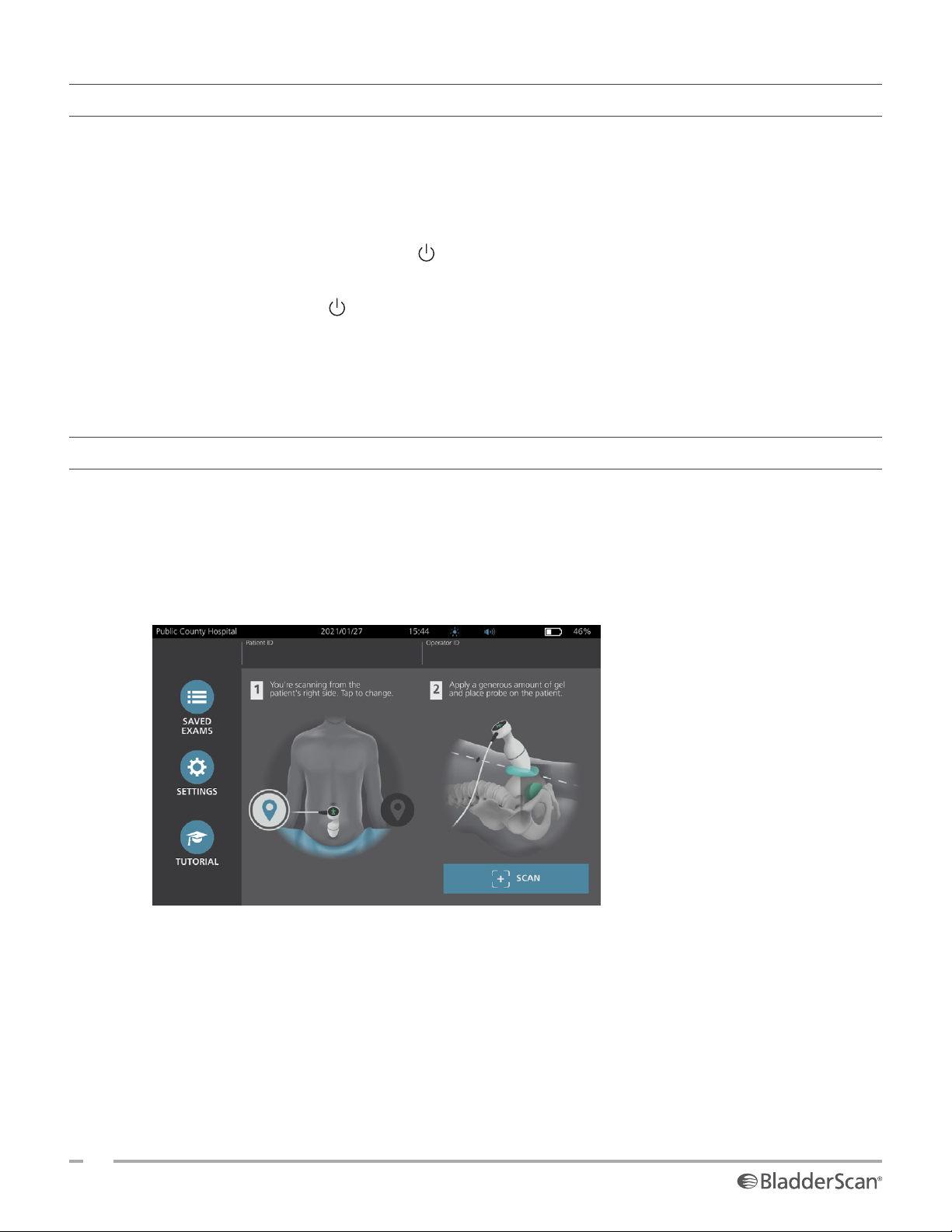
PROCEDURE 2. TROUBLESHOOT PROBE CONNECTION ISSUES
If the probe is not functioning, or if the console displays an error message indicating that the probe is not
attached, use this procedure to troubleshoot the issue.
1. Check to see if external power is connected. If it is, disconnect it. If this does not resolve the problem,
continue to Step 2.
2. If necessary, press the On/Off button . When prompted, confirm that you want the system to turn off,
and then wait for it to do so.
3. Press the On/Off button again to activate the system.
4. If the message appears again and you have an extra battery, repeat Step 2. Replace the battery according
to the instructions in the procedure “Insert a Battery” on page23, and then repeat Step 3.
5. If the message still appears, contact Verathon CustomerCare.
PROCEDURE 3. TROUBLESHOOT PROBE AIMING ISSUES
Use this procedure to troubleshoot the following problems:
• The initial aiming scan is not successful.
• The aiming image is off center, but moving the probe in the expected direction of the bladder moves
the image further off center.
1. On the Home screen, verify that the selected position reflects your position in relation to the patient.
66
0900‑5005 REV‑00
Page 75
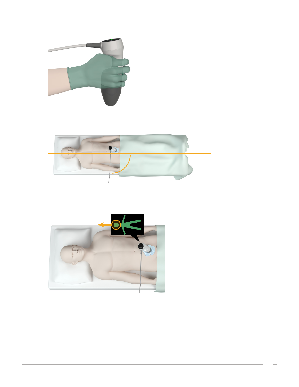
2. Hold the probe by grasping it with the probe cable running up your wrist and forearm.
3. With the probe midline on the patient, make sure the probe cable is oriented at 90 degrees to the
sagittal plane.
Sagittal plane
90°
Probe cable
4. Look at the position indicator icons on the top of the probe. Make sure the head of the lighted direction
indicator points in the same direction as the head of the patient.
5. After verifying the selected orientation, probe placement, and probe display, rescan the patient. Hold
the probe steady while the scan is in process. For detailed scanning instructions, see “Measure Bladder
Volume” on page39.
Operations & Maintenance Manual: Help & Troubleshooting
67
0900‑5005 REV‑00
Page 76

PROCEDURE 4. RESTORE FACTORY DEFAULTS
Use this procedure to restore the original settings for the system. Running this procedure removes all user
information—including customized system settings, cost savings calculations, and saved exams—from the
system. Do not restore factory defaults if you want to retain this information.
1. On the Home screen, tap Settings, and then tap Admin.
2. If a keypad appears, key in the PIN for Settings, and then tap Enter.
3. Tap Restore Default Settings.
4. If you want to restore the system defaults, tap Yes. The system restores factory settings and then
restarts.
68
0900‑5005 REV‑00
Page 77
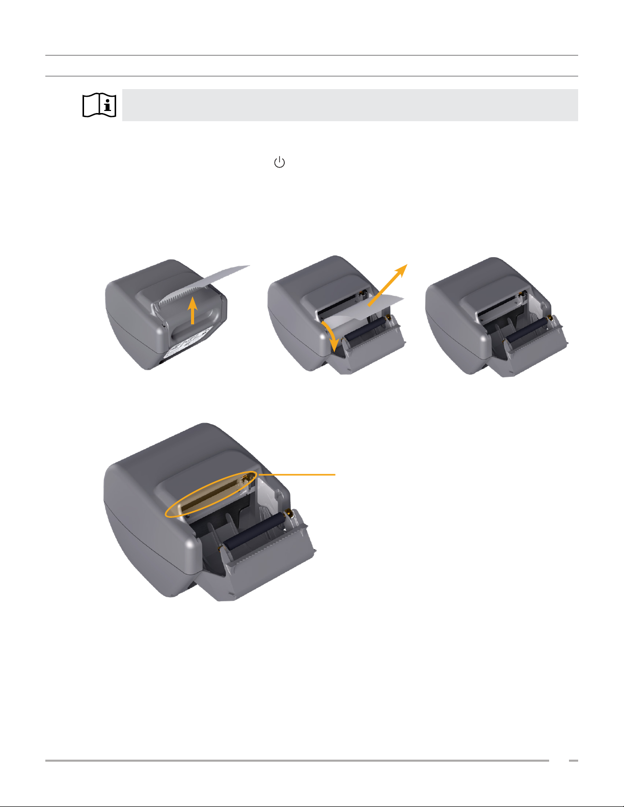
PROCEDURE 5. TROUBLESHOOT IRREGULAR PRINTOUTS (OPTIONAL)
Read the “Warnings & Cautions” section before performing the following task.
If the printer is producing irregular printouts, you may need to clean the print head.
1. If necessary, press the On/Off button . When prompted, confirm that you want the system to turn off,
and then wait for it to do so.
2. Slide the printer door upward to unlock it, and then rotate the door down to open. Placing your thumb
on the outside of the printer and squeezing can make it easier to open the door.
3. If a thermal paper roll is in the printer, remove it.
4. Using a cotton swab dipped in isopropyl alcohol (IPA), wipe along the length of the print head. Do not
use your fingers or any hard or abrasive surfaces to clean the print head.
Print head
5. Allow the print head to dry completely.
6. Make sure there is no lint or visible debris on the print head.
Operations & Maintenance Manual: Help & Troubleshooting
69
0900‑5005 REV‑00
Page 78
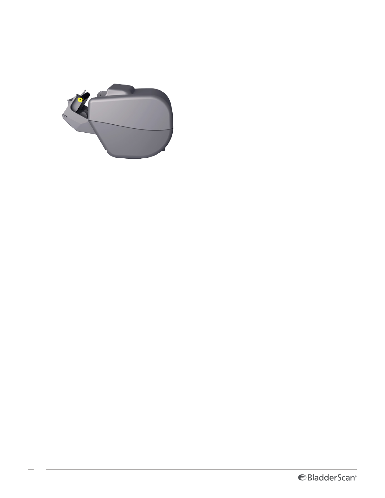
7. Verify the position of the printer driver roller in the printer door:
• The printer drive roller’s plastic bushings should rest inside the light gray plastic clips in the printer
door as shown. The gear should be outside the clip.
• If the printer drive roller has fallen out of the gray clips, replace it according to the instructions in the
procedure “Replace the Printer Drive Roller (Optional)” on page72.
8. Load the thermal paper and close the printer door according to the instructions in the procedure “Load
Thermal Paper into the Printer (Optional)” on page56.
9. If the printer continues to produce irregular printouts, contact Verathon CustomerCare.
70
0900‑5005 REV‑00
Page 79
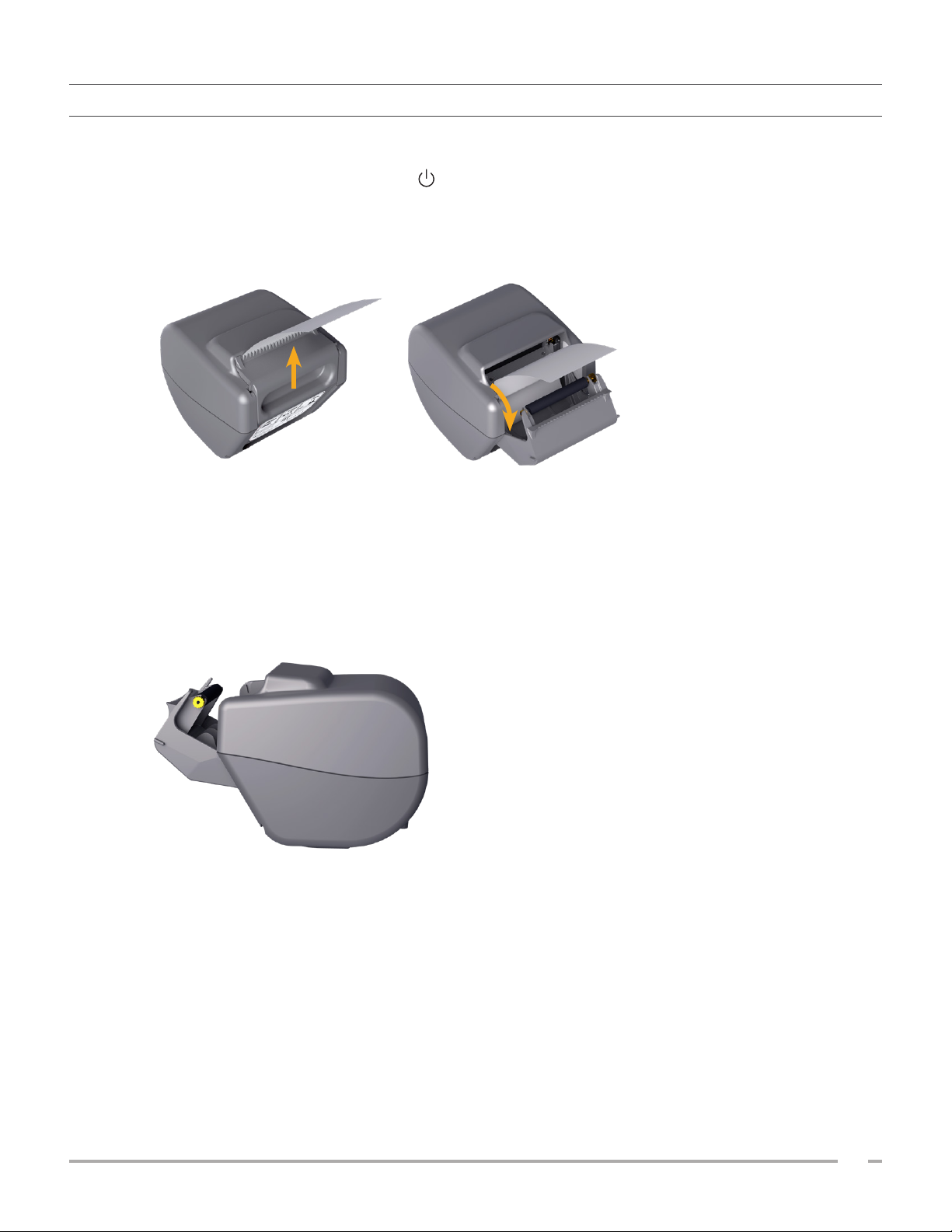
PROCEDURE 6. CLEAR A PAPER JAM (OPTIONAL)
If the printer is jammed, follow this procedure to remove the paper jam.
1. If necessary, press the On/Off button . When prompted, confirm that you want the system to turn off,
and then wait for it to do so.
2. Slide the printer door upward to unlock it, and then rotate the door down to open. Placing your thumb
on the outside of the printer and squeezing can make it easier to open the door.
3. Pull the paper gently to clear the paper jam. If necessary, pull any ripped or folded paper out of the
printer and remove any bits of paper that have become separated from the roll.
4. Verify the position of the printer drive roller in the printer door:
• The printer drive roller’s plastic bushings should rest inside the light gray plastic clips in the printer
door as shown. The gear should be outside the clip.
• If the printer drive roller has fallen out of the gray clips, replace it according to the instructions in the
procedure “Replace the Printer Drive Roller (Optional)” on page72.
5. Load the thermal paper and close the printer door according to the instructions in the procedure “Load
Thermal Paper into the Printer (Optional)” on page56.
6. If the paper on the outside of the printer is ripped or torn, tear it off, pulling to one side to aid in cutting.
7. If you cannot clear the paper jam or the printer continues to jam, contact Verathon CustomerCare.
Operations & Maintenance Manual: Help & Troubleshooting
71
0900‑5005 REV‑00
Page 80
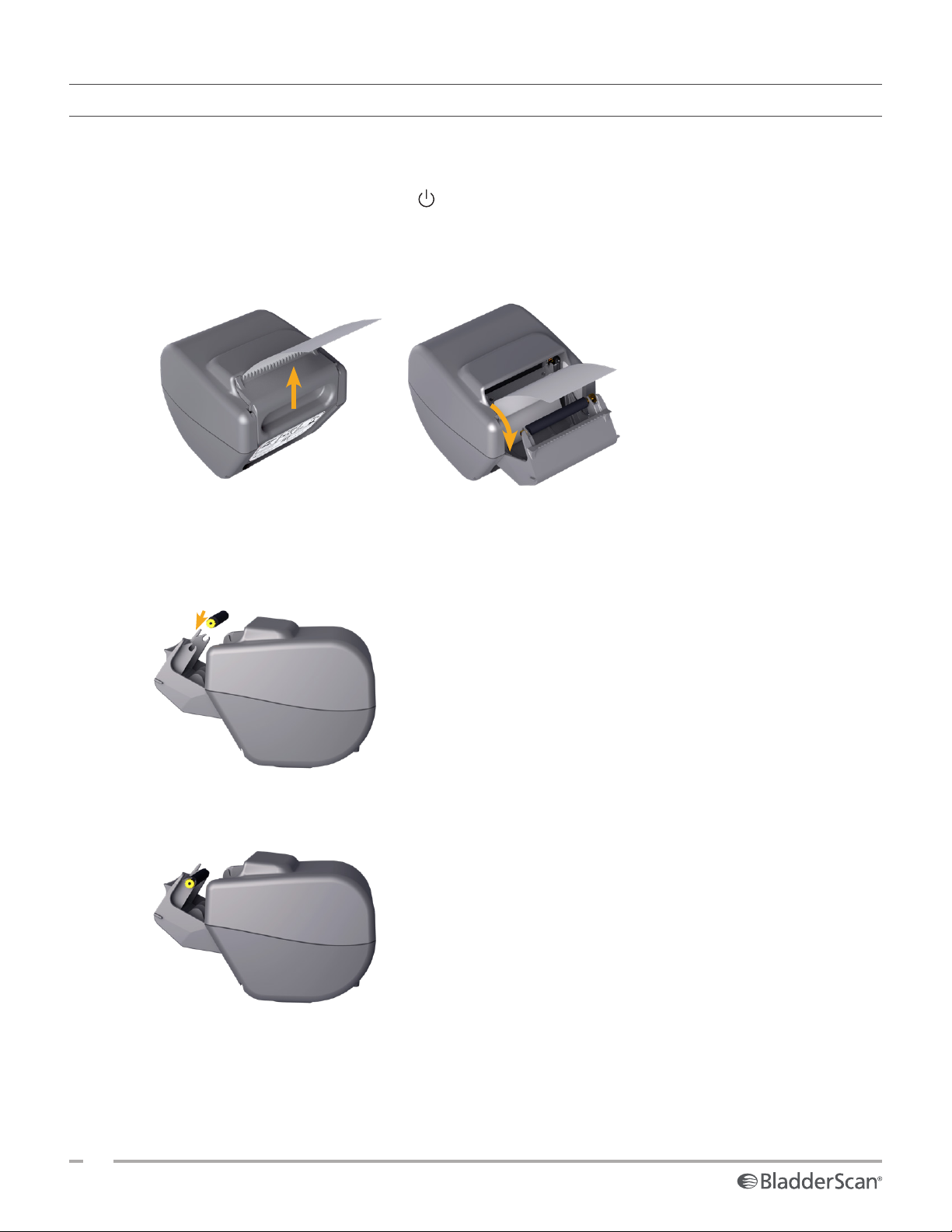
PROCEDURE 7. REPLACE THE PRINTER DRIVE ROLLER (OPTIONAL)
The printer drive roller can fall out if the printer is dropped. If the roller has fallen out, printing may be
irregular or not occur at all. You may be unable to close the printer door.
1. If necessary, press the On/Off button . When prompted, confirm that you want the system to turn off,
and then wait for it to do so.
2. Slide the printer door upward to unlock it, rotate the door down to open, and then remove the paper
roll.
3. Look for the printer drive roller inside the light gray plastic clips in the printer door.
4. If the printer drive roller has fallen out, put it back into place as shown. The gear should be on the right
when viewed from the front of the printer, and the plastic bushings should be centered between the
light gray clips in the printer door.
5. Push down on the printer drive roller to seat it. Make sure that it snaps into the light gray clips in the
printer door and is held in place on both sides.
6. Load the thermal paper and close the printer door according to the instructions in the procedure “Load
Thermal Paper into the Printer (Optional)” on page56.
7. If the printer continues to malfunction, contact Verathon CustomerCare.
72
0900‑5005 REV‑00
Page 81

PROCEDURE 8. EVALUATE CONSOLE ERROR MESSAGES
Table 14 lists the initial actions you should take if one of the error messages in the table appears on the
system’s main display. If you are not able to correct the error, contact Verathon Customer Care for additional
instructions.
Table 14. Common Console Error Messages
MESSAGE TEXT TROUBLESHOOTING STEPS
The console is too hot. Turn off
the system and allow the battery
to cool.
Turn off the system, disconnect external power, and wait for the
battery to return to a normal temperature.
The console is too hot and may
turn off if the temperature
increases.
Overcharged battery. Turn off the
system and contact Verathon.
Incompatible software versions.
Contact Verathon.
Please unplug the system from the
power outlet to begin scanning.
Please unplug the system from the
power outlet to resume scanning.
No probe detected. Please connect
a probe to begin scanning.
No probe detected. Please connect
a probe to resume scanning.
Loss of ultrasound data.
Data stream error. The scan is
missing some ultrasound data.
Probe motor error. The scan
may not completely measure the
bla dder.
Transducer error. The probe may
not capture ultrasound data.
The scan did not identify a
bla dder.
External storage device removed.
Internal storage will be used.
Insufficient storage space. Please
delete exams or insert storage
device.
Turn off the system and wait until the battery returns to a normal
temperature.
Turn off the system and contact Verathon Customer Care.
Make sure you are using the system with its original probe.
Disconnect external power from the system before you start
scanning. The probe does not function while external power is
connected.
Disconnect external power from the system until you have saved and
completed the exam. The probe does not function while external
power is connected.
Check the connection between the probe and the console to make
sure it is secure.
Contact Verathon Customer Care.
Make sure the probe is securely in contact with the patient, that you
are using enough gel, and that the probe is positioned correctly.
Check the connection between the USB flash drive and the console.
Alternatively, use a different USB flash drive.
Transfer older files from the USB flash drive to a computer, and then
delete those files from the USB flash drive, before you connect the
drive to the console.
Alternatively, use a different USB flash drive.
Operations & Maintenance Manual: Help & Troubleshooting
73
0900‑5005 REV‑00
Page 82
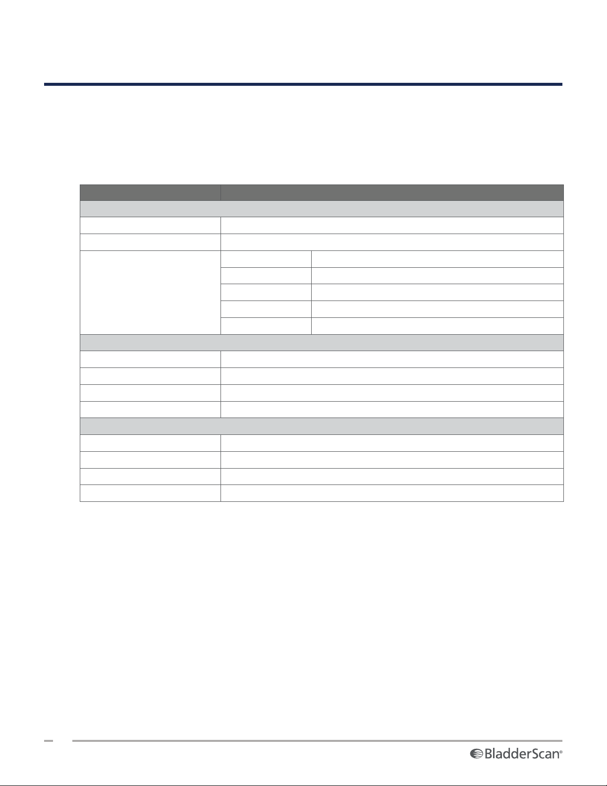
PRODUCT SPECIFICATIONS
SYSTEM SPECIFICATIONS
OVERALL SYSTEM SPECIFICATIONS
Table 15. General System Specifications
ITEM SPECIFICATION
General Specifications
Classification Internally powered, Type BF
Expected product life 7 years
Console IPX2
Probe IPX4
Ingress protection (IP) against
water
Use Indoor
Temperature +10 to +40°C (50 to 104°F)
Relative humidity 20 to 75%
Ambient air pressure +700 hPa to 1060 hPa
Use Indoor
Temperature ‑10 to +60°C (14 to 140°F)
Relative humidity 15 to 85%
Ambient air pressure +600 hPa to 1060 hPa
Printer IPX0
Power adapter IP22
Battery IPX0
Operating Conditions
Storage Conditions
74
0900‑5005 REV‑00
Page 83

Table 16. Ultrasound Acoustic Output Parameters (IEC Standard)
TIS TIB TIC
INDEX L ABEL MI
Maximum index value
*
0.433 2.21×10
Index component value 2.21×10
p
at z
r,α
MI
(MPa) 0.652
P (mW) 0.854 — — —
Acoustic
Parameters
P
1×1
z
s
z
b
z
MI
Z
pii,α
f
awf
(mW) 0.205 — —
(cm) 3.3
(cm) —
(cm) 3.3
(cm) 3.3
(MHz) 2.27 2.27 — — —
prr (Hz) 408
srr (Hz) 5.1
Other
Information
n
pps
I
at z
pa,α
I
spta,α
or z
sii,α
I
at z
spta
z
sii
pr at Z
at z
pii
pii
pii,α
pii,α
or
(W/cm2) 11. 3
(mW/cm2) 0.16 5
(mW/cm2) 0.277
(MPa) 0.844
1
AT SUR FACE
‑3
BELOW
SURFACE
‑3
2. 21×10
‑3
AT SUR FACE
BELOW
SURFACE
— — —
— —
Operating
Control
2.6 MHz pulse
Conditions
* MI and TI values are both below 1.0.
Operations & Maintenance Manual: Product Specifications
75
0900‑5005 REV‑00
Page 84
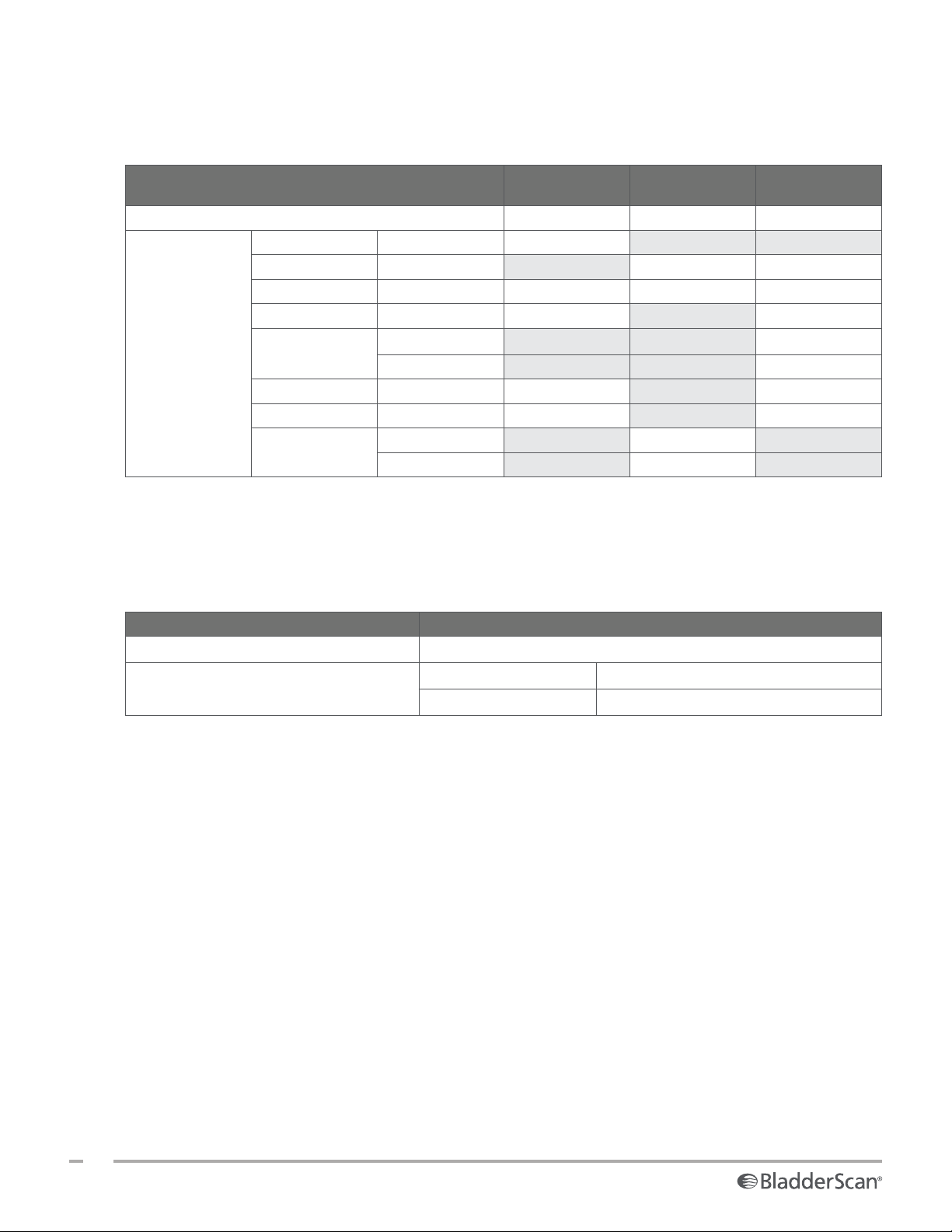
Table 17. Ultrasound Acoustic Output Parameters (FDA Format)
The data in each column corresponds to the highest measured global maximum value for each of the
parameters in the column title (MI, I
ACOUSTIC OUTPUT MI
Global Maximum Value
p
r.3
P
0
f
c
z
sp
Associated
Acoustic
Beam dimensions
Parameter
PD (µsec) 0.753 0.753
PRF (Hz) 408 408
EDS
* MI and TI values are both below 1.0.
spta.3
, I
), measured for three probes.
sppa.3
I
SPTA.3
(mW/cm2)
*
(MPa) 0.682
(mW) 0.863 0.863
(MHz) 2.29 2.29 2.29
(cm) 3.40 3.40
x
(cm)
‑6
y‑6 (cm) 0.401
Az. (cm) 5.25
Ele. (cm) 1.28
0.455 0.181 12.2
I
SPPA .3
(W/cm2)
0.401
ACCURACY SPECIFICATIONS
Table 18 . Accuracy Specifications
SPECIFICATION DESCRIPTION
Bladder volume range 0 to 999 mL
Volume accuracy
The following examples show how the accuracy ranges shown in Table 18 may affect reported volume
measurements.
• If the measurement is greater than 100mL, the accuracy range is ±7.5% and is calculated asfollows:
240mL×7.5% =18mL
240 ±18mL = 222–258mL
• If the measurement is 0–100mL, the accuracy range is ±7.5mL and is calculated as follows:
80 mL ±7.5mL = 73–88mL (rounded to the nearest whole number)
The accuracy specifications assume the system is being used according to the instructions provided by
Verathon while scanning a tissue‑equivalent phantom.
While the upper threshold of the accuracy range is 999 mL, the system is capable of detecting and displaying
bladder volumes above 999 mL. Verathon cannot guarantee the accuracy of measurements outside of the
stated specifications.
greater than 100mL ±7.5%
0–100mL ±7.5mL
76
0900‑5005 REV‑00
Page 85

COMPONENT SPECIFICATIONS
Table 19. BladderScan i10 Console (0570‑0412)
ITEM SPECIFICATION
General Specifications
Height 206 mm (8.10in)
Width 269 mm (10.59in)
Depth 69 mm (2.70in)
Weight 1800 g (3.97 lbs)
Display 1280 x 800 pixels
Electrical Specifications
Input Verathon Supplied Battery, 10.8 V DC
Output USB Ports, 5 V DC at 100 mA maximum from each port
Insulation Type BF
Table 20. BladderScan i10 Power Adapter (0400‑0156)
SPECIFICATION DESCRIPTION
Electrical Specifications
Input voltage 100–240 V AC, single phase
Input frequency 50–60 Hz
Input current 1.5A max
Input connection
Output 9–48 V DC / 0–5.41A / 65 W max
Approvals IEC 60601‑1
IEC C13 connection, line cord plug NEMA 5‑15 (North America), AS 3112 (Australia),
CEE 7/4 (Europe), BS 1363 (United Kingdom)
Operations & Maintenance Manual: Product Specifications
77
0900‑5005 REV‑00
Page 86
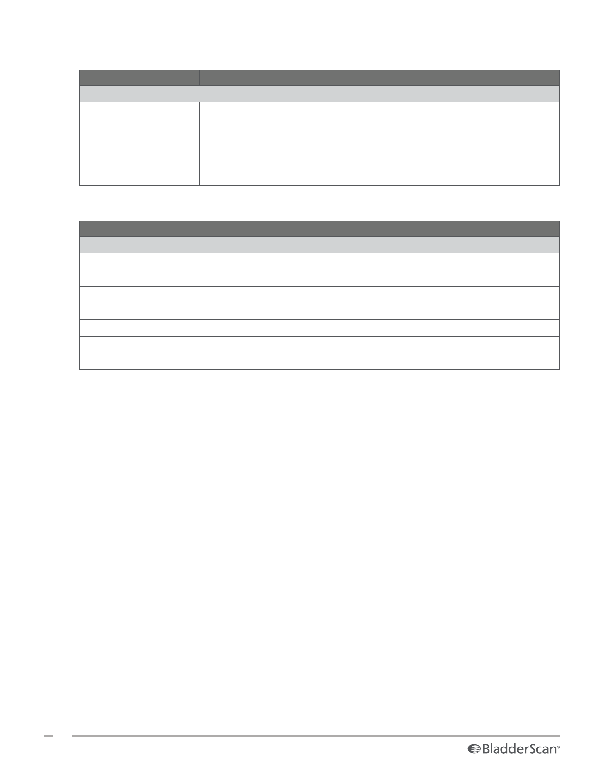
Table 21. BladderScan i10 Probe (0570‑0413)
ITEM SPECIFICATION
General Specifications
Height 194 mm (7.64in)
Width 61 mm (2.40in)
Depth 89 mm (3.50in)
Weight 470 g (1.04 lbs)
Cable 1.88m (6.17 ft)
Table 22. BladderScan i10 Printer (0800‑0640)
SPECIFICATION DESCRIPTION
General Specifications
Height 106 mm (4.17 in)
Width 103 mm (4.06 in)
Depth 122 mm (4.80 in)
Weight (without paper) 460 g (1.01 lbs)
Resolution 8 dots/mm (203 dots/in)
Dot size 0.125 mm by 0.12 mm (0.005 in by 0.005 in)
Printing width 48 mm (1.89 in), or 384 dots/line
78
0900‑5005 REV‑00
Page 87

BATTERY SPECIFICATIONS
The system includes a lithium‑ion battery. A battery symbol on the touchscreen display is always present,
indicating how much power remains and when the battery needs to be recharged or changed. If you have
purchased additional batteries and the optional battery charger, you can change the battery whenever
necessary.
Adhere to the following recommendations and guidance:
• Use only the console itself or the optional Verathon battery charger. Any other battery charger may
damage the batteries.
• Use only the battery model described in this section.
• Consider replacement of the battery if the time between battery charges is significantly reduced and
is affecting your use of the BladderScan i10 system. Contact Verathon Customer Care or your local
representative to order replacement batteries.
Table 23. Battery (0400‑0155)
CONDITION DESCRIPTION
Battery type Lithium Ion (Li‑Ion)
Height 23mm (0.89in)
Width 151mm (5.94in)
Depth 59mm (2.32in)
Weight 326g (0.72 lbs)
Battery life
Charging time 2.5 hours (typical)
Rated capacity 6.4 Ah, 70 Wh
Nominal voltage 10.8 V
Max charging voltage 12.6 V
General Specifications
Electrical Specifications
A fully charged battery will typically provide more than 24hours of normal
operating use between charges
Operations & Maintenance Manual: Product Specifications
79
0900‑5005 REV‑00
Page 88
BATTERY CHARGER SPECIFICATIONS
Note: The battery charger is an optional accessory.
Table 24. Battery Charger (0400‑0157)
SPECIFICATION DESCRIPTION
General Specifications
Height 58 mm (2.30in)
Width 124 mm (4.89in)
Depth 175 mm (6.89in)
Weight 385 g (0.85 lbs)
Electrical Specifications
Input voltage 24 V DC
Input frequency DC
Input current 2.5 A
Input connection 2.5 mm (0.1 in), center positive
Output 18 V DC max, 4 A max
Insulation Protection Class III
Fuses No user replaceable fuses
Table 25. Battery Charger Power Adapter
SPECIFICATION DESCRIPTION
Electrical Specifications
Input voltage 100–240 V AC, single phase
Input frequency 50–60 Hz
Input current 1.4A max
Input connection
Output 24 V DC / 0–2.71A
Insulation 10 Megaohm for 500V DC
Fuses
IEC C13 connection, line cord plug NEMA 5‑15 (North America), AS 3112 (Australia),
CEE 7/4 (Europe), BS 1363 (United Kingdom)
Automatic Over Voltage Protection (OVP), Short Circuit Protection (SCP), Over
Current Protection (OCP)
80
0900‑5005 REV‑00
Page 89

ELECTROMAGNETIC COMPATIBILITY
The system is designed to be in compliance with IEC 60601‑1‑2, which contains electromagnetic compatibility
(EMC) requirements for medical electrical equipment. The limits for emissions and immunity specified in this
standard are designed to provide reasonable protection against harmful interference in a typical facility.
The system complies with the applicable essential performance requirements specified in IEC 60601‑1 and
60601‑2‑37. Results of immunity testing show that the essential performance of the system is not affected
under the test conditions described in the following tables. For more information about the essential
performance of the system, see “Essential Performance” on page1.
ELECTROMAGNETIC EMISSIONS
Table 26. Guidance and Manufacturer’s Declaration—Electromagnetic Emissions
The system is intended for use in the electromagnetic environment specified below. The customer or the user
of the system should ensure that it is used in such an environment.
EMISSIONS TEST COMPLIANCE ELECTROMAGNETIC ENVIRONMENT – GUIDANCE
RF emissions
CISPR 11
RF emissions
CISPR 11
Harmonic emissions
IEC 61000‑3‑2
Voltage
fluctuations/flicker
emissions
Group 1
Class A
Class A
In compliance
The system uses RF energy only for its internal function. Therefore,
its RF emissions are very low and are not likely to cause any
interference in nearby electronic equipment.
The system is suitable for use in all establishments other than
domestic and those directly connected to the public low‑voltage
power supply network that supplies buildings used for domestic
purposes.
IEC 61000‑3‑3
Operations & Maintenance Manual: Product Specifications
81
0900‑5005 REV‑00
Page 90

ELECTROMAGNETIC IMMUNITY
Table 27. Guidance and Manufacturer’s Declaration —Electromagnetic Immunity
The system is intended for use in the electromagnetic environment specified below. The customer or the user
of the system should ensure that it is used in such an environment.
IMMUNITY TESTS IEC 60601 TEST LEVEL
Electrostatic
discharge (ESD)
IEC 61000‑4‑2
Electrical fast
transient/burst
IEC 61000‑4‑4
Surge
IEC 61000‑4‑5
Voltage dips, short
interruptions and
voltage variations on
power supply input
lines
IEC 61000‑4‑11
± 8kV contact
± 15kV air
± 2 kV for power supply
lines
100 kHz repetition
frequency
± 1 kV line(s) to line(s)
± 2 kV line(s) to earth
0% UT; 0.5 cycle
At 0˚, 45˚, 90˚, 135˚, 180˚,
225˚, 270˚, and 315˚
0% UT; 1 cycle and
70%UT; 25/30 cycles
Single Phase: at 0˚
Rated power
frequency magnetic
fields
30 A/m
Frequency: 50/60 Hz
IEC 61000‑4‑8
3 Vrms
150kHz to 80MHz
Conducted RF
IEC 61000‑4‑6
6 Vrms in ISM bands
150kHz to 80MHz
80% AM at 1kHz
COMPLIANCE
LEVEL
In compliance
In compliance
In compliance
In compliance
In compliance
In compliance
ELECTROMAGNETIC ENVIRONMENT –
GUIDANCE
Floors should be wood, concrete,
or ceramic tile. If floors are covered
with synthetic material, the relative
humidity should be at least 30%.
Mains power quality should be that
of a typical commercial or hospital
environment.
Mains power quality should be that
of a typical commercial or hospital
environment.
Mains power quality should be that
of a typical commercial or hospital
environment. If the user of the
system requires continued operation
during power mains interruptions,
it is recommended that the system
be powered from an uninterruptible
power supply or a battery.
Power frequency magnetic fields
should be at levels characteristic
of a typical location in a typical
commercial or hospital environment.
Portable and mobile RF
communications equipment should
be used no closer to any part of the
system, including cables, than the
recommended separation distance
calculated from the equation
applicable to the frequency of the
transmitter.
Recommended separation
distance d (m)
82
0900‑5005 REV‑00
d=1.2 √P
Page 91
Table 27. Guidance and Manufacturer’s Declaration —Electromagnetic Immunity
The system is intended for use in the electromagnetic environment specified below. The customer or the user
of the system should ensure that it is used in such an environment.
IMMUNITY TESTS IEC 60601 TEST LEVEL
COMPLIANCE
LEVEL
ELECTROMAGNETIC ENVIRONMENT –
GUIDANCE
Interference may occur in the vicinity
Radiated RF
IEC 61000‑4‑3
3 V/m
80 MHz to 2.7 GHz
80% AM at 1 kHz
In compliance
of equipment marked with the
following symbol:
Note: Ut is the AC mains voltage prior to application of the test level.
These guidelines may not apply in all situations. Electromagnetic propagation is affected by absorption and
reflection from structures, objects and people.
Operations & Maintenance Manual: Product Specifications
83
0900‑5005 REV‑00
Page 92
RECOMMENDED SEPARATION DISTANCES
Table 28. Recommended Separation Distances between Portable and Mobile RF Communications
Equipment and the System
The system is intended for use in an electromagnetic environment in which radiated RF disturbances are
controlled. The customer or the user of the system can help prevent electromagnetic interference by
maintaining a minimum distance between portable and mobile RF communications equipment (transmitters)
and the system as recommended below, according to the maximum output power of the communications
equipment.
RATED MAXIMUM
OUTPUT POWER OF
TRANSMITTER (W)
0.01 0.12 0.12 0.23
0.1 0.38 0.38 0.73
1 1.2 1.2 2.3
10 3.8 3.8 7.3
100 12 12 23
For transmitters rated at a maximum output power not listed above, the recommended separation distance d
in meters (m) can be estimated using the equation applicable to the frequency of the transmitter, where P is
the maximum output power rating of the transmitter in watts (W) according to the transmitter manufacturer.
Note: At 80MHz and 800MHz, the separation distance for the higher frequency range applies.
These guidelines may not apply in all situations. Electromagnetic propagation is affected by absorption and
reflection from structures, objects, and people.
SEPARATION DISTANCE ACCORDING TO FREQUENCY OF TRANSMITTER (m)
150kHz to 80MHz
d=1.2 √P
ACCESSORY CONFORMANCE TO STANDARDS
To maintain electromagnetic interference (EMI) within certified limits, the system must be used with the
cables, components, and accessories specified or supplied by Verathon. For additional information, see the
Components & Accessories section on page10 and the Product Specifications section on page74.
The use of accessories or cables other than those specified or supplied may result in increased emissions or
decreased immunity of the system.
80MHz to 800MHz
d=1.2 √P
800MHz to 2.5GHz
d=2.3 √P
Table 29. EMC Standards for Accessories
Probe cable 1.8m (6.0ft)
USB printer cable 1.7m (5.6ft)
AC power cord 4.5m (15.0ft)
Power adapter cable 1.5m (4.9ft)
84
0900‑5005 REV‑00
ACCESSORY LENGTH
Page 93

GLOSSARY
This table provides definitions for specialized terms used in this manual or on the product itself. For a full
list of caution, warning, and informational symbols used on this and other Verathon products, refer to the
Verathon Symbol Glossary at verathon.com/symbols.
TERM DEFINITION
A Ampere
A
APRT
Ah Ampere hour
ALARA As low as reasonably achievable
Anatomical features Organs or structures of the body
Ascites A buildup of excess fluid in the peritoneal cavity of the abdomen
B‑mode
C Celsius
C‑mode
cm Centimeter
DC Direct current
EDS Entrance dimensions of the scan
EHR Electronic Health Record
EMR Electronic Medical Record
EMC Electromagnetic compatibility
EMI Electromagnetic interference
Essential performance The system performance necessary to achieve freedom from unacceptable risk
ESD Electrostatic discharge
F Fahrenheit
f
awf
f
c
FDA Food and Drug Administration (federal agency in U.S.)
Fetal patient A fetus in the uterus of a pregnant patient
g Gram
GHz Gigahertz
hPa Hectopascal
Hz Hertz
IEC International Electrotechnical Commission
in Inch
kHz Kilohertz
I
sppa
Active aperture area
Display mode showing the target of a current or saved scan as an ultrasound
image.
Display mode showing the target of a current or saved scan as crosshairs over
an area of color.
Acoustic working frequency (definition 3.4, IEC 62359:2010)
Center frequency
Spatial‑peak, pulse‑average intensity
Operations & Maintenance Manual: Glossary
85
0900‑5005 REV‑00
Page 94

TERM DEFINITION
I
spta
Spatial‑peak, temporal‑average intensity
m Meter
MHz Megahertz
MI Mechanical index
mL Milliliter
mm Millimeter
MPa Megapascal
mW Milliwatt
μsec Microsecond
OCP Over current protection
OVP Automatic over voltage protection
P
o
Ultrasonic power
PD Pulse duration
P
r.3
Derated peak rarefactional pressure
PRF Pulse repetition frequency
RF Radio frequency
SCP Short circuit protection
TI Thermal index (definition 3.56, IEC 62359:2010)
TIB Bone thermal index (definition 3.17, IEC 62359:2010)
TIC Cranial bone thermal index (definition 3.21, IEC 62359:2010)
TIS Soft tissue thermal index (definition 3.52, IEC 62359:2010)
UTI Urinary tract infection
V Volt
W Watt
Wh Watt hour
WEEE Waste Electrical and Electronic Equipment
Z
sp
Axial distance at which the reported parameter is measured
86
0900‑5005 REV‑00
Page 95

Page 96

 Loading...