

Page 1
REMOTE SENSOR
with OVERRIDE BUTTON
MODEL
ACC0401
IMPORTANT: READ ALL OF THESE INSTRUCTIONS BEFORE INSTALLING THE SENSOR.
SAFETY CONSIDERATIONS
Read and follow the manufacturer instructions carefully. All wiring must conform to local and national
electrical codes. Improper wiring or installation may damage the sensor.
Recognize safety information. This is the safety alert symbol . When the safety alert symbol is present on
equipment or in the instruction manual, be alert to the potential for personal injury.
Understand the signal words DANGER, WARNING, and CAUTION. These words are used with the safety alert
symbol. DANGER identifies the most serious hazards which will result in severe personal injury or death.
WARNING signifies a hazard which could result in personal injury or death. CAUTION is used to identify
unsafe practices which may result in minor personal injury or property damage.
GENERAL
The Remote Sensor measures indoor air temperature and will send this information to the thermostat. The
sensor measures temperature with a range of 32 to 99 F. The sensor also has an OVERRIDE button which will
place the thermostat into the override mode for up to four hours. For information on override operation please
consult the Owner’s Manual of your thermostat.
Sensor Location
CORRECT LOCATIONS The Remote Sensor should be mounted approximately five feet from the floor, close to or in a
frequently used room, preferably on an inside partitioning wall or on a section of wall without pipes or ductwork. Mount
the sensor where temperature operating limits are within 32 to 99 F and the humidity operating range is within 0 to 95%
relative humidity, non-condensing.
INCORRECT LOCATIONS The Remote Sensor should NOT be mounted close to a window, on an outside wall, or next to
a door leading to the outside. Do not mount the sensor in a location where it would be exposed to direct light and heat
from a lamp, the sun, a fireplace, or any other temperature-radiating object which may cause a false reading. Finally, do
not mount the sensor close to or in direct airflow from supply registers or return air grilles and in areas with poor air
circulation (such as behind a door or in an alcove).
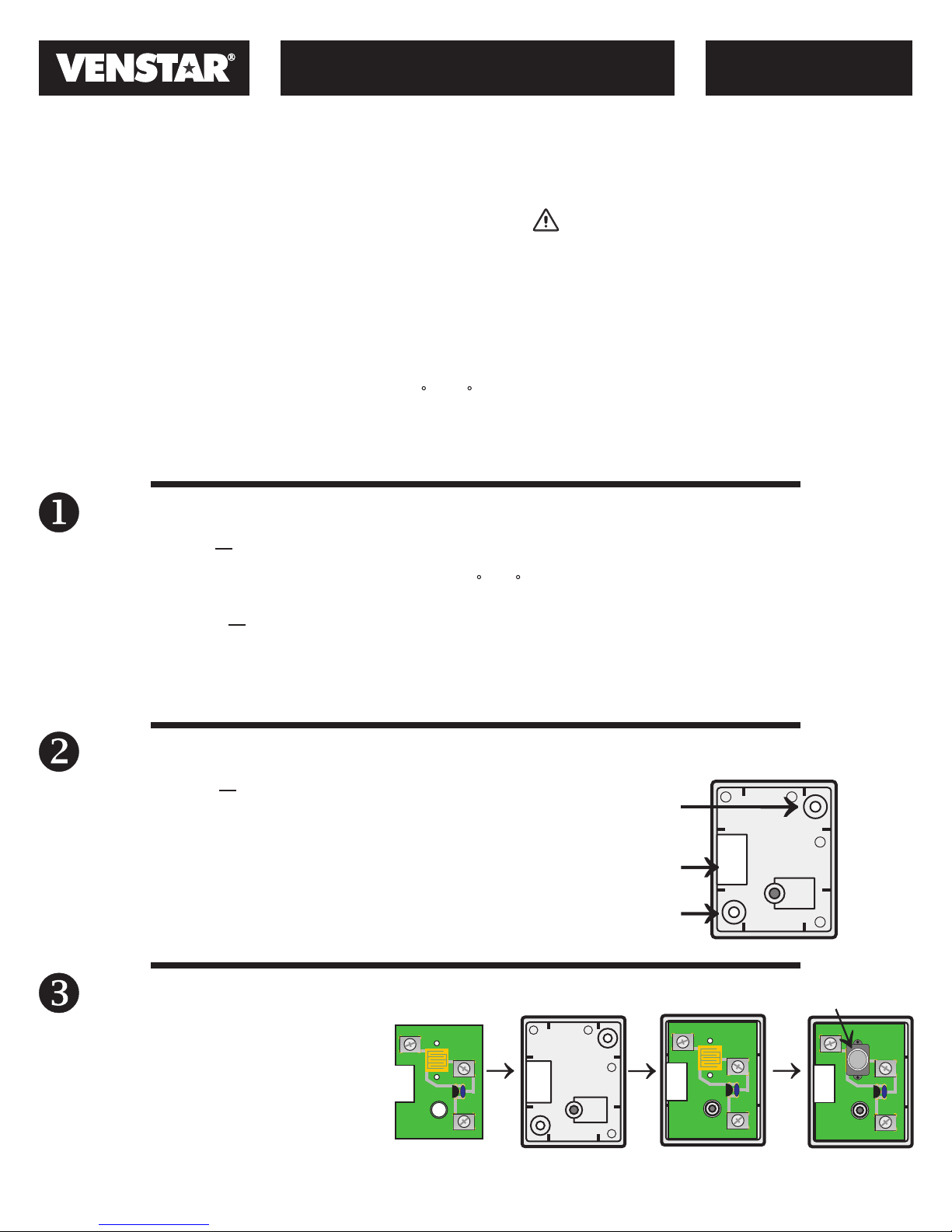
Sensor Installation
INDOOR INSTALLATION Perform the following procedures to install
the sensor:
1. Place the Remote Sensor wall plate on the wall. Mark the
mounting screw holes on the wall through the holes in the
wall plate.
2. Drill two 3/16-in. mounting holes in the wall at the location
marked in Step 1.
3. Mount the Remote Sensor wall plate to the wall with the
screws provided.
Screw hole
Through hole
for wires
Screw hole
Remote Sensor
Wall Plate
Sensor Assembly
Align and press the Remote Sensor circuit
board onto the wall plate as shown. Install the
button onto the circuit board.
Note: The OVERRIDE button can be disabled
by putting non-conductive tape over the
switch pad before installing the OVERRIDE
button onto the circuit board.
©Venstar Inc. 08/07
RS-GND
RS
RS+5
RS-GND
OVERRIDE
button
RS-GND
RS
RS+5
P/N 88-622 Rev. 1
RS
RS+5
Page 2

Wiring Requirements
REMOTE SENSOR
with OVERRIDE BUTTON
MODEL
ACC0401
The Remote Sensor should be connected to the thermostat using solid
conductor CAT 5, CAT 5e, or CAT 6 type network communication cable.
This is an unshielded cable with four twisted pairs of 24 gauge solid wire;
DO NOT use stranded cable. The cable length should not exceed 250 feet.
If less than 75 feet of cable is required to connect the thermostat to the
Remote Sensor, a three conductor thermostat cable (18-24 gauge) may be
used; this cable is NOT suitable for any length greater than 75 feet.
IMPORTANT: Do no use shielded wire. Do not run sensor wiring in the
same conduit as the 24VAC thermostat wiring. Electrical interference may
cause the sensor to give incorrect temperature readings.
Sensor Wiring
Remote Sensor
Circuit Board
RS-GND
WARNING
Turn off power to the thermostat before wiring. Death
or injury from electric shock could result.
The connection between the Remote Sensor and the
thermostat must be wired per the connection diagram.
Only three conductors are used, therefore the extra
conductors should be cut from each end of the cable to
prevent shorting. Follow the color coding as shown.
CAT 5 Cable
Thermostat Cable
RS
RS+5
Blue
Orange
Brown
Typical
Thermostat
RS+5
RS
RS-GND
Sensor Assembly
Secure the Remote Sensor top cover to the wall plate
using the supplied standard or tamper proof screws.
Multiple Sensor
Correct wiring between thermostat and remote sensor
Wiring Requirements
With the T2900 thermostat, you can
connect up to eight wired remote
sensors. Each of these sensors
must be wired in a linear or daisy
chain fashion (Fig. 1); do not use
stub connections or form a star
network (Fig.2). The thermostat
must be wired to the first remote
sensor, which is then wired to the
second remote sensor, which is
then wired to the third remote
sensor, and so on.
Fig. 1
Incorrect wiring between thermostat and remote sensor
Pm
I2:00
Su
74
COOL
AUTO
HEAT
72
I2:00
Su
AUTO
Pm
74
COOL
HEAT
72
Stubs
OVERRIDE
RS-GND
OVERRIDE OVERRIDE OVERRIDE
OVERRIDE
Pm
I2:00
Su
AUTO
RS
RS+5
OVERRIDE
OVERRIDE
74
COOL
HEAT
72
OVERRIDE
Fig. 2
NOTE: All sensor wiring must be in compliance with all applicable local and national codes.
©Venstar Inc. 08/07
Stubs
OVERRIDE OVERRIDE
OVERRIDE
Star
P/N 88-622 Rev. 1
 Loading...