

Page 1
DIGITAL OUTDOOR
TEMPERATURE SENSOR
MODEL
ACC0400
IMPORTANT: READ ALL OF THESE INSTRUCTIONS BEFORE INSTALLING THE SENSOR.
SAFETY CONSIDERATIONS
Read and follow the manufacturer instructions carefully. All wiring must conform to local and national
electrical codes. Improper wiring or installation may damage the sensor.
Recognize safety information. This is the safety alert symbol . When the safety alert symbol is present on
equipment or in the instruction manual, be alert to the potential for personal injury.
Understand the signal words DANGER, WARNING, and CAUTION. These words are used with the safety alert
symbol. DANGER identifies the most serious hazards which will result in severe personal injury or death.
WARNING signifies a hazard which could result in personal injury or death. CAUTION is used to identify
unsafe practices which may result in minor personal injury or property damage.
GENERAL
The Outdoor Sensor measures indoor or outdoor air temperature with a range of -40 to 127 F. If used indoors
as a remote temperature sensor, the sensor will read room temperature and send the information to the
thermostat. If used as an outdoor temperature sensor, the sensor may be used to provide outdoor
temperature information (which is not used to control heating or cooling).
Sensor Location
OUTDOOR LOCATION The Outdoor Sensor should be mounted on the north side of the building, out of direct sunlight,
and in a place that is protected from direct rain and snow. Mounting the sensor under an eave of a roof or under an
overhang of a building is recommended.
INDOOR LOCATION The Outdoor Sensor should be mounted approximately five feet from the floor, close to or in a
frequently used room, preferably on an inside partitioning wall or on a section of wall without pipes or ductwork. Mount
the sensor where temperature operating limits are within 32 to 99 F and where humidity operating range is within 0 to 95%
relative humidity, non-condensing.
INCORRECT LOCATIONS The Outdoor Sensor should NOT be mounted close to a window, on an outside wall, or next
to a door leading to the outside. Do not mount the sensor in a location where it would be exposed to direct light and heat
from a lamp, the sun, a fireplace, or any other temperature-radiating object which may cause a false reading. Finally, do
not mount the sensor close to or in direct airflow from supply registers or return air grilles and in areas with poor air
circulation (such as behind a door or in an alcove).
Wiring Requirements
Outdoor
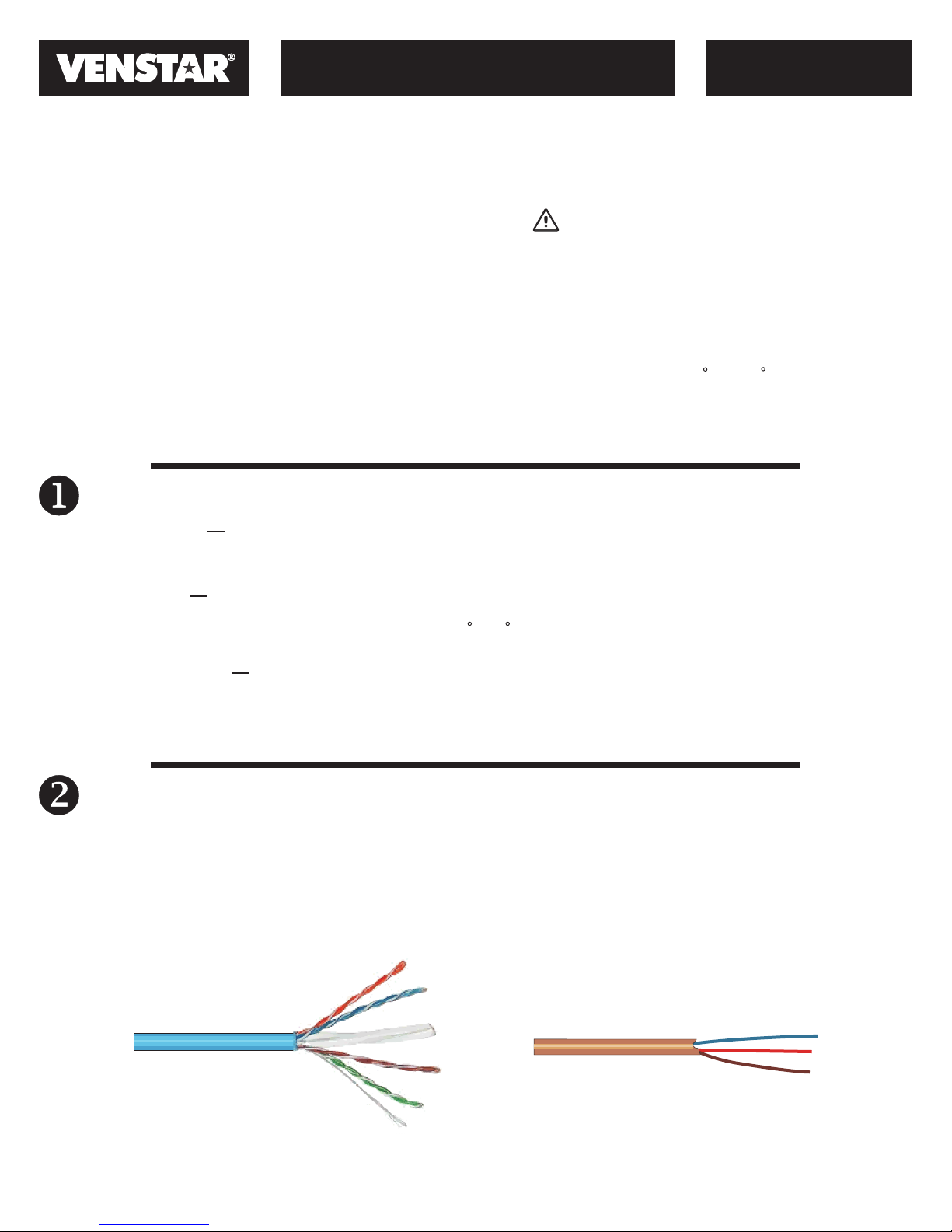
The Sensor should be connected to the thermostat using solid conductor CAT 5, CAT 5e, or CAT 6 type network
communication cable. This is an unshielded cable with four twisted pairs of 24 gauge solid wire; DO NOT use stranded
cable. The cable length should not exceed 250 feet. If less than 75 feet of cable is required to connect the thermostat to
the Outdoor Sensor, a three conductor thermostat cable (18-24 gauge) may be used; this cable is NOT suitable for any
length greater than 75 feet.
IMPORTANT: Do no use shielded wire. Do not run sensor wiring in the same conduit as the 24VAC thermostat wiring.
Electrical interference may cause the sensor to give incorrect temperature readings.
CAT 5 Cable
NOTE: All sensor wiring must be in compliance with all applicable local and national codes.
©Venstar Inc. 08/07
Thermostat Cable
P/N 88-623 Rev. 1
Page 2
DIGITAL OUTDOOR
TEMPERATURE SENSOR
MODEL
ACC0400
Sensor Wiring
Outdoor Sensor
WARNING
Turn off power to the thermostat before wiring. Death
or injury from electric shock could result.
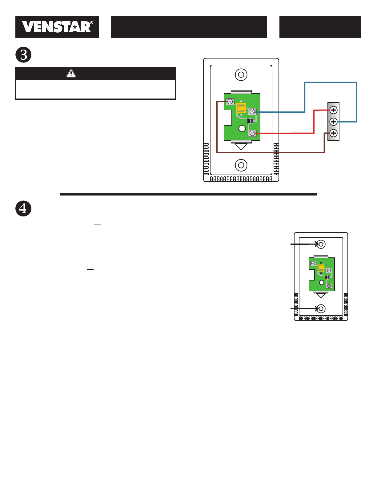
The connection between the Outdoor Sensor and the
RS-GND
RS
thermostat must be wired per the connection diagram.
Only three conductors are used, therefore the extra
conductors should be cut from each end of the cable to
RS+5
prevent shorting. Follow the color coding as shown.
DOWN
Sensor Installation
OUTDOOR INSTALLATION Perform the following procedures to install the sensor:
1. Cut a 1 x 2½-in. mounting hole in the wall.
2. Attach the mounting plate to the wall. If the Outdoor Sensor is mounted on a
rough surface, it is recommended that silicon rubber sealant be used around the
entire edge of the mounting plate. If mounting on an electrical junction box, be
sure the seal between the junction box and sensor mounting plate is tight.
INDOOR INSTALLATION Perform the following procedures to install the sensor:
1. Place the Outdoor Sensor wall plate on the wall. Mark the
mounting screw holes on the wall through the holes in
the wall plate.
2. Drill two 3/16-in. mounting holes in the wall in the location
marked in Step 1.
3. Mount the Outdoor Sensor wall plate to the wall with the
screws provided.
Blue
Orange
Brown
Screw
hole
Screw
hole
Typical
Thermostat
RS+5
RS
RS-GND
RS-GND
RS
RS+5
DOWN
©Venstar Inc. 08/07
P/N 88-623 Rev. 1
 Loading...