

Page 1
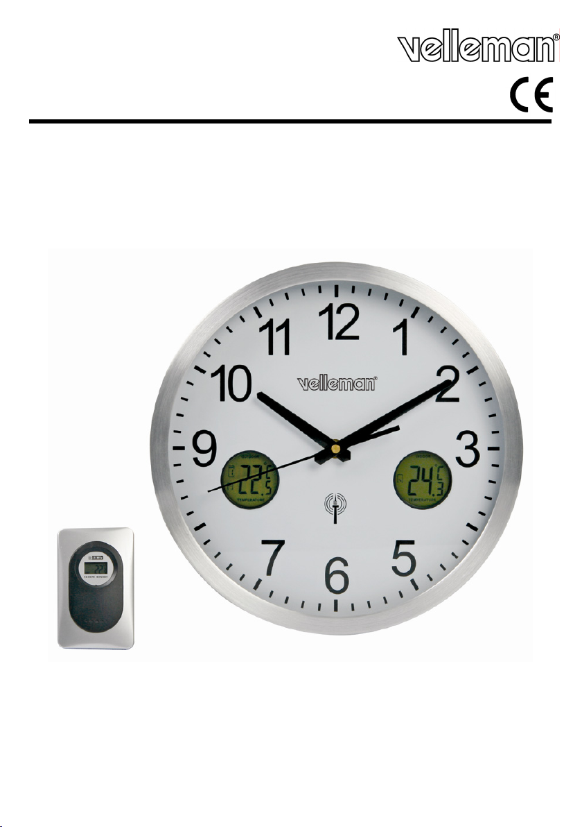
WC3320
DCF WALL CLOCK - THERMOMETER & TREND INDICATOR
DCF WANDKLOK - TEMPERATUUR EN TENDENSWEERGAVE
HORLOGE DCF MURALE - TEMPÉRATURES ET AFFICHAGE DE TENDANCE
RELOJ DCF MURAL - TEMPERATURA Y VISUALIZACIÓN DE LA TENDENCIA
DCF-WANDUHR - TEMPERATUR UND TENDENZANZEIGE
USER MANUAL 3
GEBRUIKERSHANDLEIDING 7
NOTICE D’EMPLOI 11
MANUAL DEL USUARIO 15
BEDIENUNGSANLEITUNG 19
Page 2
WC3320 Rev. 02
2
3
6
02/12/2009 ©Velleman® nv
2
Page 3
WC3320 Rev. 02
User manual
1. Introduction
To all residents of the European Union
Important environmental information about this product
If in doubt, contact your local waste disposal authorities.
Thank you for choosing Velleman! Please read the manual thoroughly before bringing this device into
service. If the device was damaged in transit, don't install or use it and contact your dealer.
2. Safety Instructions
3. General Guidelines
Refer to the Velleman® Service and Quality Warranty on the last pages of this manual.
• Protect this device from shocks and abuse. Avoid brute force when operating the device.
• Protect the device against extreme heat and dust.
• Familiarise yourself with the functions of the device before actually using it.
• All modifications of the device are forbidden for safety reasons.
• Only use the device for its intended purpose. Using the device in an unauthorised way will void the
warranty.
• Damage caused by disregard of certain guidelines in this manual is not covered by the warranty
and the dealer will not accept responsibility for any ensuing defects or problems.
• Note that damage caused by user modifications to the device is not covered by the warranty.
4. Features
• DCF controlled clock
• indoor/outdoor temperature (min, max, current)
• temperature indication: °C/°F
• temperature trend indicator
• clearly legible dial
• automatically switches between standard (winter) and daylight saving (summer) time
• with outdoor sensor
• up to 3 outdoor sensors can be connected (1 sensor included)
• spare/extra sensor: WC3320S
5. Working principle
The WC3320 contains a receiver which receives a radio-signal from a radio station located near
Frankfurt, Germany. This long-wave radio-signal (DCF77) is based on atomic clocks and contains
time and date information. The WC3320 automatically synchronizes with this master clock radiosignal and when necessary adjusts the positions of second, minute or hour hands of the clock.
Due to its nature, the radio-signal can be received indoors. However, it should be noted that the
signal is weakened by the presence of concrete and metal. Therefore the clock must not be
installed in concrete basements or inside metal cages. In large concrete office buildings or
apartments, the clock should be located near a window for better reception.
Also avoid installing the clock near strong magnetic fields or other devices that generate a lot of
electrical noise (e.g. engines).
This symbol on the device or the package indicates that disposal of the device after its
lifecycle could harm the environment. Do not dispose of the unit (or batteries) as
unsorted municipal waste; it should be taken to a specialized company for recycling.
This device should be returned to your distributor or to a local recycling service.
Respect the local environmental rules.
Keep this device away from children and unauthorized users.
Keep this device away from rain, moisture, splashing and dripping liquids.
02/12/2009 ©Velleman® nv
3
Page 4
WC3320 Rev. 02
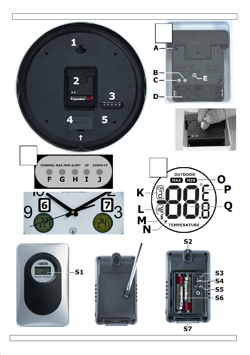
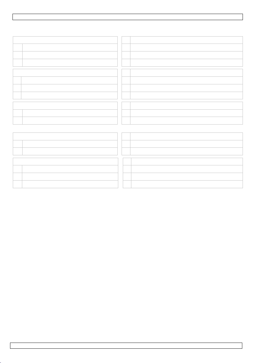
6. Overview
Refer to the illustrations on page 2 of this manual.
Clock 4 LCD battery compartment
1 suspension 5 LCD reset
2 clock movement 6 outdoor temperature/trend
3 LCD controls 7 indoor temperature/trend
Sensor S4 channel selector
S1 LCD S5 °C/°F selector
S2 suspension S6 battery compartment
S3 test button S7 foldable stand
clock movement (2) C manual set
A reset pins D battery compartment
B forced receiving E* protection pin*
* Depending on the model, this pin may or may not be present.
LCD controls (3) H alarm button
F channel selector I up-button
G max/min button J down-button and °C/°F selector
LCD display (6 & 7) N link indicator
K* channel indication O max/min indicator
L trend indicator P °C/°F indicator
M* alarm indicator Q temperature indication
* Only on the OUTDOOR display (6).
7. Clock operation
Refer to the illustrations on page 2 of this manual.
Important:
• Insert a battery in the battery compartment (see §10). All hands will move forward towards
• Choose a location for the clock (refer to §5).
• Wait until the clock receives the synchronization signal from the master clock. This might take
• Once synchronized, the hands will start moving towards the correct time.
• When the clock doesn’t receive the radio-signal, it will start running showing the wrong time.
Manual setting
• It is possible to set the time manually, e.g. for use in places where no radio-signal is received.
• Press and hold the manual set button [C]. After ±3 seconds the minutes and hour hands start
Forced receiving
• To force the clock to synchronize, press and hold the forced receiving button [B] for ±3
02/12/2009 ©Velleman® nv
Depending on the model, a protection pin may still be present to secure the movement.
Remove the protection pin before first use! Dispose of it in a safe way.
Do not attempt to reinsert the pin afterwards as this will surely damage the clock.
12:00. Note: when the original position of the second hand is between 11:55 and 12:00, the
second hand will make a full turn before stopping at 12:00. The same happens with the minute
hand when the original position is between 11:52 and 12:00.
up to 15 minutes. Note that the received signal is usually stronger at night time.
However, it will keep attempting to synchronize.
moving. Hold down the manual set button [C] and release a couple of minutes before desired
time setting. Press the manual set button [C] repeatedly until the desired time indication is
reached. When no press is detected within 7 seconds, the clock starts running.
seconds. The current time is stored in memory and all hands will start moving towards 12:00.
The clock attempts to synchronize with the master clock.
4
Page 5

WC3320 Rev. 02
• When synchronization is successful, the hands will move towards the correct time. If it fails
however, the hands will move towards the time that was memorized.
Reset
• To reset the time and memory, use a piece of metal (e.g. a blank paperclip) to short circuit the
two metal reset pins [A].
• All hands will move to the 12:00 position and the memory is cleared. The clock will attempt to
synchronize to the master clock.
8. Temperature indication
Refer to the illustrations on page 2 of this manual.
• On the clock face, there are two LCDs indicating the outdoor [6] and indoor [7] temperature
[Q] and trend [L]. The indoor temperature sensor is inside the clock housing and is refreshed
every 15s; the outdoor temperature is measured using a remote sensor which synchronizes
every 30s.
Remote sensor
• Make sure batteries are present inside the remote sensor and LCD battery compartment (see §10).
• Release the screw on the back of the remote sensor and set the channel selector [S4] to the
desired channel (1~3). The channel is indicated on the LCD [S1].
Note: when multiple sensors are used they must be set to different channels.
• Set the same channel on the clock using the channel selector [F]. The channel is shown [K] on
the outdoor display [6].
• Press the test button [S3] to test the link between the sensor and the clock. When everything
works fine, the link indicator [N] on the LCD [6] lights up briefly and the clock will beep once.
• Press the °C/°F selector [S5] to set the temperature scale on the remote LCD [S1] to °C or °F.
Note: this setting is only applicable for the temperature indication on the remote sensor itself,
not on the clock.
• Close the back of the sensor and secure it with the screw.
• The sensor can be used freestanding by unfolding the foldable stand [S7] or hung on the wall
by the suspension [S2]. Always placed the sensor in a location protected from rain, moisture,
splashing and dripping liquids.
General
• Set the temperature scale to °C or °F by pressing the °C/°F selector [J]. The scale is indicated
on the display [P]. Note that the setting is applicable for both indoor and outdoor temperature
indications.
• The temperature trend [L] (rising, steady, decreasing) is shown for both indoor [7] and outdoor
temperatures [6].
• To see the maximum measured temperature since last reset, press the max/min button [G]
once. Press again to see the minimum temperature since last reset.
• Press the max/min button [G] a third time to see the current temperature. Note: the
temperature indication returns to current temperature automatically after ±8 seconds.
• To reset the maximum and minimum values, press and hold the max/min button [G] for ±2s.
• When multiple sensors are used (max. 3, only 1 sensor included), press the channel selector [F]
to switch between the different remote sensors.
• To re-initialize the temperature indication completely (clear all limits and max/min values for all
channels) use a small pin (e.g. a paper clip) to press briefly on the reset button [5].
Alarm setting
• The clock can generate an alarm when a preset upper or lower temperature limit is reached.
These limits can be set individually for the 3 available sensor channels.
• Press and hold the alarm button [H] for ±2s. The upper temperature limit value and indicator
[M] start flashing on the LCD [6] (default: +70°C/ +158°F).
• When no key is touched within ±5s, the LCD will resume normal operation.
• Use the up [I] and/or down [J] button to set the desired upper temperature limit. Press and
hold the buttons will increase setting speed.
• When multiple sensors (channels) are used, press the channel button [F] to move to the next
channel and set its desired upper temperature limit.
• Press the alarm button [H] again to store the setting. The lower temperature limit value and
indicator [M] start flashing on the LCD [6] (default: -50°C/ -58°F).
02/12/2009 ©Velleman® nv
5
Page 6
WC3320 Rev. 02
• Use the up [I] and/or down [J] button to set the desired lower temperature limit. Press and
hold the buttons will increase setting speed.
• When multiple sensors (channels) are used, press the channel button [F] to move to the next
channel and set its desired lower temperature limit.
• Press the alarm button [H] again to store the setting and return to normal mode.
• Press the alarm button [H] shortly to switch the alarm on or off; when the alarm indicator [M]
is shown, the alarm is enabled.
• When the set upper or lower limit is reached, the clock will generate an alarm sound and the
temperature indication starts flashing. Press the alarm button [H] to switch off the alarm.
Note: the alarm will switch on or off for all channels simultaneously.
9. Maintenance
• Wipe the clock and sensor regularly with a moist, lint-free cloth. Do not use alcohol or solvents.
10. Batteries
Clock
• Insert a new 1.5V AA battery in the battery compartment in accordance with the polarity
markings inside the battery compartment.
Temperature display
• Push on the small tab (see arrow) to open the battery compartment [4].
• Insert two new 1.5V AA batteries in the battery compartment [4] in accordance with the
polarity markings inside the battery compartment.
• Snap the battery cover back in place.
Remote sensor
• Release the screw at the back of the remote sensor an open the battery compartment.
• Insert two new 1.5V AAA batteries in the battery compartment [4] in accordance with the
polarity markings inside the battery compartment.
• After replacing the batteries on the remote sensor, press and hold the channel button [F] for
±2s to clear all previous sensor data. Than press the test button [S3] on the remote senor to
re-establish connection.
• Close the back of the sensor and secure it with the screw.
11. Technical specifications
temperature range
frequency 433MHz
power supply
dimensions
weight
Use this device with original accessories only. Velleman nv cannot be held responsible
in the event of damage or injury resulted from (incorrect) use of this device. For more
info concerning this product, please visit our website www.velleman.eu. The
information in this manual is subject to change without prior notice.
© COPYRIGHT NOTICE
This manual is copyrighted. The copyright to this manual is owned by Velleman nv. All
worldwide rights reserved. No part of this manual may be copied, reproduced, translated or
reduced to any electronic medium or otherwise without the prior written consent of the copyright
holder.
02/12/2009 ©Velleman® nv
WARNING:
Dispose of batteries in accordance with local regulations.
Keep batteries away from children.
indoor 0°C~50°C
outdoor -20 ~60°C
clock 3 x 1.5V AA batteries (LR6C, not incl.)
sensor 2 x 1.5V AAA batteries (LR03C, not incl.)
clock Ø30x4cm
sensor 25x60x95mm
clock ±865g
sensor ±65g
6
Page 7
WC3320 Rev. 02
GEBRUIKERSHANDLEIDING
1. Inleiding
Aan alle ingezetenen van de Europese Unie
Belangrijke milieu-informatie betreffende dit product
Hebt u vragen, contacteer dan de plaatselijke autoriteiten betreffende de verwijdering.
Dank u voor uw aankoop! Lees deze handleiding grondig voor u het toestel in gebruik neemt.
Werd het toestel beschadigd tijdens het transport, installeer het dan niet en raadpleeg uw dealer.
2. Veiligheidsinstructies
3. Algemene richtlijnen
Raadpleeg de Velleman® service- en kwaliteitsgarantie achteraan deze handleiding.
• Bescherm de klok tegen schokken. Vermijd brute kracht tijdens de bediening.
• Leer eerst de functies van het toestel kennen voor u het gaat gebruiken.
• Om veiligheidsredenen mag u geen wijzigingen aanbrengen.
• Gebruik het toestel enkel waarvoor het gemaakt is. Bij onoordeelkundig gebruik vervalt de
• De garantie geldt niet voor schade door het negeren van bepaalde richtlijnen in deze
• Schade door wijzigingen die de gebruiker heeft aangebracht valt niet onder de garantie.
4. Eigenschappen
• wandklok met DCF-sturing
• binnen-/buitentemperatuur (min, max, huidig)
• temperatuurweergave: °C/°F
• weergave van de temperatuurtendens
• grote en duidelijk leesbare wijzerplaat
• automatische overschakeling naar zomer-/wintertijd
• buitensensor
• aansluitmogelijkheid voor 3 buitensensoren (1 sensor meegelev.)
• extra sensor / reservesensor: WC3320S
5. Wat is het DCF-signaal?
De WC3320 bevat een ontvanger die de radiografische signalen (DCF77) door de tijdseinzender
in Frankfurt uitgezonden kan ontvangen. De tijdseinzender is gekoppeld aan een atoomklok die de
tijd- en datuminformatie bevat. Uw WC3320 zal bij ontvangst van het DCF-signaal de wijzers
automatisch met de atoomklok synchroniseren.
Het radiosignaal is gemakkelijk binnenshuis te ontvangen. De ontvangst kan echter verzwakken
indien er beton en metaal aanwezig is. Het is daarom niet aan te raden om de klok te installeren
in kelders en binnenin een metalen kooi. De beste locatie om de klok op kantoor of op een flat te
installeren, is naast een raam.
Vermijd ook installatie in de buurt van magnetische velden of apparaten die elektrische ruis
voortbrengen (bv. een motor).
Dit symbool op het toestel of de verpakking geeft aan dat, als het na zijn levenscyclus
wordt weggeworpen, dit toestel schade kan toebrengen aan het milieu. Gooi dit toestel
(en eventuele batterijen) niet bij het gewone huishoudelijke afval; het moet bij een
gespecialiseerd bedrijf terechtkomen voor recyclage. U moet dit toestel naar uw verdeler
of naar een lokaal recyclagepunt brengen. Respecteer de plaatselijke milieuwetgeving.
Houd buiten het bereik van kinderen en onbevoegden.
Bescherm tegen regen, vochtigheid, stof, extreme temperaturen en opspattende
vloeistoffen.
garantie.
handleiding en uw dealer zal de verantwoordelijkheid afwijzen voor defecten of problemen die
hier rechtstreeks verband mee houden.
02/12/2009 ©Velleman® nv
7
Page 8
WC3320 Rev. 02
6. Overzicht
Raadpleeg de figuren op pagina 2 van deze handleiding.
Klok 4 batterijvak lcd-scherm
1 ophangoogje 5 resetknop lcd-scherm
2 mechanisme 6 buitentemperatuur/tendens
3 instelknoppen lcd-scherm 7 binnentemperatuur/tendens
Sensor S4 selectieknop kanaal
S1 lcd-scherm S5 selectieknop °C/°F
S2 ophangoogje S6 batterijvak
S3 testknop S7 statief
Mechanisme (2) C handmatige instelling
A resetpinnen D batterijvak
B gedwongen ontvangst E* veiligheidspin*
* Afhankelijk van het model is deze pin aanwezig of niet.
Instelknoppen lcd-scherm (3) H alarmknop
F selectieknop kanaal I UP
G selectieknop max./min. J DOWN + selectieknop °C/°F
Lcd-scherm (6 & 7) N ontvangstweergave
K* kanaalweergave O weergave max./min.
L trendweergave P weergave °C/°F
M* alarmweergave Q temperatuurweergave
* Enkel op het lcd-scherm voor buitentemperatuur (6).
7. Gebruik
Raadpleeg de figuren op pagina 2 van deze handleiding.
Belangrijk: Afhankelijk van het model is het mechanisme beveiligd met een veiligheidspin.
• Plaats een batterij in het batterijvak (zie §10). Alle wijzers plaatsen zich automatisch op 12:00.
Opmerking: wanneer de seconde- of de minutenwijzer tussen 11:52 en 12:00 staat, zal hij
eerst een volledige omwenteling maken alvorens zich op 12:00 te plaatsen.
• Kies een geschikte installatieplaats (zie §5).
• Wacht tot de klok het DCF-signaal ontvangt. Dit kan tot 15 minuten duren. Het DCF-signaal is
meestal sterker ’s nachts.
• Eenmaal de klok is gesynchroniseerd, zullen de wijzers zich op het correcte uur plaatsen.
• Indien de klok het signaal niet kan ontvangen, zal deze toch lopen. De klok blijft het DCF-
signaal proberen te ontvangen.
Handmatige instelling
• Stel de klok handmatig in indien er geen DCF-signaal kan ontvangen worden.
• Houd de instelknop [C] ingedrukt. Na ± 3 seconden verplaatsen de wijzers zich. Laat de
instelknop [C] los enkele minuten vóór de juiste tijd. Druk nu de instelknop [C] herhaaldelijk in
tot de klok de juiste tijd weergeeft. De klok loopt 7 seconden na de laatste druk op een knop.
Gedwongen ontvangst
• Houd de ontvangstknop [B] gedurende ± 3 seconden ingedrukt om de klok te dwingen om zich
te synchroniseren. De aangeduide tijd wordt in het geheugen opgeslagen en de wijzers
verplaatsen zich naar 12:00. De klok probeert zich nu te synchroniseren.
Verwijder de veiligheidspin voor de eerste ingebruikname! Steek deze pin nooit terug
in het gaatje om onherroepelijke schade te vermijden.
02/12/2009 ©Velleman® nv
8
Page 9

WC3320 Rev. 02
• Na de synchronisatie verplaatsen de wijzers zich naar de correcte tijd. Bij niet-synchronisatie
verplaatsen de wijzers zich naar het eerder opgeslagen uur.
De klok resetten
• Veroorzaak een kortsluiting tussen de twee metalen pinnetjes [A] met behulp van een metalen
object, bv. een paperclip.
• De wijzers verplaatsen zich naar 12:00 en het geheugen wordt gewist. De klok zal zich daarna
opnieuw met het DCF-signaal proberen te synchroniseren.
8. Temperatuursweergave
Raadpleeg de figuren op pagina 2 van deze handleiding.
• Op de wijzerplaat staan twee lcd-schermpjes. Het linkerscherm [6] geeft de buitentemperatuur
[Q] en –trend [L] aan, het rechterscherm [7] geeft de binnentemperatuur [Q] en –trend [L]
aan. De binnentemperatuur wordt om de 15 seconden geüpdatet, de buitentemperatuur wordt
om de 30 seconden gemeten via de buitensensor.
Buitensensor
• Plaats de batterijen in de sensor en de batterijvakken (zie §10).
• Selecteer een kanaal (1 ~ 3) via de selectieknop [S4]. Het kanaal wordt op het lcd-scherm
[S1] weergegeven.
Opmerking: Kies voor elke gebruikte sensor een afzonderlijk kanaal.
• Selecteer nu hetzelfde kanaal op de klok via de selectieknop [F]. Het kanaal [K] wordt op het
lcd-scherm [6] weergegeven.
• Druk op de testknop [S3] om de ontvangst tussen de klok en de sensor te testen. Bij een goede
ontvangst verschijnt een symbool [N] op het lcd-scherm [6] en zal de klok eenmaal piepen.
• Druk op de selectieknop °C/°F [S5] om de meeteenheid op de sensor [S1] te selecteren.
Opmerking: Enkel geldig voor de meeteenheid op de sensor en niet voor die op de klok zelf.
• Sluit het batterijvak en draai de schroef vast.
• Vouw het statief open [S7] of hang de sensor aan de muur via het gaatje [S2]. Bescherm de
sensor tegen regen, vochtigheid en opspattende vloeistoffen.
Algemeen
• Selecteer de meeteenheid (°C/°F) via de selectieknop [J]. Uw keuze wordt op het lcd-scherm
[P] weergegeven. Doe dit voor zowel de binnen- als de buitentemperatuur.
• De temperatuurverwachting [L] (stijgen, stabiel, dalen) wordt op beide lcd-schermen [6, 7]
weergegeven.
• Druk eenmaal op MAX/MIN [G] om de maximumtemperatuur weer te geven, druk een tweede
maal om de minimumtemperatuur weer te geven, druk een derde maal om de huidige
temperatuur weer te geven.
Opmerking: De huidige temperatuur verschijnt automatisch na 8 seconden.
• Reset de temperatuurwaarden door MAX/MIN [G] gedurende 2 seconden ingedrukt te houden.
• Druk op de selectieknop [F] om de sensor te selecteren (max. 3, 1 sensor meegeleverd).
• Druk met een paperclip de resetknop [5] kort in om alle temperatuurwaarden (alle limieten en
minimum- en maximumwaarden voor alle sensoren) te resetten.
Alarminstelling
• De klok kan een alarm genereren wanneer de geprogrammeerde temperatuurlimieten
overschreden zijn. U kunt voor elke sensor afzonderlijke limieten programmeren.
• Houd de alarmknop [H] gedurende 2 seconden ingedrukt. De waarde voor de bovenlimiet en de
aanduiding [M] knipperen op het lcd-scherm [6] (standaard: +70°C/+158°F).
• Het lcd-scherm keert terug naar de normale weergave na ongeveer 5 seconden.
• Stel de bovenlimiet in met UP [I] en DOWN [J].
• Selecteer nu de volgende sensor met de selectieknop [F] indien van toepassing en stel de
bovenlimiet in voor deze sensor.
• Druk op alarmknop [H] om de instelling te bewaren. De waarde voor de onderlimiet en de
aanduiding [M] knipperen op het lcd-scherm [6] (standaard: -50°C/-58°F).
• Stel de onderlimiet in met UP [I] en DOWN [J].
• Selecteer nu de volgende sensor met de selectieknop [F] indien van toepassing en stel de
onderlimiet in voor deze sensor.
• Druk op alarmknop [H] om de instelling te bewaren. Het lcd-scherm keert terug naar de
normale weergave.
02/12/2009 ©Velleman® nv
9
Page 10

WC3320 Rev. 02
• Druk kort op de alarmknop [H] om het alarm in of uit te schakelen. Het alarm is ingeschakeld
wanneer de aanduiding [M] op het lcd-scherm verschijnt.
• Van zodra de omgevingstemperatuur een ingestelde limietwaarde bereikt, zal de klok een alarm
genereren. De aanduiding zal op het lcd-scherm knipperen. Druk op de alarmknop [H] om het
alarm uit te schakelen.
Opmerking: Het alarm wordt op alle sensoren in- of uitgeschakeld.
9. Onderhoud
• Maak de wandklok en sensor regelmatig schoon met een vochtige, niet-pluizende doek. Gebruik
geen alcohol of solventen.
10. De batterijen
Klok
• Plaats drie 1,5 V AA-batterijen in het batterijvak volgens de polariteitaanduidingen.
Temperatuurweergave
• Open het batterijvak [4].
• Plaats twee 1,5 V AA-batterijen in het batterijvak volgens de polariteitaanduidingen.
• Sluit het batterijvak.
Sensor
• Draai de schroef van het batterijvak los en open het batterijvak.
• Plaats twee 1,5 V AAA-batterijen in het batterijvak volgens de polariteitaanduidingen.
• Houd daarna de selectieknop [F] gedurende 2 seconden ingedrukt om alle data te wissen. Druk
op de testknop [S3] om de ontvangst te testen.
• Sluit het batterijvak.
WAARSCHUWING: Houd de batterijen buiten het bereik van kinderen.
11. Technische specificaties
temperatuurbereik
frequentie 433 MHz
voeding
afmetingen
gewicht
Gebruik dit toestel enkel met originele accessoires. Velleman nv is niet aansprakelijk voor
schade of kwetsuren bij (verkeerd) gebruik van dit toestel. Voor meer informatie over dit
product, zie www.velleman.eu. De informatie in deze handleiding kan te allen tijde worden
gewijzigd zonder voorafgaande kennisgeving.
© AUTEURSRECHT
Velleman nv heeft het auteursrecht voor deze handleiding.
Alle wereldwijde rechten voorbehouden. Het is niet toegestaan om deze handleiding of gedeelten
ervan over te nemen, te kopiëren, te vertalen, te bewerken en op te slaan op een elektronisch
medium zonder voorafgaande schriftelijke toestemming van de rechthebbende.
binnentemperatuur 0°C~50°C
buitentemperatuur -20 ~60°C
wandklok 3 x 1,5 V AA-batterijen LR6C, niet meegelev.)
sensor 2 x 1,5 V AAA-batterijen LR03C, niet meegelev.)
wandklok Ø 30 x 4 cm
sensor 25 x 60 x 95 mm
wandklok ± 865 g
sensor ± 65 g
02/12/2009 ©Velleman® nv
10
Page 11

WC3320 Rev. 02
NOTICE D’EMPLOI
1. Introduction
Aux résidents de l'Union européenne
Des informations environnementales importantes concernant ce produit
En cas de questions, contacter les autorités locales pour élimination.
Nous vous remercions de votre achat ! Lire la présente notice attentivement avant la mise en
service de l’appareil. Si l’appareil a été endommagé pendant le transport, ne pas l’installer et
consulter votre revendeur.
2. Consignes de sécurité
3. Directives générales
Se référer à la garantie de service et de qualité Velleman® à la fin de cette notice.
• Protéger contre les chocs et le traiter avec circonspection pendant l’opération.
• Se familiariser avec le fonctionnement avant l’emploi.
• Toute modification est interdite pour des raisons de sécurité.
• N’utiliser qu’à sa fonction prévue. Un usage impropre annule d'office la garantie.
• La garantie ne s’applique pas aux dommages survenus en négligeant certaines directives de
cette notice et votre revendeur déclinera toute responsabilité pour les problèmes et les défauts
qui en résultent.
• Les dommages occasionnés par des modifications par le client ne tombent pas sous la garantie.
4. Caractéristiques
• horloge radiopilotée via le signal DCF
• températures intérieure/extérieure (min, max, actuelle)
• affichage de température : °C/°F
• affichage de la tendance de température
• cadran grand format clairement lisible
• commutation automatique vers l'heure d'été/d'hiver
• capteur extérieur
• possibilité de connexion pour 3 capteurs (1 capteur incl.)
• capteur additionnel / de rechange : WC3320S
5. Principe de fonctionnement
La WC3320 intègre un récepteur qui capte le signal DCF transmit par l’émetteur situé près de
Francfort en Allemagne. Cet émetteur est connecté à une horloge atomique qui contient les
données de temps et de date. La WC3320 se synchronise automatiquement sur l’horloge
atomique afin de régler les aiguilles.
Ce signal radio est parfaitement captable à l’intérieur d’un immeuble. Sa puissance sera
cependant affaiblie par la présence de béton et de métal. Il est donc préférable de ne pas monter
l’horloge dans des caves ou dans un endroit sur-isolé. L’endroit le plus approprié dans un bureau
ou un appartement en béton est près d’une fenêtre.
Il est également déconseillé d’installer l’horloge à proximité d’un champ magnétique ou d’un
appareil générant un bruit électrique (p.ex. un moteur).
Ce symbole sur l'appareil ou l'emballage indique que l’élimination d’un appareil en fin
de vie peut polluer l'environnement. Ne pas jeter un appareil électrique ou électronique
(et des piles éventuelles) parmi les déchets municipaux non sujets au tri sélectif ; une
déchèterie traitera l’appareil en question. Renvoyer les équipements usagés à votre
fournisseur ou à un service de recyclage local. Il convient de respecter la
réglementation locale relative à la protection de l’environnement.
Garder hors de la portée des enfants et des personnes non autorisées.
Protéger contre la pluie, l’humidité, la poussière, les températures extrêmes et les
projections d’eau.
02/12/2009 ©Velleman® nv
11
Page 12

WC3320 Rev. 02
6. Description
Se référer aux illustrations à la page 2 de cette notice.
Horloge 4 compartiment des piles pour l’afficheur LCD
1 crochet de suspension 5 bouton de réinitialisation pour l’afficheur LCD
2 mouvement 6 température/tendance extérieures
3 commandes de l’afficheur LCD 7 température/tendance intérieures
Capteur S4 sélecteur de canal
S1 afficheur LCD S5 sélecteur °C/°F
S2 crochet de suspension S6 compartiment des piles
S3 bouton de test S7 socle
Mouvement (2) C réglage manuel
A broches de réinitialisation D compartiment de la pile
B réception forcée E* ergot de verrouillage*
* Présence d’un ergot selon les modèles.
Commandes de l’afficheur LCD (3) H bouton de l’alarme
F sélecteur de canal I bouton UP
G sélecteur MAX/MIN J bouton DOWN/sélecteur °C/°F
Afficheur LCD (6 & 7) N affichage de transmission
K* affichage du canal O affichage MAX/MIN
L affichage de la tendance P affichage °C/°F
M* affichage de l’alarme Q affichage de la température
* Uniquement sur l’afficheur extérieur (6).
7. Emploi
Se référer aux illustrations à la page 2 de cette notice.
Important : Un ergot de verrouillage est présent suivant le modèle d’horloge. Retirer l’ergot de
• Insérer la pile dans le compartiment (voir §10). Toutes les aiguilles se déplaceront vers 12:00.
Remarque : la trotteuse et la grande aiguille feront un tour de cadran complet lorsqu’elles se
situent entre 11:52 et 12:00.
• Choisir l’endroit d’installation (voir §5).
• Patienter jusqu’à ce que l’horloge se soit synchronisée. Ceci peut durer jusqu’à 15 minutes.
Remarque : le signal est généralement plus puissant la nuit.
• Une fois l’horloge synchronisée, les aiguilles se déplaceront vers l’heure exacte.
• Lors d’un signal de réception trop faible, l’horloge se met en marche en indiquant l’heure
inexacte. Elle continuera d’essayer de se synchroniser.
Réglage manuel
• Régler l’heure manuellement lors d’un signal de réception trop faible.
• Maintenir enfoncé le bouton de réglage manuel [C]. Les aiguilles se déplacent après ± 3
secondes. Relâcher le bouton quelques minutes avant l’heure exacte. À présent, enfoncer le
bouton de réglage manuel [C] à plusieurs reprises jusqu’à ce que l’horloge affiche l’heure
exacte. L’horloge se met en marche 7 secondes après le dernier réglage.
Réception forcée
• Pour effectuer une synchronisation forcée, maintenir enfoncé le bouton de réception [B]
pendant ± 3 secondes. L’heure affichée sera mise en mémoire et toutes les aiguilles se
déplaceront vers 12:00. L’horloge tentera la synchronisation avec l’horloge atomique.
• Une fois l’horloge synchronisée, les aiguilles afficheront l’heure exacte. Dans le cas contraire,
l’horloge affichera l’heure préalablement mémorisée.
02/12/2009 ©Velleman® nv
verrouillage avant le premier emploi ! Ne jamais le réinsérer afin d’éviter
l’endommagement irrévocable de l’horloge.
12
Page 13

WC3320 Rev. 02
Réinitialisation
• Réinitialiser l’horloge et effacer la mémoire en court-circuitant les deux broches [A] avec un
objet métallique (p.ex. un trombone).
• Les aiguilles se déplacent vers 12:00 et la mémoire est effacée. L’horloge tentera la
synchronisation avec l’horloge atomique.
8. Affichage de la température
Se référer aux illustrations à la page 2 de cette notice.
• Le cadran affiche deux afficheurs LCD indiquant les températures [Q] et tendances [L]
extérieure [6] et intérieure [7]. L’affichage de la température intérieure est mis à jour toutes
les 15 secondes ; l’affichage de la température extérieure est synchronisé toutes les 30
secondes.
Capteur
• Insérer les piles dans le capteur et dans l’horloge (voir §10).
• Ouvrir le compartiment des piles et sélectionner le canal (1 ~ 3) avec le sélecteur [S4]. Le
canal s’affiche sur l’afficheur [S1].
Remarque : Sélectionner un canal pour chaque capteur utilisé.
• Sélectionner le canal sur l’horloge avec le sélecteur [F]. Le canal [K] s’affiche sur l’afficheur
[6].
• Enfoncer le bouton de test [S3] pour établir la connexion entre le capteur et l’horloge. Le
symbole [N] s’affiche et l’horloge émet une tonalité lors d’une bonne réception.
• Enfoncer le sélecteur °C/°F [S5] pour sélectionner l’unité de mesure [S1].
Remarque : Uniquement valable pour l’afficheur du capteur.
• Refermer le compartiment des piles.
• Le capteur peut être utilisé en pose libre en déployant le socle [S7] ou accroché au mur [S2].
Veiller à installer le capteur dans un endroit protégé de la pluie, de l’humidité et des projectiosn
d’eau.
En général
• Sélectionner l’unité de mesure °C ou °F avec le sélectionneur [J]. L’unité sélectionnée s’affiche
[P] et est valable pour les températures intérieure et extérieure.
• La tendance [L] (hausse, stabilité, baisse) s’affiche pour les températures intérieure [7] et
extérieure [6].
• Afficher la température maximale enregistrée en enfonçant le bouton MAX/MIN [G]. Renfoncer
le bouton pour afficher la température minimale enregistrée. Renfoncer le bouton une troisième
fois pour afficher la température ambiante actuelle.
Remarque : L’afficheur revient à l’affichage normal après environ 8 secondes.
• Remettre les valeurs enregistrées à zéro en maintenant enfoncé le bouton MAX/MIN [G]
pendant 2 secondes.
• Sélectionner le capteur suivant (max. 3 capteurs, 1 capteur inclus) avec le sélecteur [F].
• Réinitialiser les afficheurs de température (effacement des limites et des valeurs max/min de
tous les capteurs) en enfonçant le bouton de réinitialisation [5] à l’aide d’un trombone.
Paramétrage de l’alarme
• L’horloge émettra une tonalité dès qu’une limite a été atteinte. Il est possible de programmer
des limites pour chaque capteur utilisé.
• Maintenir enfoncé le bouton d’alarme [H] pendant 2 secondes. La valeur de limite supérieure et
l’indication [M] clignotent sur l’afficheur [6] (valeur par défaut : +70°C/+158°F).
• L’afficheur revient à l’affichage normal après 5 secondes.
• Programmer la valeur de limite supérieure avec UP [I] et DOWN [J].
• Sélectionner le capteur suivant avec le sélecteur [F] si nécessaire et programmer la valeur de
limite supérieure.
• Maintenir enfoncé le bouton d’alarme [H] pendant 2 secondes. La valeur de limite inférieure et
l’indication [M] clignotent sur l’afficheur [6] (valeur par défaut : -50°C/-58°F).
• Programmer la valeur de limite inférieure avec UP [I] et DOWN [J].
• Sélectionner le capteur suivant avec le sélecteur [F] si nécessaire et programmer la valeur de
limite inférieure.
• Renfoncer le bouton d’alarme [H] pour sauvegarder les valeurs. L’afficheur revient à l’affichage
normal.
02/12/2009 ©Velleman® nv
13
Page 14
WC3320 Rev. 02
• Enfoncer brièvement le bouton d’alarme [H] pour activer/désactiver l’alarme. L’alarme est
activée lorsque l’indication [M] est affichée.
• L’horloge émettra une tonalité et l’affichage de la température clignotera dès qu’une limite a été
atteinte. Désactiver l’alarme avec le bouton d’alarme [H].
Remarque : L’alarme est activée/désactivé simultanément sur tous les capteurs.
9. Entretien
• Nettoyer l’horloge et le capteur régulièrement avec un chiffon doux et non pelucheux. Éviter
l’utilisation d’alcools et de solvants.
10. La pile
L’horloge
• Insérer une pile 1,5 V type R6 dans le compartiment selon les indications de polarité.
L’affichage de température
• Ouvrir le compartiment des piles [4].
• Insérer deux piles 1,5 V type R6 dans le compartiment selon les indications de polarité.
• Refermer le compartiment des piles.
Le capteur
• Desserrer la vis à l’arrière et ouvrir le compartiment des piles.
• Insérer deux piles 1,5 V type R03 dans le compartiment selon les indications de polarité.
• Ensuite, maintenir enfoncé le sélecteur de canal [F] pendant 2 secondes pour effacer toutes les
données enregistrées préalablement. Enfoncer le bouton de test [S3] pour rétablir la connexion.
• Refermer le compartiment des piles et resserrer la vis.
ATTENTION : Garder les piles hors de la portée des enfants.
11. Spécifications techniques
plage de température
fréquence 433MHz
alimentation
dimensions
poids
N’employer cet appareil qu’avec des accessoires d’origine. SA Velleman ne sera
aucunement responsable de dommages ou lésions survenus à un usage (incorrect) de
cet appareil. Pour plus d’information concernant cet article, visitez notre site web
www.velleman.eu. Toutes les informations présentées dans cette notice peuvent être
modifiées sans notification préalable.
© DROITS D’AUTEUR
SA Velleman est l’ayant droit des droits d’auteur pour cette notice.
Tous droits mondiaux réservés. Toute reproduction, traduction, copie ou diffusion, intégrale ou
partielle, du contenu de cette notice par quelque procédé ou sur tout support électronique que se
soit est interdite sans l’accord préalable écrit de l’ayant droit.
température intérieure 0°C~50°C
température extérieure -20 ~60°C
horloge 3 piles 1,5 V type R6 (LR6C, non incl.)
capteur 2 piles 1,5 V type R03 (LR03C, non incl.)
horloge Ø 30 x 4 cm
capteur 25 x 60 x 95 mm
horloge ± 865 g
capteur ± 65 g
02/12/2009 ©Velleman® nv
14
Page 15

WC3320 Rev. 02
MANUAL DEL USUARIO
1. Introducción
A los ciudadanos de la Unión Europea
Importantes informaciones sobre el medio ambiente concerniente a este producto
Si tiene dudas, contacte con las autoridades locales para residuos.
¡Gracias por haber comprado el WC3320! Lea atentamente las instrucciones del manual antes de
usarlo. Si el aparato ha sufrido algún daño en el transporte no lo instale y póngase en contacto
con su distribuidor.
2. Instrucciones de seguridad
3. Normas generales
Véase la Garantía de servicio y calidad Velleman ® al final de este manual del usuario.
• No agite el aparato. Evite usar excesiva fuerza durante el manejo y la instalación.
• Familiarícese con el funcionamiento del aparato antes de utilizarlo.
• Por razones de seguridad, las modificaciones no autorizadas del aparato están prohibidas.
• Utilice sólo el aparato para las aplicaciones descritas en este manual. Su uso incorrecto anula la
• Los daños causados por descuido de las instrucciones de seguridad de este manual invalidarán
• Los daños causados por modificaciones no autorizadas, no están cubiertos por la garantía.
4. Características
• reloj radiocontrolado por la señal DCF
• temperatura interior/exterior (mín., máx., actual)
• visualización de la temperatura: °C/°F
• visualización de la tendencia de la temperatura
• esfera claramente legible
• cambia automáticamente de hora de verano a hora de invierno
• sensor exterior
• es posible conectar hasta 3 sensores (1 sensor incl.)
• sensor adicional / de recambio: WC3320S
5. Principio de funcionamiento
El WC3320 incorpora un receptor que capta la señal DCF transmitida por el emisor situado cerca
de Francfort en Alemania. Este emisor está conectado a un reloj atómico que contiene los datos
de tiempo y fecha. El WC3320 se sincroniza automáticamente con el reloj atómico para ajustar
las agujas.
Es posible captar esta señal radio de forma perfecta en el interior de un edificio. Sin embargo, su
potencia se debilita a causa de hormigón y metal. Por tanto, no monte el reloj en sótanos o un
lugar demasiado aislado. El lugar más adecuado en una oficina o un apartamiento de hormigón es
cerca de una ventana.
No instale el reloj cerca de un campo magnético o un aparato que genera un ruido eléctrico (p.ej.
un motor).
02/12/2009 ©Velleman® nv
Este símbolo en este aparato o el embalaje indica que, si tira las muestras inservibles,
podrían dañar el medio ambiente. No tire este aparato (ni las pilas, si las hubiera) en la
basura doméstica; debe ir a una empresa especializada en reciclaje. Devuelva este
aparato a su distribuidor o a la unidad de reciclaje local. Respete las leyes locales en
relación con el medio ambiente.
Mantenga el aparato lejos del alcance de personas no capacitadas y niños.
No exponga este equipo a lluvia, humedad, temperaturas extremas, polvo ni a
ningún tipo de salpicadura o goteo.
garantía completamente.
su garantía y su distribuidor no será responsable de ningún daño u otros problemas resultantes.
15
Page 16

WC3320 Rev. 02
6. Resumen
Véase las figuras en la página 2 de este manual del usuario.
Reloj 4 compartimiento de pilas para la pantalla LCD
1 gancho de suspensión 5 botón de reinicialización para la pantalla LCD
2 mecanismo 6 temperatura/tendencia exterior
3 mandos de la pantalla LCD 7 temperatura/tendencia interior
Sensor S4 selector de canal
S1 pantalla LCD S5 selector °C/°F
S2 gancho de suspensión S6 compartimiento de pilas
S3 botón de test S7 soporte
Mecanismo (2) C ajuste manual
A pins de reinicialización D compartimiento de pilas
B recepción forzada E* pin de bloqueo*
* La presencia de un pin de bloqueo depende del modelo.
Mandos de la pantalla LCD (3) H botón de alarma
F selector de canal I botón UP
G selector MAX/MIN J botón DOWN/selector °C/°F
Pantalla LCD (6 & 7) N visualización de la transmisión
K* visualización del canal O visualización MAX/MIN
L visualización de la tendencia P visualización °C/°F
M* visualización de la alarma Q visualización de la temperatura
* Sólo en la pantalla exterior (6).
7. Uso
Véase las figuras en la página 2 de este manual del usuario.
Importante:
• Introduzca la pila en el compartimiento de pilas (véase §10). Las agujas se desplazan hacia
• Seleccione el lugar de instalación (véase §5).
• Espere hasta que el reloj esté sincronizado. Esto puede durar hasta 15 minutos. Nota: la señal
• Después de que el reloj se haya sincronizado, las agujas se desplazarán hacia la hora exacta.
• Si la señal de recepción es demasiado débil, el reloj se pone en marcha al indicar la hora
Ajuste manual
• Ajuste la hora de forma manual si la señal de recepción sea demasiado débil.
• Mantenga pulsado el botón de ajuste manual [C]. Las agujas se desplazan después de ± 3
Recepción forzada
• Para efectuar una sincronización forzada, mantenga pulsado el botón de recepción [B] durante
La presencia de un pin de bloqueo depende del modelo. ¡Saque el pin de bloqueo, antes
de la primera puesta en marcha! Nunca vuelva a introducirlo para no dañar el reloj de
manera irrevocable.
12:00. Nota: El segundero y la aguja grande harán una vuelta completa si se encuentran entre
11:52 y 12:00.
es generalmente más potente por la noche.
inexacta. Seguirá intentando sincronizarse.
segundos. Suelte el botón algunos minutos antes de la hora exacta. Ahora, pulse el botón de
ajuste manual [C] varias veces hasta que el reloj visualice la hora exacta. El reloj se activa 7
segundos después del último ajuste.
± 3 segundos. La hora visualizada se guardará en la memoria y todas las agujas se desplazarán
hacia 12:00. El reloj intentará sincronizarse con el reloj atómico.
02/12/2009 ©Velleman® nv
16
Page 17

WC3320 Rev. 02
• Una vez sincronizado, las agujas visualizarán la hora exacta. Si no es el caso, el reloj visualizará
la hora previamente memorizada.
Reinicialización
• Reinicialice el reloj y borre la memoria al cortocircuitar los dos pins [A] con un objeto metálico
(p.ej. sujetapapeles).
• Las agujas se desplazan hacia 12:00 y la memoria se visualiza. El reloj intentará sincronizarse
con el reloj atómico.
8. Visualización de la temperatura
Véase las figuras en la página 2 de este manual del usuario.
• La esfera visualiza dos pantallas LCD que indican la temperatura [Q] y la tendencia [L] exterior
[6] e interior [7]. La visualización de la temperatura interior se actualiza cada 15 segundos; La
visualización de la temperatura exterior se sincroniza cada 30 segundos.
Sensor
• Introduzca las pilas en el sensor y el reloj (véase §10).
• Abra el compartimiento de pilas y seleccione el canal (1 ~ 3) con el selector [S4]. El canal se
visualiza en la pantalla [S1].
Observación: Seleccione un canal para cada sensor utilizado.
• Seleccione el canal en el reloj con el selector [F]. El canal [K] se visualiza en la pantalla [6].
• Pulse el botón de test [S3] para establecer la conexión entre el sensor y el reloj. El símbolo [N]
se visualiza y el reloj emite un tono si hay una buena recepción.
• Pulse el selector °C/°F [S5] para seleccionar la unidad de medición [S1].
Observación: Es sólo válido para la visualización del sensor.
• Vuelva a cerrar el compartimiento de pilas.
• Es posible poner el aparato en una mesa al desplegar el soporte [S7] o es posible colgarlo de
una pared [S2]. Asegúrese de que instale el sensor en un lugar no expuesto a la lluvia, la
humedad, salpicaduras o goteo.
En general
• Seleccione la unidad de medición °C o °F con el selector [J]. La unidad seleccionada se visualiza
[P] y vale tanto para la temperatura interior como para la temperatura exterior.
• La tendencia [L] (subida, estabilidad, baja) se visualiza para la temperatura interior [7] y
exterior [6].
• Visualice la temperatura máxima grabada al pulsar el botón MAX/MIN [G]. Vuelva a pulsar el
botón para visualizar la temperatura mínima grabada. Vuelva a pulsar el botón una tercera vez
para visualizar la temperatura ambiente actual.
Observación: La pantalla vuelve a la visualización normal después de aproximadamente 8
segundos.
• Reinicialice los valores grabados al mantener pulsado el botón MAX/MIN [G] durante 2
segundos.
• Seleccione el sensor siguiente (máx. 3 sensores, 1 sensor incl.) con el selector [F].
• Reinicialice las pantallas de temperatura (se borran los límites y los valores máx./mín. de todos
los sensores) al pulsar el botón de reinicialización [5] con un sujetapapeles.
Ajustar la alarma
• El reloj emitirá un tono en cuanto se alcance uno de los límites. Es posible programar límites
para cada sensor utilizado.
• Mantenga pulsado el botón de alarma [H] durante 2 segundos. El valor límite superior y la
indicación [M] parpadean en la pantalla [6] (valor por defecto: +70°C/+158°F).
• La pantalla vuelve a la visualización normal después de 5 segundos.
• Programe el valor límite superior con UP [I] y DOWN [J].
• Seleccione el siguiente sensor con el selector [F] si fuera necesario y programe el valor límite
superior.
• Mantenga pulsado el botón de alarma [H] durante 2 segundos. El valor límite inferior y la
indicación [M] parpadean en la pantalla [6] (valor por defecto: -50°C/-58°F).
• Programe el valor límite inferior con UP [I] y DOWN [J].
• Seleccione el siguiente sensor con el selector [F] si fuera necesario y programe el valor límite
inferior.
• Vuelva a pulsar el botón de alarma [H] para guardar los valores. La pantalla vuelve a la
visualización normal.
02/12/2009 ©Velleman® nv
17
Page 18

WC3320 Rev. 02
• Pulse brevemente el botón de alarma [H] para activar/desactivar la alarma. La alarma se activa
si se visualiza la indicación [M].
• El reloj emite un tono y la visualización de la temperatura parpadea en cuanto se alcance un
límite. Desactive la alarma con el botón de alarma [H].
Observación: La alarma se activa/desactiva simultáneamente en todos los sensores
9. Mantenimiento
• Limpie el reloj y el sensor regularmente con un paño suave y sin pelusas. Evite el uso de
alcohol y de disolventes.
10. Las pilas
Reloj
• Introduzca tres pilas AA de 1,5 V en el compartimiento de pilas. ¡Respete la polaridad!
Visualización de la temperatura
• Abra el compartimiento de pilas [4].
• Introduzca dos pilas AA de 1,5 V en el compartimiento de pilas. ¡Respete la polaridad!
• Cierre el compartimiento de pilas.
Sensor
• Desatornille el tornillo de la parte trasera y abra el compartimiento de pilas.
• Introduzca dos pilas AAA de 1,5 V en el compartimiento de pilas. ¡Respete la polaridad!
• Luego, mantenga pulsado el selector canal [F] durante 2 segundos para borrar todos los datos
grabados. Pulse el botón de test [S3] para restablecer la conexión.
• Vuelva a cerrar el compartimiento de pilas y atornille el tornillo.
¡OJO!: Mantenga las pilas lejos del alcance de niños.
11. Especificaciones
rango de temperatura
frecuencia 433MHz
alimentación
dimensiones
peso
Utilice este aparato sólo con los accesorios originales. Velleman NV no será responsable de
daños ni lesiones causados por un uso (indebido) de este aparato. Para más información sobre
este producto, visite nuestra página web www.velleman.eu. Se pueden modificar las
especificaciones y el contenido de este manual sin previo aviso.
© DERECHOS DE AUTOR
Velleman NV dispone de los derechos de autor para este manual del usuario.
Todos los derechos mundiales reservados. Está estrictamente prohibido reproducir, traducir, copiar,
editar y guardar este manual del usuario o partes de ello sin previo permiso escrito del derecho habiente.
temperatura interior 0°C~50°C
temperatura exterior -20 ~60°C
reloj 3 x pila AA de 1.5V (LR6C, no incl.)
sensor 2 x pila AAA de 1.5V (LR03C, no incl.)
reloj Ø30x4cm
sensor 25x60x95mm
reloj ±865g
sensor ±65g
02/12/2009 ©Velleman® nv
18
Page 19
WC3320 Rev. 02
BEDIENUNGSANLEITUNG
1. Einführung
An alle Einwohner der Europäischen Union
Wichtige Umweltinformationen über dieses Produkt
Recycling-Unternehmen retourniert werden. Respektieren Sie die örtlichen Umweltvorschriften.
Falls Zweifel bestehen, wenden Sie sich für Entsorgungsrichtlinien an Ihre örtliche
Behörde.
Wir bedanken uns für den Kauf der WC3320! Lesen Sie diese Bedienungsanleitung vor
Inbetriebnahme sorgfältig durch. Überprüfen Sie, ob Transportschäden vorliegen. Sollte dies der
Fall sein, verwenden Sie das Gerät nicht und wenden Sie sich an Ihren Händler.
2. Sicherheitshinweise
3. Allgemeine Richtlinien
Siehe Velleman® Service- und Qualitätsgarantie am Ende dieser Bedienungsanleitung.
• Vermeiden Sie Erschütterungen. Vermeiden Sie rohe Gewalt während der Installation und Bedienung
• Nehmen Sie das Gerät erst in Betrieb, nachdem Sie sich mit seinen Funktionen vertraut
• Eigenmächtige Veränderungen sind aus Sicherheitsgründen verboten.
• Verwenden Sie das Gerät nur für Anwendungen beschrieben in dieser Bedienungsanleitung
• Bei Schäden, die durch Nichtbeachtung der Bedienungsanleitung verursacht werden, erlischt der
• Bei Schäden verursacht durch eigenmächtige Änderungen erlischt der Garantieanspruch.
4. Eigenschaften
• funkgesteuerte Uhr über DCF-Signal
• Innen-/Außentemperatur (min., max., aktuell)
• Temperaturanzeige: °C/°F
• Temperaturtendenzanzeige
• gut ablesbares Zifferblatt
• automatische Zeitumstellung von Sommer- oder Winterzeit
• Außensensor
• es können bis zu 3 Sensoren angeschlossen werden ( 1 Sensor mitgeliefert)
• zusätzlicher Sensor / Ersatzsensor: WC3320S
5. Was ist das DCF-Signal?
Die WC3320 verfügt über einen Empfänger, der die ferngesteuerten Signale (DCF77) vom Sender
in Frankfurt empfangen kann. Der Sender ist mit der Atomuhr, die die Zeit- und
Datuminformationen enthält, verbunden. Die WC3320 wird die Zeiger bei Empfang des DCF-
02/12/2009 ©Velleman® nv
Dieses Symbol auf dem Produkt oder der Verpackung zeigt an, dass die Entsorgung
dieses Produktes nach seinem Lebenszyklus der Umwelt Schaden zufügen kann.
Entsorgen Sie die Einheit (oder verwendeten Batterien) nicht als unsortiertes Hausmüll;
die Einheit oder verwendeten Batterien müssen von einer spezialisierten Firma zwecks
Recycling entsorgt werden. Diese Einheit muss an den Händler oder ein örtliches
Halten Sie Kinder und Unbefugte vom Gerät fern.
Schützen Sie das Gerät vor Regen und Feuchte, Staub und extremen Temperaturen.
Setzen Sie das Gerät keiner Flüssigkeit wie z.B. Tropf- oder Spritzwasser, aus.
des Gerätes.
gemacht haben.
sonst kann dies zu Schäden am Produkt führen und erlischt der Garantieanspruch.
Garantieanspruch. Für daraus resultierende Folgeschäden übernimmt der Hersteller keine
Haftung.
19
Page 20

WC3320 Rev. 02
Signals automatisch mit der Atomuhr synchronisieren. Das Radiosignal ist einfach im Innenbereich
zu empfangen. Der Empfang kann aber schwach werden wenn es Beton und Metall gibt.
Installieren Sie die Uhr deshalb weder in Kellern noch innerhalb eines Metallkäfigs. Der beste
Montageort im Büro oder Appartement, ist neben einem Fenster. Vermeiden Sie denn auch eine
Installation in der Nähe von magnetischen Feldern oder Geräten, die ein elektrisches Rauschen
erzeugen (z.B. Motor).
6. Umschreibung
Siehe Abbildungen Seite 2 dieser Bedienungsanleitung.
Uhr 4 Batteriefach LCD-Bildschirm
1 Aufhängehaken 5 Resettaste LCD-Bildschirm
2 Mechanismus 6 Außentemperatur/Tendenz
3 Einstellknöpfe LCD-Bildschirm 7 Innentemperatur/Tendenz
Sensor S4 Wählschalter Kanal
S1 LCD-Bildschirm S5 Wählschalter °C/°F
S2 Aufhängehaken S6 Batteriefach
S3 Testknopf S7 Stativ
Mechanismus (2) C Manuelle Einstellung
A Reset-Pins D Batteriefach
B gezwungener Empfang E* Arretierungsstift*
* Abhängig vom Modell ist dieser Bolzen anwesend oder nicht.
Einstellknöpfe des LCD-Bildschirms (3) H Alarmtaste
F Wählschalter Kanal I UP
G Wählschalter max./min. J DOWN + Wählschalter °C/°F
LCD-Bildschirm (6 & 7) N Empfangsanzeige
K* Kanalanzeige O Anzeige max./min.
L Trendanzeige P Anzeige °C/°F
M* Alarmanzeige Q Temperaturanzeige
* Nur auf dem LCD-Bildschirm für die Außentemperatur (6).
7. Anwendung
Siehe Abbildungen, Seite 2 dieser Bedienungsanleitung.
Wichtig: Entfernen Sie den Arretierungsstift vor der ersten Inbetriebnahme! Stecken Sie diesen
• Legen Sie eine Batterie in das Batteriefach ein (siehe §10). Alle Zeiger stellen sich automatisch
auf 12:00. Bemerkung: wenn der Sekunden- oder Minutenzeiger zwischen 11:52 und 12:00
steht, wird diese zuerst eine völlige Umdrehung machen ehe sich auf 12:00 zu stellen.
• Wählen Sie einen geeigneten Installationsort (siehe §5).
• Warten Sie bis die Uhr das DCF-Signal empfängt. Dies kann bis zu 15 Minuten dauern. Das
DCF-Signal ist meistens stärker nachts.
• Nachdem die Uhr synchronisiert ist, stellen Sie Zeiger sich auf die genaue Uhr.
• Wenn die Uhr das Signal nicht empfangen kann, funktioniert sie trotzdem. Die Uhr versucht
nach wie vor das DCF-Signal zu empfangen.
• Manuelle Einstellung
• Stellen Sie die Uhr manuell ein, wenn da kein DCF-Signal empfangen werden kann.
• Halten Sie den Einstellknopf [C] gedrückt. Nach ± 3 Sekunden versetzen sich die Zeiger.
Lassen Sie den Einstellknopf [C] einige Minuten vor der genauen Zeit los. Drücken Sie nun den
Einstellknopf [C] wiederholt bis die Uhr die genaue Uhrzeit anzeigt. Die Uhr wird 7 Sekunden
nach dem letzten Tastendruck aktiviert.
Stift nie wieder in das Loch, um unwiderrufliche Beschädigungen zu vermeiden.
02/12/2009 ©Velleman® nv
20
Page 21

WC3320 Rev. 02
Gezwungener Empfang
• Halten Sie den Empfangsknopf [B] ± 3 Sekunden gedrückt, um die Uhr zu zwingen, sich zu
synchronisieren. Die angezeigte Uhrzeit wird gespeichert und die Zeiger stellen sich auf 12:00.
Die Uhr versucht nun, sich zu synchronisieren.
• Na der Synchronisation stellen sich die Zeiger auf die richtige Uhrzeit. Wenn es keine
Synchronisation gibt, stellen sich die Zeiger auf eine vorher gespeicherte Uhrzeit.
Die Uhr rücksetzen
• Verursachen Sie mit einem Metallgegenstand (z.B. Büroklammer) einen Kurzschluss zwischen
den zwei Pins [A].
• Die Zeiger stellen Sie auf 12:00 und der Speicher wird gelöscht. Die Uhr wird danach wieder
versuchen, sich mit dem DCF-Signal zu synchronisieren.
8. Temperaturanzeige
Siehe Abbildungen Seite 2 dieser Bedienungsanleitung.
• Es gibt zwei LCD-Bildschirme auf dem Zifferblatt. Das linke Display [6] zeigt die
Außentemperatur [Q] und –Trend [L] an. Das rechte Display [7] zeigt die Innentemperatur
[Q] und –Trend [L] an. Die Innentemperatur wird alle 15 Sekunden aktualisiert, die
Außentemperatur wird alle 30 Sekunden über den Außensensor gemessen.
Außensensor
• Legen Sie die Batterien des Sensors in das Batteriefach (siehe §10).
• Wählen Sie einen Kanal (1 ~ 3) über den Wählschalter [S4]. Der Kanal wird im LCD-Bildschirm
[S1] angezeigt
Bemerkung: Wählen Sie für jeden verwendeten Sensor einen separaten Kanal.
• Wählen Sie nun über den Wählschalter [F] denselben Kanal für die Uhr. Der Kanal [K] wird im
LCD-Bildschirm [6] angezeigt.
• Drücken Sie den Testknopf [S3] um den Empfang zwischen der Uhr und dem Sensor zu prüfen.
Bei gutem Empfang erscheint ein Symbol [N] im LCD-Bildschirm [6] und ertönt ein Mal ein
Signal.
• Drücken Sie den Wählschalter °C/°F [S5] um die Messeinheit vom Sensor [S1] auszuwählen.
Bemerkung: Nur gültig für die Messeinheit vom Sensor und nicht für die der Uhr selber.
• Schließen Sie das Batteriefach und drehen Sie die Schraube fest.
• Falten Sie das Stativ auf [S7] oder befestigen Sie den Sensor über das kleine Loch [S2] an der
Wand. Schützen Sie den Sensor vor Regen, Feuchtigkeit und Tropf- oder Spritzwasser.
Allgemein
• Wählen Sie die Messeinheit (°C/°F) über den Wählschalter [J]. Die Wahl wird wordt im LCD-
Bildschirm [P] angezeigt. Wiederholen Sie dies nicht nur für Innen-, sondern auch für die
Außentemperatur.
• Die Temperaturtendenz [L] (steigen, stabil, sinken) wird in beiden LCD-Bildschirmen [6, 7]
angezeigt.
• Drücken Sie ein Mal auf MAX/MIN [G] um die Höchsttemperatur anzuzeigen. Drücken Sie ein
zweites Mal, um die Mindesttemperatur anzuzeigen. Drücken Sie ein drittes Mal, um die aktuelle
Temperatur anzuzeigen.
Bemerkung: Die aktuelle Temperatur erscheint automatisch nach 8 Sekunden.
• Setzen Sie die Temperaturwerte zurück, indem Sie MAX/MIN [G] 2 Sekunden gedrückt halten.
• Drücken Sie den Wählschalter [F] um den Sensor auszuwählen (max. 3, 1 Sensor mitgeliefert).
• Drücken Sie die Resettaste [5] kurz mit einer Büroklammer, um alle Temperaturwerte (alle
Limite und Mindest- und Höchstwerte für alle Sensoren) rückzusetzen.
Alarmeinstellung
• Es ertönt einen Alarm wenn die programmierten Temperaturgrenzen überschritten worden sind.
Sie können für jeden Sensor separate Limite programmieren.
• Halten Sie die Alarmtaste [H] 2 Sekunden gedrückt. Der Wert für die Obergrenze und die
Anzeige [M] blinken im LCD-Bildschirm [6] (Standard: +70°C/+158°F).
• Der LCD-Bildschirm kehrt zur normalen Anzeige nach etwa 5 Sekunden zurück.
• Stellen Sie die Obergrenze mit UP [I] und DOWN [J] ein.
• Wählen Sie nun den nächsten Sensor mit dem Wählschalter [F] aus, wenn zutreffend, und
stellen Sie die Obergrenze für diesen Sensor ein.
• Drücken Sie Alarmtaste [H] um diese Einstellung zu speichern. Der Wert für die Untergrenze
und die Anzeige [M] blinken im LCD-Bildschirm [6] (Standard: -50°C/-58°F).
02/12/2009 ©Velleman® nv
21
Page 22

WC3320 Rev. 02
• Stellen Sie die Untergrenze mit UP [I] und DOWN [J] ein.
• Wählen Sie nun den nächsten Sensor mit dem Wählschalter [F] aus, wenn zutreffend, und
stellen Sie die Untergrenze für diesen Sensor ein.
• Drücken Sie Alarmtaste [H] um diese Einstellung zu speichern. Der LCD-Bildschirm kehrt zur
normalen Anzeige zurück.
• Drücken Sie kurz die Alarmtaste [H] um den Alarm ein- oder auszuschalten. Der Alarm ist
eingeschaltet wenn die Anzeige [M] im LCD-Bildschirm erscheint.
• Sobald die Umgebungstemperatur einen eingestellten Limitwert erreicht, ertönt einen Alarm. Die
Anzeige blinkt im LCD-Bildschirm. Drücken Sie die Alarmtaste [H] um den Alarm auszuschalten.
Bemerkung: Der Alarm wird auf allen Sensoren ein- oder ausgeschaltet.
9. Wartung
• Reinigen Sie die Wanduhr und den Sensor regelmäßig mit einem sauberen, feuchten
fusselfreien Tuch. Verwenden Sie auf keinen Fall Alkohol oder irgendwelche Lösungsmittel.
10. Die Batterien
Uhr
• Legen Sie drei 1,5 V AA-Batterien in das Batteriefach ein. Beachten Sie die Polarität.
Temperaturanzeige
• Öffnen Sie das Batteriefach [4].
• Legen Sie zwei 1,5 V AA-Batterien in das Batteriefach ein. Beachten Sie die Polarität.
• Schließen Sie das Batteriefach.
Sensor
• Lockern Sie die Schraube des Batteriefachs und öffnen Sie das Batteriefach.
• Legen Sie zwei 1,5 V AAA-Batterien in das Batteriefach ein. Beachten Sie die Polarität.
• Halten Sie danach den Wählschalter [F] 2 Sekunden gedrückt, um alle Daten zu löschen.
Drücken Sie den Testknopf [S3] um den Empfang zu prüfen.
• Schließen Sie das Batteriefach
ACHTUNG: Halten Sie die Batterien von Kindern fern.
11. Technische Daten
Temperaturbereich
Frequenz 433MHz
Stromversorgung
Abmessungen
Gewicht
Verwenden Sie dieses Gerät nur mit originellen Zubehörteilen. Velleman NV übernimmt keine
Haftung für Schaden oder Verletzungen bei (falscher) Anwendung dieses Gerätes. Für mehr
Informationen zu diesem Produkt, siehe www.velleman.eu. Alle Änderungen ohne vorherige
Ankündigung vorbehalten.
© URHEBERRECHT
Velleman NV besitzt das Urheberrecht für diese Bedienungsanleitung.
Alle weltweiten Rechte vorbehalten. Ohne vorherige schriftliche Genehmigung des Urhebers ist es nicht
gestattet, diese Bedienungsanleitung ganz oder in Teilen zu reproduzieren, zu kopieren, zu übersetzen,
zu bearbeiten oder zu speichern.
Innentemperatur 0°C~50°C
Außentemperatur -20 ~60°C
Uhr 3 x 1.5V AA-Batterie (LR6C, nicht mitgeliefert)
Sensor 2 x 1.5V AAA-Batterie (LR03C, nicht mitgeliefert)
Uhr Ø30x4cm
Sensor 25x60x95mm
Uhr ±865g
Sensor ±65g
02/12/2009 ©Velleman® nv
22
Page 23

Velleman® Service and Quality Warranty
Velleman® has over 35 years of experience in the electronics world
and distributes its products in more than 85 countries.
All our products fulfil strict quality requirements and legal
stipulations in the EU. In order to ensure the quality, our products
regularly go through an extra quality check, both by an internal
quality department and by specialized external organisations. If, all
precautionary measures notwithstanding, problems should occur,
please make appeal to our warranty (see guarantee conditions).
General Warranty Conditions Concerning Consumer Products
(for EU):
• All consumer products are subject to a 24-month warranty on
production flaws and defective material as from the original date of
purchase.
• Velleman® can decide to replace an article with an equivalent
article, or to refund the retail value totally or partially when the
complaint is valid and a free repair or replacement of the article is
impossible, or if the expenses are out of proportion.
You will be delivered a replacing article or a refund at the value of
100% of the purchase price in case of a flaw occurred in the first
year after the date of purchase and delivery, or a replacing article at
50% of the purchase price or a refund at the value of 50% of the
retail value in case of a flaw occurred in the second year after the
date of purchase and delivery.
• Not covered by warranty:
- all direct or indirect damage caused after delivery to the article
(e.g. by oxidation, shocks, falls, dust, dirt, humidity...), and by the
article, as well as its contents (e.g. data loss), compensation for loss
of profits;
- frequently replaced consumable goods, parts or accessories such as
batteries, lamps, rubber parts, drive belts... (unlimited list);
- flaws resulting from fire, water damage, lightning, accident, natural
disaster, etc. …;
- flaws caused deliberately, negligently or resulting from improper
handling, negligent maintenance, abusive use or use contrary to the
manufacturer’s instructions;
- damage caused by a commercial, professional or collective use of
the article (the warranty validity will be reduced to six (6) months
when the article is used professionally);
- damage resulting from an inappropriate packing and shipping of
the article;
- all damage caused by modification, repair or alteration performed
by a third party without written permission by Velleman®.
• Articles to be repaired must be delivered to your Velleman®
dealer, solidly packed (preferably in the original packaging), and be
completed with the original receipt of purchase and a clear flaw
description.
• Hint: In order to save on cost and time, please reread the manual
and check if the flaw is caused by obvious causes prior to presenting
the article for repair. Note that returning a non-defective article can
also involve handling costs.
• Repairs occurring after warranty expiration are subject to shipping
costs.
• The above conditions are without prejudice to all commercial
warranties.
The above enumeration is subject to modification according
to the article (see article’s manual).
Velleman® service- en kwaliteitsgarantie
Velleman® heeft ruim 35 jaar ervaring in de elektronicawereld en
verdeelt in meer dan 85 landen.
Al onze producten beantwoorden aan strikte kwaliteitseisen en aan
de wettelijke bepalingen geldig in de EU. Om de kwaliteit te
waarborgen,
ondergaan onze producten op regelmatige tijdstippen een extra
kwaliteitscontrole, zowel door onze eigen kwaliteitsafdeling als door
externe gespecialiseerde organisaties. Mocht er ondanks deze
voorzorgen toch een probleem optreden, dan kunt u steeds een
beroep doen op onze waarborg (zie waarborgvoorwaarden).
Algemene waarborgvoorwaarden consumentengoederen
(voor Europese Unie):
• Op alle consumentengoederen geldt een garantieperiode van 24
maanden op productie- en materiaalfouten en dit vanaf de
oorspronkelijke aankoopdatum.
• Indien de klacht gegrond is en een gratis reparatie of vervanging
van een artikel onmogelijk is of indien de kosten hiervoor buiten
verhouding zijn, kan Velleman® beslissen het desbetreffende artikel
te vervangen door een gelijkwaardig artikel of de aankoopsom van
het artikel gedeeltelijk of volledig terug te betalen. In dat geval krijgt
u een vervangend product of terugbetaling ter waarde van 100% van
de aankoopsom bij ontdekking van een gebrek tot één jaar na
aankoop en levering, of een vervangend product tegen 50% van de
kostprijs of terugbetaling van 50 % bij ontdekking na één jaar tot 2
jaar.
• Valt niet onder waarborg:
- alle rechtstreekse of onrechtstreekse schade na de levering
veroorzaakt aan het toestel (bv. door oxidatie, schokken, val, stof,
vuil, vocht...), en door het toestel, alsook zijn inhoud (bv. verlies van
data), vergoeding voor eventuele winstderving.
- verbruiksgoederen, onderdelen of hulpstukken die regelmatig
dienen te worden vervangen, zoals bv. batterijen, lampen, rubberen
onderdelen, aandrijfriemen... (onbeperkte lijst).
- defecten ten gevolge van brand, waterschade, bliksem, ongevallen,
natuurrampen, enz.
- defecten veroorzaakt door opzet, nalatigheid of door een
onoordeelkundige behandeling, slecht onderhoud of abnormaal
gebruik of gebruik van het toestel strijdig met de voorschriften van
de fabrikant.
- schade ten gevolge van een commercieel, professioneel of collectief
gebruik van het apparaat (bij professioneel gebruik wordt de
garantieperiode herleid tot 6 maand).
- schade veroorzaakt door onvoldoende bescherming bij transport
van het apparaat.
- alle schade door wijzigingen, reparaties of modificaties uitgevoerd
door derden zonder toestemming van Velleman®.
• Toestellen dienen ter reparatie aangeboden te worden bij uw
Velleman®-verdeler. Het toestel dient vergezeld te zijn van het
oorspronkelijke aankoopbewijs. Zorg voor een degelijke verpakking
(bij voorkeur de originele verpakking) en voeg een duidelijke
foutomschrijving bij.
• Tip: alvorens het toestel voor reparatie aan te bieden, kijk nog
eens na of er geen voor de hand liggende reden is waarom het
toestel niet naar behoren werkt (zie handleiding). Op deze wijze kunt
u kosten en tijd besparen. Denk eraan dat er ook voor niet-defecte
toestellen een kost voor controle aangerekend kan worden.
• Bij reparaties buiten de waarborgperiode zullen transportkosten
aangerekend worden.
• Elke commerciële garantie laat deze rechten onverminderd.
Bovenstaande opsomming kan eventueel aangepast worden
naargelang de aard van het product (zie handleiding van het
betreffende product).
Garantie de service et de qualité Velleman®
Velleman® jouit d’une expérience de plus de 35 ans dans le monde
de l’électronique avec une distribution dans plus de 85 pays.
Tous nos produits répondent à des exigences de qualité rigoureuses
et à des dispositions légales en vigueur dans l’UE. Afin de garantir la
qualité, nous soumettons régulièrement nos produits à des contrôles
de qualité supplémentaires, tant par notre propre service qualité que
par un service qualité externe. Dans le cas improbable d’un défaut
malgré toutes les précautions, il est possible d’invoquer notre
garantie (voir les conditions de garantie).
Conditions générales concernant la garantie sur les produits
grand public (pour l’UE) :
• tout produit grand public est garanti 24 mois contre tout vice de
production ou de matériaux à dater du jour d’acquisition effective ;
• si la plainte est justifiée et que la réparation ou le remplacement
d’un article est jugé impossible, ou lorsque les coûts s’avèrent
disproportionnés, Velleman® s’autorise à remplacer ledit article par
un article équivalent ou à rembourser la totalité ou une partie du prix
d’achat. Le cas échéant, il vous sera consenti un article de
remplacement ou le remboursement complet du prix d’achat lors
d’un défaut dans un délai de 1 an après l’achat et la livraison, ou un
article de remplacement moyennant 50% du prix d’achat ou le
remboursement de 50% du prix d’achat lors d’un défaut après 1 à 2
ans.
• sont par conséquent exclus :
- tout dommage direct ou indirect survenu à l’article après l ivraison
(p.ex. dommage lié à l’oxydation, choc, chute, poussière, sable,
impureté…) et provoqué par l’appareil, ainsi que son contenu (p.ex.
perte de données) et une indemnisation éventuelle pour perte de
revenus ;
- tout bien de consommation ou accessoire, ou pièce qui nécessite un
remplacement régulier comme p.ex. piles, ampoules, pièces en
caoutchouc, courroies… (liste illimitée) ;
- tout dommage qui résulte d’un incendie, de la foudre, d’un
accident, d’une catastrophe naturelle, etc. ;
- out dommage provoqué par une négligence, volontaire ou non, une
utilisation ou un entretien incorrects, ou une utilisation de l’appareil
contraire aux prescriptions du fabricant ;
- tout dommage à cause d’une utilisation commerciale,
professionnelle ou collective de l’appareil (la période de garantie sera
réduite à 6 mois lors d’une utilisation professionnelle) ;
- tout dommage à l’appareil qui résulte d’une utilisation incorrecte ou
différente que celle pour laquelle il a été initialement prévu comme
décrit dans la notice ;
- tout dommage engendré par un retour de l’appareil emballé dans
un conditionnement non ou insuffisamment protégé.
Page 24

- toute réparation ou modification effectuée par une tierce personne
sans l’autorisation explicite de SA Velleman® ; - frais de transport
de et vers Velleman® si l’appareil n’est plus couvert sous la garantie.
• toute réparation sera fournie par l’endroit de l’achat. L’appareil doit
nécessairement être accompagné du bon d’achat d’origine et être
dûment conditionné (de préférence dans l’emballage d’origine avec
mention du défaut) ;
• tuyau : il est conseillé de consulter la notice et de contrôler câbles,
piles, etc. avant de retourner l’appareil. Un appareil retourné jugé
défectueux qui s’avère en bon état de marche pourra faire l’objet
d’une note de frais à charge du consommateur ;
• une réparation effectuée en-dehors de la période de garantie fera
l’objet de frais de transport ;
• toute garantie commerciale ne porte pas atteinte aux conditions
susmentionnées.
La liste susmentionnée peut être sujette à une
complémentation selon le type de l’article et être mentionnée
dans la notice d’emploi.
Velleman® Service- und Qualitätsgarantie
Velleman® hat gut 35 Jahre Erfahrung in der Elektronikwelt und
vertreibt seine Produkte in über 85 Ländern.
Alle Produkte entsprechen den strengen Qualitätsforderungen und
gesetzlichen Anforderungen in der EU. Um die Qualität zu
gewährleisten werden unsere Produkte regelmäßig einer zusätzlichen
Qualitätskontrolle unterworfen, sowohl von unserer eigenen
Qualitätsabteilung als auch von externen spezialisierten
Organisationen. Sollten, trotz aller Vorsichtsmaßnahmen, Probleme
auftreten, nehmen Sie bitte die Garantie in Anspruch (siehe
Garantiebedingungen).
Allgemeine Garantiebedingungen in Bezug auf Konsumgüter
(für die Europäische Union):
• Alle Produkte haben für Material- oder Herstellungsfehler eine
Garantieperiode von 24 Monaten ab Verkaufsdatum.
• Wenn die Klage berechtigt ist und falls eine kostenlose Reparatur
oder ein Austausch des Gerätes unmöglicht ist, oder wenn die Kosten
dafür unverhältnismäßig sind, kann Velleman® sich darüber
entscheiden, dieses Produkt durch ein gleiches Produkt zu ersetzen
oder die Kaufsumme ganz oder teilweise zurückzuzahlen. In diesem
Fall erhalten Sie ein Ersatzprodukt oder eine Rückzahlung im Werte
von 100% der Kaufsumme im Falle eines Defektes bis zu 1 Jahr nach
Kauf oder Lieferung, oder Sie bekommen ein Ersatzprodukt im Werte
von 50% der Kaufsumme oder eine Rückzahlung im Werte von 50 %
im Falle eines Defektes i m zweiten Jahr.
• Von der Garantie ausgeschlossen sind:
- alle direkten oder indirekten Schäden, die nach Lieferung am Gerät
und durch das Gerät verursacht werden (z.B. Oxidation, Stöße, Fall,
Staub, Schmutz, Feuchtigkeit, ...), sowie auch der Inhalt (z.B.
Datenverlust), Entschädigung für eventuellen Gewinnausfall.
- Verbrauchsgüter, Teile oder Zubehörteile, die regelmäßig
ausgewechselt werden, wie z.B. Batterien, Lampen, Gummiteile,
Treibriemen, usw. (unbeschränkte Liste).
- Schäden verursacht durch Brandschaden, Wasserschaden, Blitz,
Unfälle, Naturkatastrophen, usw.
- Schäden verursacht durch absichtliche, nachlässige oder
unsachgemäße Anwendung, schlechte Wartung, zweckentfremdete
Anwendung oder Nichtbeachtung von Benutzerhinweisen in der
Bedienungsanleitung.
- Schäden infolge einer kommerziellen, professionellen oder
kollektiven Anwendung des Gerätes (bei gewerblicher Anwendung
wird die Garantieperiode auf 6 Monate zurückgeführt).
- Schäden verursacht durch eine unsachgemäße Verpackung und
unsachgemäßen Transport des Gerätes.
- alle Schäden verursacht durch unautorisierte Änderungen,
Reparaturen oder Modifikationen, die von einem Dritten ohne
Erlaubnis von Velleman® vorgenommen werden.
• Im Fall einer Reparatur, wenden Sie sich an Ihren Velleman®Verteiler. Legen Sie das Produkt ordnungsgemäß verpackt
(vorzugsweise die Originalverpackung) und mit dem OriginalKaufbeleg vor. Fügen Sie eine deutliche Fehlerumschreibung hinzu.
• Hinweis: Um Kosten und Zeit zu sparen, lesen Sie die
Bedienungsanleitung nochmals und überprüfen Sie, ob es keinen auf
de Hand liegenden Grund gibt, ehe Sie das Gerät zur Reparatur
zurückschicken. Stellt sich bei der Überprüfung des Geräts heraus,
dass kein Geräteschaden vorliegt, könnte dem Kunden eine
Untersuchungspauschale berechnet.
• Für Reparaturen nach Ablauf der Garantiefrist werden
Transportkosten berechnet.
• Jede kommerzielle Garantie lässt diese Rechte unberührt.
Die oben stehende Aufzählung kann eventuell angepasst
werden gemäß der Art des Produktes (siehe
Bedienungsanleitung des Gerätes).
Garantía de servicio y calidad Velleman®
Velleman® disfruta de una experiencia de más de 35 años en el
mundo de la electrónica con una distribución en más de 85 países.
Todos nuestros productos responden a normas de calidad rigurosas y
disposiciones legales vigentes en la UE. Para garantizar la calidad,
sometimos nuestros productos regularmente a controles de calidad
adicionales, tanto por nuestro propio servicio de calidad como por un
servicio de calidad externo. En el caso improbable de que surgieran
problemas a pesar de todas las precauciones, es posible apelar a
nuestra garantía (véase las condiciones de garantía).
Condiciones generales referentes a la garantía sobre
productos de venta al público (para la Unión Europea):
• Todos los productos de venta al público tienen un período de
garantía de 24 meses contra errores de producción o errores en
materiales desde la adquisición original;
• Si la queja está fundada y si la reparación o la sustitución de un
artículo es imposible, o si los gastos son desproporcionados,
Velleman® autoriza reemplazar el artículo por un artículo
equivalente o reembolsar la totalidad o una parte del precio de
compra. En este caso, recibirá un artículo de recambio o el
reembolso completo del precio de compra al descubrir un defecto
hasta un año después de la compra y la entrega, o un artículo de
recambio al 50% del precio de compra o la sustitución de un 50% del
precio de compra al descubrir un defecto después de 1 a 2 años.
• Por consiguiente, están excluidos entre otras cosas:
- todos los daños causados directamente o indirectamente al aparato
y su contenido después de la entrega (p.ej. por oxidación, choques,
caída,...) y causados por el aparato, al igual que el contenido (p.ej.
pérdida de datos) y una indemnización eventual para falta de
ganancias;
- partes o accesorios que deban ser reemplazados regularmente,
como por ejemplo baterías, lámparas, partes de goma, ... (lista
ilimitada)
- defectos causados por un incendio, daños causados por el agua,
rayos, accidentes, catástrofes naturales, etc. ;
- defectos causados a conciencia , descuido o por malos tratos, un
mantenimiento inapropiado o un uso anormal del aparato contrario a
las instrucciones del fabricante;
- daños causados por un uso comercial, profesional o colectivo del
aparato (el período de garantía se reducirá a 6 meses con uso
profesional) ;
- daños causados por un uso incorrecto o un uso ajeno al que est
está previsto el producto inicialmente como está descrito en el
manual del usuario ;
- daños causados por una protección insuficiente al transportar el
aparato.
- daños causados por reparaciones o modificaciones efectuadas por
una tercera persona sin la autorización explicita de SA Velleman® ;
- se calcula gastos de transporte de y a Velleman® si el aparato ya
no está cubierto por la garantía.
• Cualquier reparación se efectuará por el lugar de compra. Devuelva
el aparato con la factura de compra original y transpórtelo en un
embalaje sólido (preferentemente el embalaje original). Incluya
también una buena descripción del defecto ;
• Consejo: Lea el manual del usuario y controle los cables, las pilas,
etc. antes de devolver el aparato. Si no se encuentra un defecto en
el artículo los gastos podrían correr a cargo del cliente;
• Los gastos de transporte correrán a carga del cliente para una
reparación efectuada fuera del periode de garantía.
• Cualquier gesto comercial no disminuye estos derechos.
La lista previamente mencionada puede ser adaptada según el
tipo de artículo (véase el manual del usuario del artículo en
cuestión)
Page 25

R&TTE Declaration of Conformity
R&TTE Verklaring van overeenstemming
Déclaration de conformité R&TTE
R&TTE Konformitätserklärung
Declaración de conformidad R&TTE
We / wij / nous / Wir / Nostros
Velleman NV
Legen Heirweg, 33
9890 Gavere (België)
Declare on our own responsibility that the finished product(s) :
Verklaren op eigen verantwoordelijkheid dat het afgewerkte product :
Déclarons sous notre propre responsabilité que le produit fini :
Erklären voll verantwortlich dass nachfolgendes Produkt :
Declaramos bajo nuestra sola responsabilidad que el producto mencionado a continuación :
Brand / merk / marque / Marke / marca :
VELLEMAN
Trade name / handelsnaam / denomination commerciale / Markenname / denominación commercial :
DCF WALL CLOCK Ø30cm WITH IN- & OUTDOOR THERMOMETER
Type or model / type of model / type ou modèle / Typ oder Modell / tipo o modelo :
WC3320 / WC3320S
constituting the subject of this declaration, conforms with the essential requirements and
other relevant stipulations of the R&TTE Directive (1999/5/EC).
die het voorwerp uitmaakt van deze verklaring, voldoet aan de essentiële vereisten en
andere relevante bepalingen van de R&TTE Richtlijn (1999/5/EC).
faisant l’objet de la présente déclaration, satisfait aux exigences essentielles et toute autre
stipulation pertinente de la directive R&TTE Directive (1999/5/EC).
auf das sich diese Erklärung bezieht, den grundlegenden Anforderungen und anderen
relevanten Vereinbarungen der R&TTE-Richtlinie (1999/5/EC) entspricht.
cumple los requisitos esenciales y las otras estipulaciones relevantes de la Directiva R&TTE
(1999/5/EC).
Page 26

The product conforms to the following norm(s) and/or one or several other normative documents:
Het product voldoet aan de volgende norm(en) en/of meerdere andere normgevende documenten:
Le produit est conforme à la norme suivante / aux normes suivantes et/ou à plusieurs autres
documents normatifs:
Das Produkt entspricht den folgenden Normen und/oder anderen normativen Dokumenten:
Es conforme a la(s) siguiente(s) norma(s) y/o a uno o varios otros documentos normativos:
EMC : EN50371 : 2002
R&TTE: EN 300 220-2 V2.1.2 (2007-06)
EN 300 220-1 V2.1.1 (2006-04)
EN 301 489-1 V1.8.1 (2008-04)
EN 301 489-3 V1.4.1 (2002-08)
Technical data are available and can be obtained from :
Les données techniques sont disponibles et peuvent être obtenues chez :
Technische gegevens zijn beschikbaar en kunnen worden aangevraagd bij :
Die technische Dokumentation zu den oben gennanten Produkten wird geführt bei:
Los datos técnicos están disponibles y pueden ser solicitados a:
Velleman NV
Legen Heirweg, 33
9890 Gavere (België)
Place and date of issue / Plaats en datum van uitgifte / Place et date d’émission / Ort und Datum der
Ausstellung / Lugar y fecha de emisión :
Gavere, 30/9/2009
Authorised signatory for the company / Bevoegde ondertekenaar voor de firma / Signataire
autorisé(e) de la société / bevollmächtigte Person/ Respabonsle de la empresa:
Vince Van Balberghe - Quality Manager
 Loading...