

Page 1
USER MANUAL
VSC1
SCANNER CONTROL BOX
CONTROLEBOX VOOR SCANNER
BOÎTE DE CONTRÔLE POUR SCANNER
CAJA DE CONTROL PARA ESCÁNER
PAN CONTROLLER
GEBRUIKERSHANDLEIDING
NOTICE D’EMPLOI
MANUAL DEL USUARIO
BEDIENUNGSANLEITUNG
Page 2

2
VSC1 VELLEMAN
Page 3
3
VSC1 – SCANNER CONTROL BOX
1. Introduction & Features
To all residents of the European Union
Important environmental information about this product
This symbol on the device or the package indicates that disposal of the device after its lifecycle could harm
the environment.
Do not dispose of the unit (or batteries) as unsorted municipal waste; it should be taken to a specialized
company for recycling.
This device should be returned to your distributor or to a local recycling service.
Respect the local environmental rules.
If in doubt, contact your local waste disposal authorities.
Thank you for buying a Velleman product! Please read the manual thoroughly before bringing this device into service. If
the device was damaged in transit, don't install or use it and contact your dealer.
"AUTO"-operation is activated : green LED is lit
"MAN"-operation is activated : red LED is lit
Device is OFF : no LEDs are lit
Special screw terminal with detachable connector in order to facilitate the installation of the device.
2. Technical Specifications
Pan Control "LEFT/RIGHT" paddle switch
Power Supply "MAN/AUTO/OFF" rocker switch
Input Voltage 220-230VAC
Output Voltage to Scanner 24VAC
Operating Temperature -5 to +60°C
Connector Detachable screw terminal
Material & Colour Steel, off-white
Dimensions 212mm (D) x 218mm (W) x 45mm (H)
Weight 1.0kg
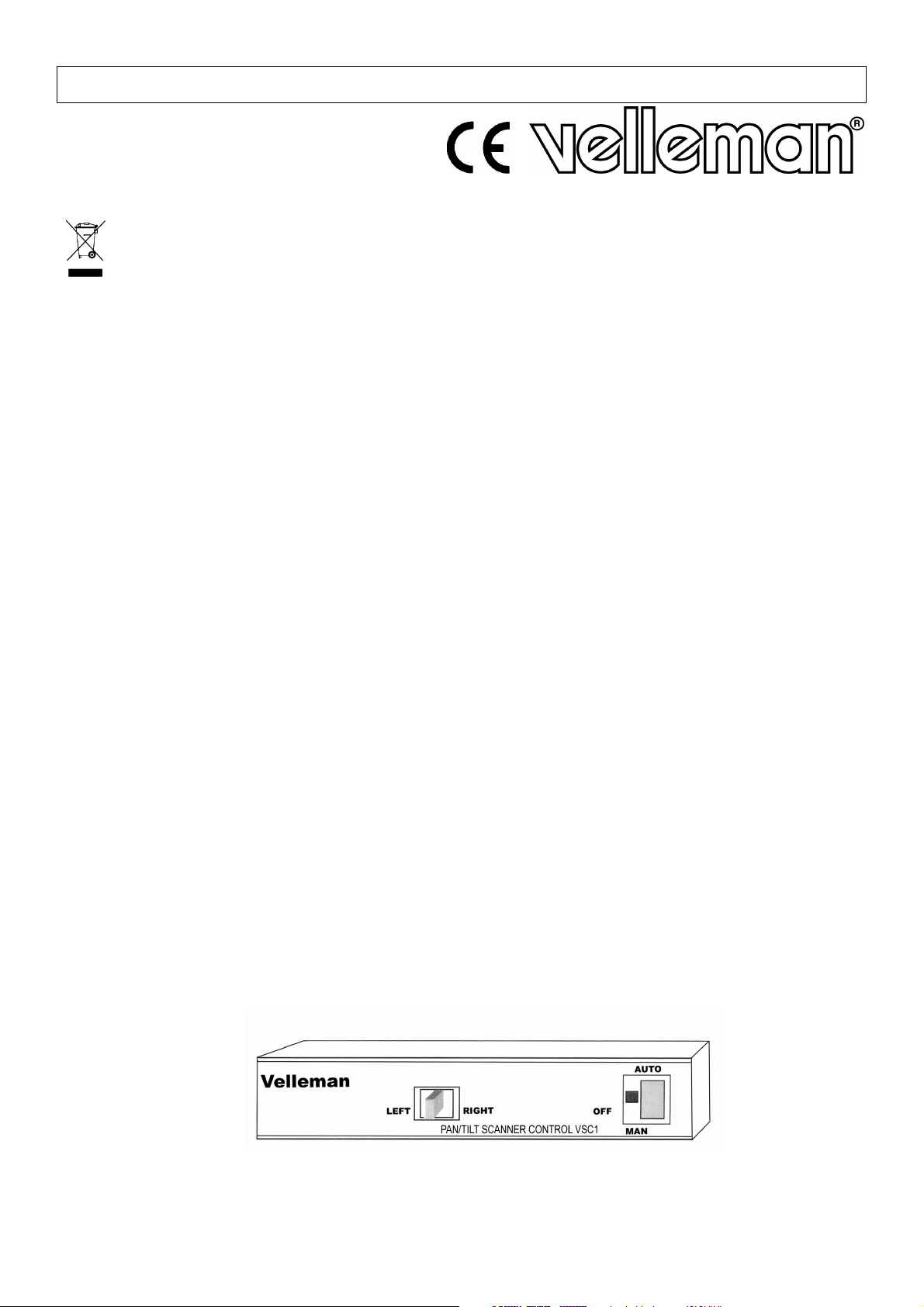
3. Controls
FRONT PANEL
1. Power : Place the rocker switch in the "AUTO"-position to make the green LED light up. The scanner will now
make all necessary left-right adjustments automatically. Put the rocker switch in the "MAN"-position to
make the red LED light up. The position of the scanner will now have to be adjusted manually. No
LEDs are lit if the device is OFF.
2. LEFT and RIGHT : paddle switch used to make the scanner turn to the left or right.
VSC1 VELLEMAN
Page 4

4
BACK PANEL
1. AC POWER : terminal 1
2. LEFT : terminal 2
3. RIGHT : terminal 3
4. COM : terminal 4
For more info concerning this product, please visit our website www.velleman.eu.
The information in this manual is subject to change without prior notice.
VSC1 – CONTROLEBOX VOOR SCANNER
1. Inleiding en kenmerken
Aan alle ingezetenen van de Europese Unie
Belangrijke milieu-informatie betreffende dit product
Dit symbool op het toestel of de verpakking geeft aan dat, als het na zijn levenscyclus wordt weggeworpen,
dit toestel schade kan toebrengen aan het milieu.
Gooi dit toestel (en eventuele batterijen) niet bij het gewone huishoudelijke afval; het moet bij een
gespecialiseerd bedrijf terechtkomen voor recyclage.
U moet dit toestel naar uw verdeler of naar een lokaal recyclagepunt brengen.
Respecteer de plaatselijke milieuwetgeving.
Hebt u vragen, contacteer dan de plaatselijke autoriteiten inzake verwijdering.
Dank u voor uw aankoop! Lees deze handleiding grondig voor u het toestel in gebruik neemt. Werd het toestel
beschadigd tijdens het transport, installeer het dan niet en raadpleeg uw dealer.
"AUTO"-bediening is geactiveerd : aangegeven door groene led
"MAN"-bediening is geactiveerd : aangegeven door rode led
Toestel is uitgeschakeld ("OFF") : geen enkele led brandt
Speciale schroefaansluiting met connector die kan worden losgekoppeld. Dit maakt de montage van het toestel zeer
eenvoudig.
2. Technische specificaties
Draairegeling "LEFT/RIGHT" paddle schakelaar
Voeding "MAN/AUTO/OFF" tuimelschakelaar
Ingangsspanning 220-230VAC
Uitgangsspanning naar scanner 24VAC
Werktemperatuur -5 tot +60°C
Connector Losschroefbare connector
Materiaal & Kleur Staal, gebroken wit
Afmetingen 212mm (D) x 218mm (B) x 45mm (H)
Gewicht 1.0kg
3. Regelingen (zie fig.)
FRONTPANEEL
1. Voeding : Plaats de tuimelschakelaar in de "AUTO"-stand om de groene led te doen branden. De positie van de
scanner wordt nu automatisch aangepast. Plaats de tuimelschakelaar in de "MAN"-stand om de rode
led te doen branden. De positie van de scanner moet nu manueel worden aangepast. Geen enkele
led brandt indien het toestel in de "OFF"-stand staat.
2. LEFT en RIGHT : paddle-schakelaar om de scanner naar links en rechts te doen draaien.
VSC1 VELLEMAN
Page 5

5
ACHTERPANEEL
1. AC VOEDING : aansluitklem 1
2. LEFT : aansluitklem 2
3. RIGHT : aansluitklem 3
4. COM : aansluitklem 4
Voor meer informatie omtrent dit product, zie www.velleman.eu.
De informatie in deze handleiding kan te allen tijde worden gewijzigd zonder voorafgaande kennisgeving.
VSC1 – BOÎTE DE CONTRÔLE POUR SCANNER
1. Introduction et caractéristiques
Aux résidents de l'Union européenne
Des informations environnementales importantes concernant ce produit
Ce symbole sur l'appareil ou l'emballage indique que l’élimination d’un appareil en fin de vie peut polluer
l'environnement.
Ne pas jeter un appareil électrique ou électronique (et des piles éventuelles) parmi les déchets municipaux
non sujets au tri sélectif ; une déchèterie traitera l’appareil en question.
Renvoyer les équipements usagés à votre fournisseur ou à un service de recyclage local.
Il convient de respecter la réglementation locale relative à la protection de l’environnement.
En cas de questions, contacter les autorités locales pour élimination.
Nous vous remercions de votre achat ! Lire la présente notice attentivement avant la mise en service de l’appareil. Si
l’appareil a été endommagé pendant le transport, ne pas l’installer et consulter votre revendeur.
Opération « AUTO » est activée : indiquée par la LED verte
Opération « MAN » est activée : indiquée par la LED rouge
Appareil OFF : aucune LED n'est allumée
Connexion à vis spéciale avec connecteur détachable, ce qui facilite l'installation de l'appareil.
2. Spécifications techniques
Ajustement de la position Interrupteur à bascule « LEFT/RIGHT » (gauche/droite)
Alimentation Interrupteur à bascule « MAN/AUTO/OFF »
Tension d'entrée 220-230VCA
Tension de sortie vers scanner 24VCA
Température de travail -5 à +60°C
Connecteur Connecteur peut être dévissé
Matériau & Couleur Acier, blanc cassé
Dimensions 212mm (P) x 218mm (La) x 45mm (H)
Poids 1.0kg
3. Réglages (voir ill.)
PANNEAU FRONTAL
1. Alimentation : Mettez l'interrupteur à bascule dans la position « AUTO » pour allumer la LED verte. La position
du scanner est réglée automatiquement. Mettez l'interrupteur dans la position « MAN » pour
allumer la LED rouge. La position du scanner doit être réglée manuellement. Aucune LED n'est
allumée si l'appareil est désactivé (« OFF »).
2. LEFT et RIGHT : Interrupteur à bascule pour faire tourner le scanner à gauche et à droite.
VSC1 VELLEMAN
Page 6

6
PANNEAU ARRIERE
1. ALIMENTATION CA : borne de connexion 1
2. LEFT (gauche) : borne de connexion 2
3. RIGHT (droite) : borne de connexion 3
4. COM : borne de connexion 4
Pour plus d’information concernant cet article, visitez notre site web www.velleman.eu.
Toutes les informations présentées dans cette notice peuvent être modifiées sans notification préalable.
VSC1 – CAJA DE CONTROL PARA ESCÁNER
1. Introducción & Características
A los ciudadanos de la Unión Europea
Importantes informaciones sobre el medio ambiente concerniente este producto
Este símbolo en este aparato o el embalaje indica que, si tira las muestras inservibles, podrían dañar el
medio ambiente.
No tire este aparato (ni las pilas eventuales) en la basura doméstica; debe ir a una empresa especializada
en reciclaje. Devuelva este aparato a su distribuidor o a la unidad de reciclaje local.
Respete las leyes locales en relación con el medio ambiente.
Si tiene dudas, contacte con las autoridades locales para residuos.
¡Gracias por haber comprado la VSC1! Lea cuidadosamente las instrucciones del manual antes de usarla. Si el
aparato ha sufrido algún daño en el transporte no lo instale y póngase en contacto con su distribuidor.
Función « AUTO » está activada : el LED verde está encendido
Función « MAN » está activada : el LED rojo está encendido
Aparato desactivado (OFF) : no está encendido ningún LED
Conexión de tornillos especial con conector desmontable, lo que facilita la instalación del aparato.
2. Especificaciones
Ajuste de la posición Interruptor de palanca « LEFT/RIGHT » (izquierda/derecha)
Alimentación Interruptor de palanca « MAN/AUTO/OFF »
Tensión de entrada 220-230VCA
Tensión de salida hacia el escáner 24VCA
Temperatura de funcionamiento de -5 a +60°C
Conector conector por tornillos desmontable
Material & Color de acero, color hueso
Dimensiones 212mm (P) x 218mm (An) x 45mm (Al)
Peso 1.0kg
3. Ajustes (véase fig.)
PANEL FRONTAL
1. Alimentación: Ponga el interruptor de palanca en la posición « AUTO » para iluminar el LED verde. La posición
del escáner se ajusta automáticamente. Ponga el interruptor de palanca en la posición « MAN »
para iluminar el LED rojo. La posición del escáner se ajusta manualmente. No está encendido
ningún LED si el aparato está desactivado (« OFF »).
2. LEFT y RIGHT: Interruptor de palanca para hacer girar el escáner hacia la izquierda y derecha
VSC1 VELLEMAN
Page 7

7
PANEL TRASERO
1. ALIMENTATION CA : borne de conexión 1
2. LEFT (izquierda) : borne de conexión 2
3. RIGHT (derecha) : borne de conexión 3
4. COM : borne de conexión 4
Para más información sobre este producto, visite nuestra página web www.velleman.eu.
Se pueden modificar las especificaciones y el contenido de este manual sin previo aviso.
VSC1 – PAN CONTROLLER
1. Einführung & Eigenschaften
An alle Einwohner der Europäischen Union
Wichtige Umweltinformationen über dieses Produkt
Dieses Symbol auf dem Produkt oder der Verpackung zeigt an, dass die Entsorgung dieses Produktes nach
seinem Lebenszyklus der Umwelt Schaden zufügen kann.
Entsorgen Sie die Einheit (oder verwendeten Batterien) nicht als unsortiertes Hausmüll; die Einheit oder
verwendeten Batterien müssen von einer spezialisierten Firma zwecks Recycling entsorgt werden.
Diese Einheit muss an den Händler oder ein örtliches Recycling-Unternehmen retourniert werden.
Respektieren Sie die örtlichen Umweltvorschriften.
Falls Zweifel bestehen, wenden Sie sich für Entsorgungsrichtlinien an Ihre örtliche Behörde.
Danke für den Kauf der VSC1! Lesen Sie Ihre Bedienungsanleitung sorgfältig durch. Überprüfen sie, ob
Transportschäden vorliegen. Sollte dies der Fall sein, verwenden Sie das Gerät nicht und wenden Sie sich an Ihren
Händler.
"AUTO"-Bedienung ist aktiviert : die grüne LED brennt
"MAN"- Bedienung ist aktiviert : die rote LED brennt
Gerät ist ausgeschaltet ("OFF") : es brennt keine LED
Der spezielle abnehmbare Schraubanschluss vereinfacht die Montage.
2. Technische Daten
Drehregelung "LEFT/RIGHT" Kipphebelschalter
Spannungsversorgung "MAN/AUTO/OFF" Wippenschalter
EiIngangsspannung 220-230VAC
Ausgangsspannung zu Scanner 24VAC
Arbeitstemperatur -5 bis +60°C
Anschluss Schraubanschluss, kann entfernt werden
Material & Farbe Stahl, in gebrochenem Weiß
Abmessungen 212mm (T) x 218mm (B) x 45mm (H)
Gewicht 1.0kg
3. Regelungen (Siehe Abb.)
FRONTPLATTE
1. Spannungsversorgung: Stellen Sie den Wippenschalter in die "AUTO"-Position um die grüne LED zu aktivieren.
Die Position des Scanners wird jetz automatisch angepasst. Stellen Sie den
Wippenschalter in die "MAN"-Position um die rote LED zu aktivieren. Die Position des
VSC1 VELLEMAN
Page 8

8
Scanners wird jetz manuell angepasst. Keine einzige LED brennt wenn das Gerät in der
"OFF"-Position steht.
2. LEFT und RIGHT: Verwenden Sie den Kipphebelschalter um der Scanner nach links und rechts drehen zu lassen.
RÜCKSEITE
1. AC SPANNUNGSVERSORGUNG: Anschluss 1
2. LEFT : Anschluss 2
3. RIGHT : Anschluss 3
4. COM : Anschluss 4
Für mehr Informationen zu diesem Produkt, siehe www.velleman.eu.
Alle Änderungen vorbehalten.
VSC1 VELLEMAN
 Loading...