

Page 1
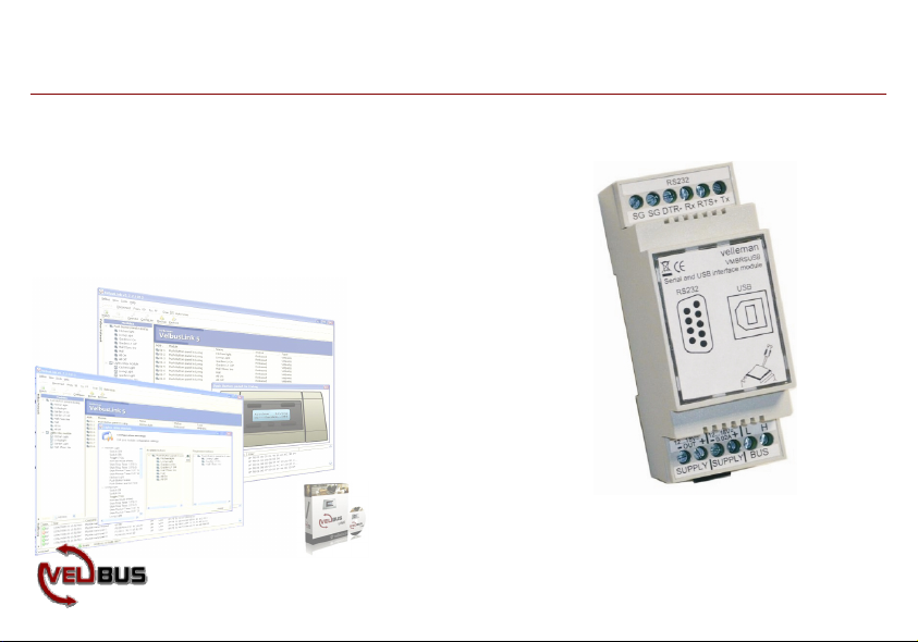
Serial & USB interface
Serial & USB interface
Serial & USB interface
can be used to control the VELBUS system through a computer
VELBUS message processing on the computer
galvanic separation between the computer and the VELBUS system
LED indication for the USB power supply
required power supply: 12 to 18 VDC
consumption: 15mA
power consumption USB port: 35 mA
VMBRSUSB
VMBRSUSB
VMBRSUSB
Page 2
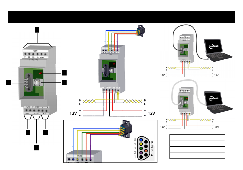
CONNECTION EXAMPLE - AANSLUITVOORBEELD - EXAMPLES DE CONNEXION - ANSCHLUSS-
BEISPIELE - EJEMPLO DE CONEXIÓN
1
USB
2
7
6
4
5
3
5 4 3 7 2
COM
RS232C :
Baud rate : 38400 Stop bits: 1
Data bits : 8 RTS: high
Parity : none DTR: low
Page 3
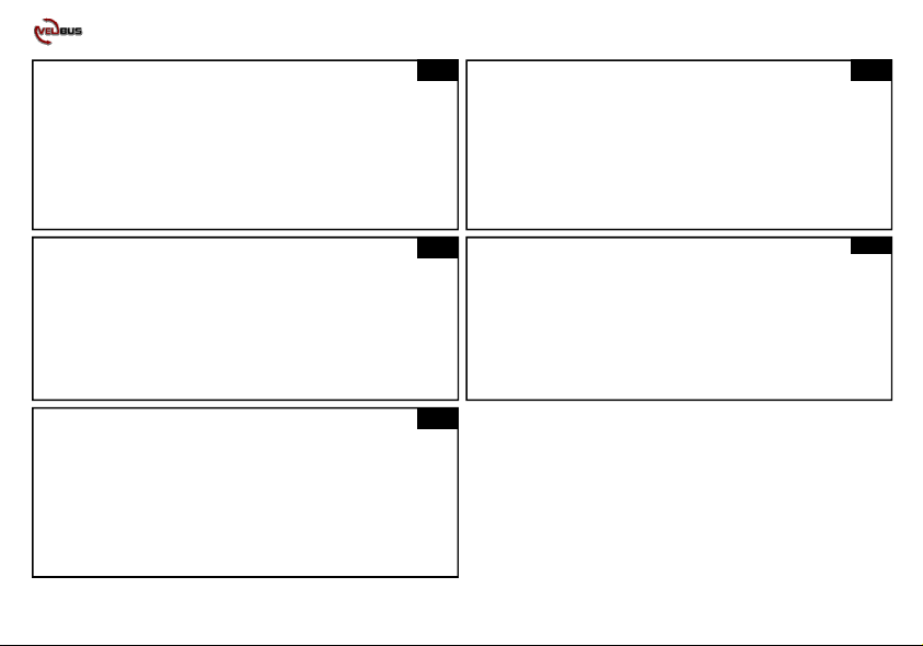
1. RS232 connection
2. Indication LED USB power
3. USB connection
4. VELBUS
5. 12V power input
6. 12V power output
7. RS232 connector
UK
1. RS232-Anschluss
2. Anzeige-LED für USB-Stromversorgung
3. USB-Anschluss
4. VELBUS
5. 12V Stromversorgung eingeschaltet
6. 12V Stromversorgung ausgeschaltet
7. RS232-Steckverbinder
D
1. RS232 aansluiting
2. USB voeding-indicatie LED
3. USB aansluiting
4. Velbus
5. 12V voeding ingang
6. 12V voeding uitgang
7. RS232 connector
1. Connexion RS232
2. Indication LED alimentation USB
3. Connexion USB
4. VELBUS
5. Entrée d’alimentation 12V
6. Sortie d’alimentation 12V
7. Connecteur RS232
NL
1. conexión RS232
2. indicador LED para la alimentación USB
3. conexión USB
4. VELBUS
5. alimentación 12V activada
6. alimentación 12V desactivada
7. Conector RS232
FR
ES
3
Page 4
COM
USB
RS232
Page 5

CONNECTION
CONNECTION
CONNECTION
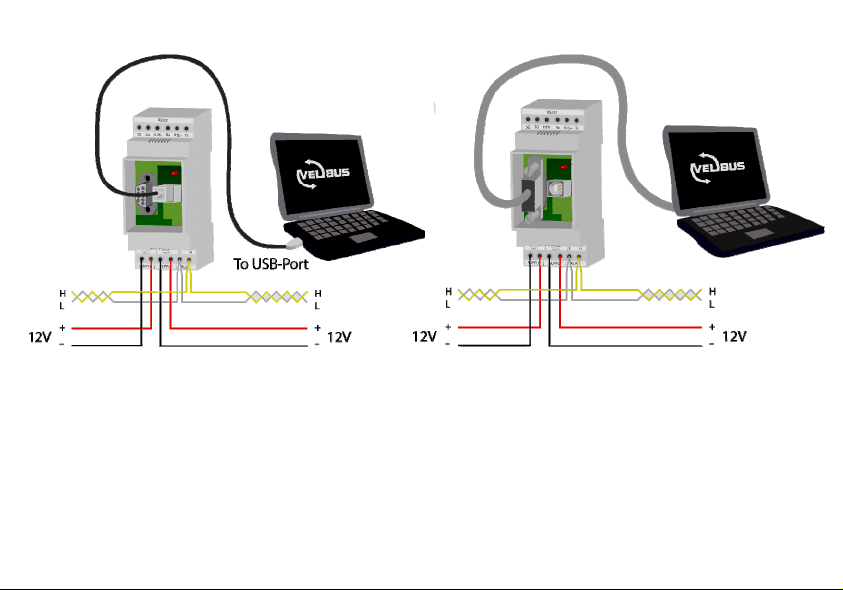
VELBUS connection
Connection of the modules is preferably done using twisted-pair
cables (EIB 2x2x0.8mm2, UTP 8x0.51mm - CAT5 or similar). Use
a twisted pair cable with 0.5mm² gauge or more when connecting
more than 10 modules or with long connections (more than 50m).
Connect the 12 ~ 18VDC (mind the polarity) to the module. Connect the bus (mind the polarity) with the module.
Connection through serial port
Connect the module to the COM port of the computer using a serial
cable (Velleman ref. CW014).
Remark: You can also install the serial connection elsewhere (e.g. on the side
of the fuse box). Use a 9-pole female SUBD-connector (Velleman ref. CC005)
Connection through USB port
Connect the module to a USB port of the computer. Use one of the
following Velleman USB cables: CW076, CW077, CW078,
CW090A, CW090B or CW090C.
Remark: The serial and USB connections are galvanically separated from the
VELBUS and the 12V power cable through an optical link. Only use one of
the possible connection methods: through the serial or through the USB port.
Never use both connection methods simultaneously.
AANSLUITING
AANSLUITING
AANSLUITING
Aansluiting van de velbus
Om de modules met elkaar te verbinden gebruikt men best een
twisted-pairkabel (EIB 2x2x0.8mm
gelijkwaardig). Indien er veel modules (meer dan 10) op de kabel
aangesloten zijn of bij zeer lange leidingen (langer dan 50m) is het
belangrijk om de draaddoorsnede voldoende dik te voorzien (0.5mm
of meer). Verbind de 12 tot 18V gelijkspanning (let op de polariteit)
met de module. Sluit de bus aan (let op de polariteit) op de module.
Via de seriële poort
Verbind de module met de COM-poort van de computer door
middel van een seriële kabel (Velleman art. CW014).
Opmerking: Het is mogelijk om de connector voor de seriële verbinding op een
andere plaats te voorzien (bv aan de zijkant van de zekeringkast). Gebruik
hiervoor een 9-polige vrouwelijke SUBD-connector (Velleman art. CC005).
Via de USB-poort
Verbind de module met een USB-poo rt van de computer. U kunt
hiervoor één van de volgende USB kabeltypes van Velleman gebruiken: CW076, CW077, CW078, CW090A, CW090B of CW090C
OPMERKING: De seriële en USB-computerverbinding zijn galvanisch
gescheiden van de VELBUS en de 12V voedingskabel via een optische link.
Gebruik slechts één van de mogelijke verbindingsmethoden, ofwel via de
seriële ofwel via de USB-poort, maar niet de beide tegelijk.
2
, UTP 8x0.51mm - CAT5 of
2
5
Page 6

CONNEXION
CONNEXION
CONNEXION
Connexion du système VELBUS
Interconnectez les modules en utilisant un câble torsadé (EIB
2x2x0.8mm
torsadé avec un diamètre de 0.5mm
2
, UTP 8x0.51mm - CAT5 ou similaire). Utilisez un câble
2
ou plus avec des connexions très
longues (> 50m) ou lors de la connexion de 10 modules ou plus.
Connectez le courant continu 12 ~ 18V (respectez la polarité) au
module. Connectez le bus (respectez la polarité) au module.
Connexion depuis le port sériel
Connectez le module au port COM de l’ordinateur à l’aide d’un
câble sériel (Velleman réf. CW014).
Remarque : Il est possible d’installer le connecteur sériel p.ex. sur le côté de la
boîte à fusibles. Utilisez un connecteur SUBD femelle à 9 broches (Velleman
réf. CC005).
Connexion depuis le port USB
Connectez le module au port USB de l’ordinateur à l’aide d’un des
câble USB Velleman : CW076, CW077, CW078, CW090A,
CW090B ou CW090C.
Remarque : Les connexions sérielle et USB sont galvaniquement séparées du
système VELBUS et du câble d’alimentation 12V via un lien optique. N’utilisez
qu’une des méthodes de connexion proposées (connexion sérielle ou USB). Ne
jamais utiliser les deux méthodes simultanément.
6
ANSCHLUSS
ANSCHLUSS
ANSCHLUSS
Das Velbus-System anschließen
Um die Module miteinander zu verbinden, verwenden Sie am besten
ein verdrilltes Kabel (EIB 2x2x0.8mm
gleichwertig). Wenn da viele Module (mehr als 10) mit dem Kabel
verbunden sind oder bei sehr langen Leitungen (über 50m) ist es wichtig, dass der Drahtdurchmesser ausreichend dick ist (0.5mm
mehr). Verbinden Sie die 12 bis 18V Gleichspannung mit dem Modul
(achten Sie auf die Polarität). Schließen Sie den Bus an das Modul an
(achten Sie auf die Polarität).
Über seriellen Anschluss
Verbinden Sie das Modul des Computers über ein serielles Kabel mit
dem COM-Anschluss (Velleman Bestell-Nr. CW014).
Bemerkung: Es ist möglich, um den Anschluss für die Serienschaltung anderswo
zu installieren (z.B. an der Seite des Sicherungskastens). Verwenden Sie dazu
eine 9-polige SUBD-Buchse (Velleman Bestell-Nr. CC005).
Über USB-Anschluss
Verbinden Sie das Modul mit einem USB-Anschluss des Computers.
Sie kann hierfür eines der folgenden USB-Kabel von Velleman verwenden: CW076, CW077, CW078, CW090A, CW090B oder CW090C.
Bemerkung: Die Serien- und USB-Computerverbindung sind galvanisch vom
VELBUS und dem 12V-Stromversorgungskabel über einen optischen link
getrennt. Verwenden Sie nur eine der möglichen Verbindungsmethoden, entweder über den Serienanschluss, oder über den USB-Anschluss, aber nicht die
beiden gleichzeitig.
2
, UTP 8x0.51mm - CAT5 oder
2
oder
Page 7

CONEXIÓN
CONEXIÓN
CONEXIÓN
Conexión del velbus
Para conectar los módulos utilice un cable de par trenzado (EIB
2x2x0.8mm2, UTP 8x0.51mm - CAT5 o equivalente). Si están
conectados muchos módulos (más de 10) al cable o en caso de
conexiones muy largas (más de 50m), es importante que el diámetro del cable sea demasiado grueso (0.5mm2 o más).
Conecte la corriente continua de 12 a 18V al módulo (respete la
polaridad). Conecte el bus al módulo (respete la polaridad).
Por conexión serie
Conecte el módulo con un cable serie al puerto COM del ordenador (Velleman art. Nr. CW014).
Nota: Es posible instalar el conector en serie p.ej. el lateral de la caja de
fusibles. Utilice un conector SUBD hembra de 9 polos (Velleman ref. CC005)
Por puerto USB
Conecte el módulo a un puerto USB del ordenador. Es posible
utilizar unos de los siguientes cables USB de Velleman: CW076,
CW077, CW078, CW090A, CW090B o CW090C.
Nota: La conexión serie y la conexión USB del ordenador están galvánicamente separadas del VELBUS y del cable de alimentación 12V por una
conexión óptica. Utilice sólo uno de los métodos de conexión propuestos
(conexión serie o conexión USB). No utilice ambos métodos al mismo
tiempo.
7
Page 8

Page 9

USE
USE
USE
Run a computer program allowing you to communicate with the
VELBUS system. Download this program, the tutorial or all
needed information to write a custom program through our http://
www.velbus.be/consumers/downloads/. Connect the module to the
VELBUS system and the computer (see Connection).
First install the driver when first connecting the module to a computer through a USB port. The computer’s operating system will
detect the new hardware and will ask to localise and to install the
driver (.inf file) (c:\Progra m Files\Velleman\VelbusLink\Driver).
Once the driver correctly installed, you can use the Velbuslink
program. When powering the module, a “Bus active” and
“Reception ready” message will be sent to the computer.
All messages appearing on the VELBUS system will also be sent
serially to the computer. Valid commands generated by the computer will be sent to the module via the serial or USB port.
These commands are placed on the VELBUS system through the
interface module. When an excessive amount of commands has
been sent in one time, the reception buffer will be filled. This will
be reported to the computer. The computer program must interrupt
the forwarding and wait for a “Reception ready” message to be
able to offer new commands.
If the commands can not be placed correctly on the VELBUS, a
bus error will occur and will be forwarded to the computer. The
interface module will auto-restart after 25 seconds and erase the
reception buffer.
GEBRUIK
GEBRUIK
GEBRUIK
Op de computer moet men een programma draaien dat toelaat met het
VELBUS-systeem te communiceren. Dit programma, de handleiding
(tutorial) of informatie om zelf een programma te ontwikkelen kan men
downloaden van de website (http://www.velbus.be/consumers/
downloads/). Verbind de module met het VELBUS-systeem en de
computer (zie aansluiting).
Wanneer de module voor de eerste maal met een computer verbonden
wordt via de USB-poort moet de driver nog geinstalleerd worden. Het
besturingssysteem van de computer detecteert nieuwe hardware en
vraagt om de driver (.inf bestand) te lokaliseren en te installeren
(c:\Program Files\Velleman\VelbusLink\Driver). Eenmaal de driver
correct geïnstalleerd is kan het Velbuslink programma gebruikt worden.
Bij het onder spanning komen van de module wordt een ‘Bus actief’ en
‘Ontvangst klaar’ boodschap naar de computer verstuurd.
Alle boodschappen die nu op het VELBUS-systeem verschijnen,
worden eveneens verstuurd naar de computer. Geldige commando’s
gegenereerd door de computer worden via de seriele of USB-poort naar
de module verstuurd. Deze commando’s worden door de interface
module op het VELBUS-systeem geplaatst. Indien er teveel commando’s ineens verstuurd worden, zal de ontvangstbuffer vol lopen en
wordt dit gemeld aan de computer. Het computerprogramma moet nu
het verze nden onderbreken en wachten op een ‘ontvangst klaar’ bericht
om terug nieuwe commando’s te kunnen aanbieden.
Als de commando’s niet correct op de VELBUS geplaatst kunnen
worden, zal er een busfout optreden en doorgegeven worden naar de
computer. Na 25 seconden zal de interface module zichzelf herstarten
en de ontvangstbuffer wissen.
9
Page 10

EMPLOI
EMPLOI
EMPLOI
Lancez un logiciel permettant la communication avec le système
VELBUS. Ce logiciel, le mode d’emploi ou toute information nécessaire au développement du logiciel peuvent être téléchargés à partir du
lien http://www.velbus.be/consumers/downloads/
module au système VELBUS et l’ordinateur (voir Connexion).
Lors de la première connexion du module au port USB de l’ordinateur,
le pilote devra encore être installé. Le système d’exploitation de
l’ordinateur détecte un nouveau périphérique et demande à localiser et
à installer le pilote (le fichier .inf) (c:\Program Files\Ve lleman\Velb usLink \Driver). Une fois le pilote correctement
installé, le logiciel Velbuslink pourra être lancé. Lors de la mise sous
tension du module, des messages "Bus actif" et "Prêt pour la réception" sont envoyés vers l’ordinateur.
Tous les messages apparaissant sur le système VELBUS seront également envoyés vers l’ordinateur. Les commandes valides générée s par
l’ordinateur seront envoyées vers le module depuis le port sériel ou
USB. Ces commandes sont placées sur le système VELBUS par
l’interface. Lors d’un surplus de commandes envoyées, le tampon de
réception sera saturé. Cette saturation sera notifiée à l’ordinateur. Le
programme interrompt le transfert et attend le message "Prêt pour la
réception" avant de pouvoir présenter de nouvelles commandes.
Lorsque les commandes ne sont pas correctement placées sur le
VELBUS, une erreur bus apparaîtra et celle-ci sera envoyée à l’ordinateur. L’interface se rétablira et effacera le tampon de réception.
. Connectez le
10
ANWENDUNG
ANWENDUNG
ANWENDUNG
Auf dem Computer soll man ein Programm, das mit de m VELBUS System kommunizieren kann, ablaufen lassen. Dieses Programm, die
anleit ung (tutorial) oder Information, um selber e in Progra mm zu entwickeln können Sie von unserer Website (http://www.velbus.be/
consumers/downloads/) herunterladen. Verbinden Sie das Modul mit
dem VELBUS-System und dem Computer (siehe Anschluss).
Wenn das Modul zum ersten Mal über den USB-Anschluss mit einem
Computer verbunden wird, muss der Treiber noch installiert werden.
Das Betriebssystem des Computers detektiert die neue Hardware und
bittet darum, den Treiber (.inf Datei) zu lokalisieren und installieren
(c:\Program Files\Velleman\VelbusLink\Driver). Wenn der Treiber
korrekt installiert ist, kann das Velbuslink-Programm verwendet werden.
Beim Einschalte n des Moduls wird eine ‘Bus aktiv’ und ‘Emp fang
fertig’-Meldung an den Computer geschickt.
Alle Nachrichten, die jetzt auf dem VELBUS-System erscheinen, werden auch an den Computer geschickt. Gültige Befehle, die vom Computer über den Serien- oder USB-Anschluss generiert werden, werden an
das Modul geschickt. Diese Befehle werden durch eine serielle Schnittstelle auf das VELBUS-System übertragen. Wenn zuviele Befehle zur
gleichen Zeit verschickt werden, wird der Empfangsspeicher voll geraten und wird das an den Computer gemeldet. Das Computer-programm
muss jetzt dass Versenden unterbrechen und auf eine ‘Empfang fertig’Meldung warten, um neue Befehle anbieten zu können. Wenn die Befehle nicht korrekt an das VELBUS-System übertragen werden können,
wird ein Busfehler auftreten und wird er an den Computer weitergeleitet
werden. Nach 25 Sekunden wird sich das serielle Schnittstellenmodul
neu starten und den Empfangspuffer löschen.
Page 11

USO
USO
USO
Ejecute un software en el ordenador que permite comunicar con el
sistema VELBUS. Descargue este programa, el manual del usuario (tutorial) o unas informaciones para desarrollar su propio
programa (http://www.velbus.be/consumers/downloads/
el módulo al sistema VELBUS y al ordenador (véase Conexión).
Al conectar el módulo por primera vez a un ordenador por el
puerto USB es necesario todavía instalar el driver. El sistema
operativo del ordenador detecta nuevo hardware y pide que localice e instale (c:\Program Files \Velleman\VelbusLink\Driver) el
driver (fichero .inf). Después de haber instalado el driver correctamente, es posible utilizar el programa Velbuslink. Al activar el
módulo se envía el mensaje ‘Bus activo’ y ‘Listo para la recepción’
al ordenador. Cada mensaje que aparece ahora en el sistema VELBUS se enviará también al ordenador. Los mandos válidos generados por el ordenador se enviarán al módulo por el puerto serie o el
puerto USB.
Los mandos se ponen en el sistema VELBUS por el módulo interface. Si se envía demasiados mandos a la vez, el tampón receptor
se llenará. Esto se comunicará al ordenador. El software interrumpirá el envío y esperará hasta que reciba el mensaje ‘Recepción
terminada’ antes de poder ofrecer nuevos mandos. Si no es posible
poner los mandos en el VELBUS de manera correcta, une error de
bus aparecerá y se transmitirá al ordenador. Después de 25 segundos, el módulo de interface serie se reactivará y borrará el tampón
receptor
). Conecte
11
Page 12

VELLEMAN NV
Legen Heirweg 33
9890 Gavere
Belgium - Europe
www.velbus.be
www.velbus.be
www.velbus.be
Modifications and typographical errors reserved - © Velleman nv - HVMBRSUSB - REV.1 - 2012
5 410329 347093
 Loading...