

Page 1
I
M
D
B
M
V
V
V
M
M
B
B
D
D
M
M
I
I
Dimmer for
resistive and inductive loads
Page 2

CONTENTS
CONTENTS ............................................................................................................................... 2
DESCRIPTION ........................................................................................................................... 3
PROPERTIES ............................................................................................................................ 3
VELBUS CHARACTERISTICS ................................................................................................. 5
OVERVIEW ................................................................................................................................ 6
LED INDICATIONS .................................................................................................................... 7
LOCAL OPERATION ................................................................................................................ 8
USE ............................................................................................................................................ 9
Connection scheme with mains voltage lamps ....................................................................... 9
Connection scheme with low voltage lamps ......................................................................... 10
Terminator ............................................................................................................................ 11
Configuration ........................................................................................................................ 12
Address: ............................................................................................................................ 12
Dimmer mode: .................................................................................................................. 12
Control functions: .............................................................................................................. 12
PROBLEM SOLVING .............................................................................................................. 16
Communication error ............................................................................................................ 16
Non-dimmable load .............................................................................................................. 16
Temperature alarm ............................................................................................................... 16
Temperature protection ........................................................................................................ 17
No fault indication but lamp does not light up ....................................................................... 17
The lamp remains on ............................................................................................................ 17
VERIFY SOFTWARE VERSION .............................................................................................. 18
2 VMBDMI Dimmer manual – edition 1
Page 3

DESCRIPTION
With this module it is possible to dim lamps operating on mains voltage. Also suitable for dimming low voltage
lamps in combination with a wire-wound iron core transformer.
PROPERTIES
Use:
Required mains voltage: 220...240V/50Hz
Suitable to control incandescence or halogen lamps on mains voltage
Suitable to control low voltage halogen lamps in combination with a dimmable wire-wound iron core
transformer
Suitable for some types of dimmable LED lamps on mains voltage
Output:
Maximum load: 400W @ 230V/50Hz
Leading edge phase control
Slowly switching on and off (ca. 1.5s) will prolong the life span of the lamp
Dimming from 0 to 100% in ca. 4 seconds
Power grid distortion (EMI) conform EN55015
Protection:
Built-in non-resettable: 4A slow
Verification of too inductive loads (holding current triac). This protection can be disabled for some types of
lamps e.g. dimmable lamps
Thermal protection:
o When temperature reaches 80°C, light output is reduced to 25% of the desired value
o When temperature reaches 90°C, the lamp is switched off
o Thermal protection is switched off when temperature drops below 60°C
o Tolerance on thermal protection: ±4°C
LED indications:
Status of the dimmer:
o Continuous on: desired dimming value reached
o Slow flash: timer running
o Fast flash: dimming value changing
o Two short flashes: communication error detected
o Three short flashes: not possible to dim load with this dimmer
o Four short flashes: temperature alarm (light output reset to 25% of desired value)
o Five short flashes: thermal protection (lamp is switched off)
Presence of input voltage
Sending and receiving Velbus data
Report status to control modules
Module power:
Required input voltage: 12...18Vdc
Consumption in stand-by: 28mA@18Vdc
Maximum consumption: 30mA@18Vdc
Dimensions:
Standard DIN-rail housing: 2 modules wide
Length x width x height: 90 x 36 x 58mm
Configuration:
Only configurable via Velbus PC interface (VMB1USB, VMB1RS or VMBRSUSB) and the VelbusLink
software
Software addressing (up to 250 possible addresses)
Storage capacity for 37 different pushbuttons and their function
Multiple functions and time settings can be set via software
Learned pushbuttons are maintained during power outage
VMBDMI Dimmer manual – edition 1 3
Page 4

Operation:
Local operation on the module (on/off when short push, dimming when push and hold)
Via Velbus commands or pushbuttons connected to the Velbus system
Various operation functions:
o Momentary
o Off or slowly off
o On or slowly on
o On/off or slowly on.off
o Timer (start/stop, resettable or non-resettable
o Dim (more or less light output)
o More light output
o Less light output
o Evoke atmospheres
o Multiple step dimmer
o Forced off
o Forced on
o Suppress
Time settings:
Only settable via the VelbusLink software
Switch-off time adjustable between:
o 1 sec ... 2 min, increment 1 sec
o 2 min ... 5 min, increment 15 sec
o 5 min ... 30 min, increment van 30 sec
o 30 min ... 1 hour, increment 1 min
o 1 hour ... 5 hours, increment 15 min
o 5 hours ... 10 hours, increment 30 min
o 10 hours ... 24 hours, increment 1 hour
o 2 days
o 3 days
o No switch-off time
Dimming speed adjustable between:
o 2 sec ... 2 min, increment 1 sec
o 2 min ... 5 min, increment 15 sec
o 5 min ... 30 min, increment 30 sec
o 30 min ... 1 hour, increment 1 min
o 1 hour ... 5 hours, increment 15 min
o 5 hours ... 10 hours, increment 30 min
o 10 hours ... 23 hours, increment 1 hour
4 VMBDMI Dimmer manual – edition 1
Page 5

VELBUS CHARACTERISTICS
2-wire communication for Velbus data + 2 wires for power supply
Data transmission rate: 16.6 Kbit/s
Serial data protocol: CAN (Controller Area Network)
Short circuit protected (both towards ‘+’ and ‘-‘ of the power supply)
Bus error indication: 2 short flashes of the indicator LEDs
Self repairing after 25 seconds when a bus fault occurs
Each dimmer can be given a name of up to 16 characters (max.).
The dimmer module can send following messages:
Dimmer status
Module type: dimmer module (including software version)
dimmer name
Communication fault counter
Memory content
The dimmer module can send following commands:
Turn off LEDs on a control module
Turn on LEDs on a control module
Make LEDs flash slowly or fast on a control module
The dimmer module can receive following commands:
The status of a pushbutton module
The status of a slider button
The dimmer module can receive following commands:
Set dimmer value
Return to last used dimming value
Stop dimming
Start timer
Forced off
Cancel forced off
Forced on
Cancel forced on
Suppress
Cancel suppress
Request dimmer status
Request type of module and software version
Request communication fault counter
Request dimmer name
Request memory content
Overwrite memory content
Clear pushbutton indication LED
VMBDMI Dimmer manual – edition 1 5
Page 6
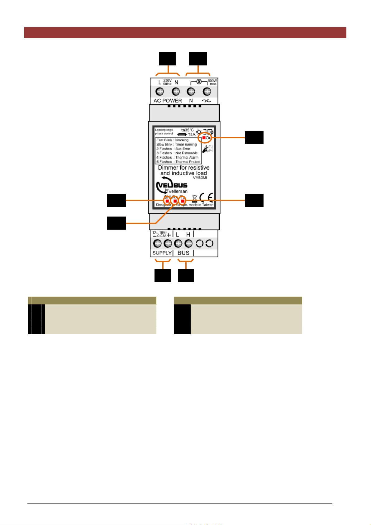
OVERVIEW
1
2
8
5 7
6
3 4
Connections
mains voltage
1
Load
2
Velbus power supply
3
Velbus
4
Power supply
5
Receiving Velbus data
6
Sending Velbus data
7
Output status
8
LED indications
6 VMBDMI Dimmer manual – edition 1
Page 7

LED INDICATIONS
ON-LED: On when
power supply is present
Output LED:
Off: load (lamp) is off
On: desired dimming value is reached
Fast flash: dimming value changes
Slow flash: switch-off delay is running
Two short flashes: communication error
Three short flashes: non-dimmable load
Four short flashes: temperature alarm
Five short flashes: thermal protection
Rx-LED: On when
receiving Velbusdata
Tx-LED: On when sending Velbusdata
VMBDMI Dimmer manual – edition 1 7
Page 8

LOCAL OPERATION
Remove top cover.
Local operation:
Short push: on/off
Long push: dim
8 VMBDMI Dimmer manual – edition 1
Page 9

USE
This module can be used to dim dimmable mains voltage lamps or low voltage lamps in combination with a
dimmable iron core transformer.
The module is added to the Velbus system and controlled via the control panel VMB4PD or via pushbuttons
connected to a pushbutton interface VMB8PB.
To connect the Velbus modules with each other, a twisted pair cable is recommended (EIB 2x2x0.8mm², UTP
4x2x0.51mm² - CAT5 or equivalent).
When a lot of modules (more than 10) are connected on the Velbus cable or the Velbus cable is very long (over
50m) it is important to foresee a cable with sufficient wire diameter (0.5mm
2
of more).
Connect the bus to the module (mind the polarity).
Connection scheme with mains voltage lamps
Attention:
At higher output power the dimmer housing becomes hot. It is strongly recommended to keep sufficient free space
around the dimmer to allow adequate ventilation.
VMBDMI Dimmer manual – edition 1 9
Page 10

Connection scheme with low voltage lamps
Use a dimmable iron core transformer or an electronic transformer that can be dimmed using leading edge phase
control.
Attention:
At higher output power the dimmer housing becomes hot. It is strongly recommended to keep sufficient free space
around the dimmer to allow adequate ventilation.
10 VMBDMI Dimmer manual – edition 1
Page 11

Terminator
Remove top cover.
Terminat
In normal circumstances only 2 ‘TERM’ terminators must be foreseen in a complete Velbus installation. Usually
this will be on one module inside the distribution box and on the module the furthest from the distribution box.
In all other cases it must be removed.
Remark:
In a wiring scheme with a lot of branches a terminator is placed on a module inside the distribution box and on the
control panel furthest from the distribution box. Should communication problems occur, an additional terminator
can be placed on another branch. However, the number of terminators should be kept to a minimum as additional
terminators place a heavy load on the bus.
VMBDMI Dimmer manual – edition 1 11
Page 12

Configuration
This dimmer module can only be configured using the VelbusLink software.
The address, dimmer mode and control functions can be configured.
Address:
Every module in the Velbus system must have a unique address.
Address setting is done by software.
Dimmer mode:
The dimmer defaults to inductive loads. It will switch off when the load is to inductive. When using dimmable LED
lamps it is recommended to disable this protection by setting the dimmer mode to resistive loads.
Control functions:
The dimmer module is controlled via pushbuttons connected to the Velbus system using a pushbutton interface or
control panel.
Up to 37 different pushbuttons can be assigned. Every pushbutton can activate a different function.
Function Description
1 Momentary
2 Off
3 Off with timer lock
4 Off with timer lock after short
push
5 Off with timer lock after long
push
6 Slowly off
7 On
8 On with timer lock
9 On with timer lock after short
push
10 On with timer lock after long
push
11 Slowly on
Light remains on as long as switch is closed
Light is switched off. To create an ‘all off’ function, on every dimmer the
same pushbutton is assigned the ‘off’ function.
The light is switched off; the timers can not be started.
A short push on the pushbutton switches off the light; the timers can
not be started. A long push will switch off the lights; all timer functions
remain available.
A short push on the pushbutton switches off the light; all timer functions
remain available. A long push will switch off the lights; the timers can
not be started.
The light slowly dims during the specified time duration.
The light is switched on.
The light is switched on; the timers can not be started.
A short push on the pushbutton switches on the light; the timers can
not be started. A long push will switch on the lights; all timer functions
remain available.
A short push on the pushbutton switches on the light; all timer functions
remain available . A long push will switch on the lights; the timers can
not be started.
The light slowly turns brighter during the specified time.
12 On/off
13 On/off with timer lock
14 On/off with timer lock after
short push
15 On/off with timer lock after long
push
16 Slowly on/off
17 Start/stop timer
Every push reverses the condition of the light.
Every push reverses the condition of the light (on/off).
When the light is on, timers can not be started.
Every push reverses the condition of the light. Only when the light was
switched on via a short push the timers can not be started.
Every push reverses the condition of the light. Only when the light was
switched on via a long push the timers can not be started.
Every push will slowly switch the light on or off during the specified
time durations.
A push will switch on the light during a specified time.
Another push while the light is on switches the light off immediately.
12 VMBDMI Dimmer manual – edition 1
Page 13

18 Start/stop timer with slow
on/off
A push will slowly switch on the light. After expiration of the switch-off
time, the light slowly turns off. Another push will the light is on will
slowly switch off the light.
19 Resettable timer
20 Resettable timer with slow
on/off
21 Non-resettable timer
22 Non-resettable timer with slow
on/off
23 Slow on when closing and slow
off when opening switch
24 Dim on
25 On when short push,
dim on when long push
26 Previous dimming value when
short push
Dim on when long push
A push will switch on the light during a preset time. Another push while
the light is on will restart the timer.
A push will slowly switch on the light. After expiration of the switch-off
time, the light slowly turns off. Another push while the light is on will
restart the light timer.
A push will switch on the light during a preset time.
Another push while the light is on will have no effect.
A push will slowly switch on the light. After expiration of the switch-off
time, the light slowly turns off.. Another push while the light is on will
have no effect.
When closing the switch the light will slowly turn on; when opening the
switch it will slowly turn off. If the switch-off timer expired an the switch
is still closed, the light will slowly turn off.
A push will make the light turn brighter. After expiration of the switch-off
timer, the light switches off.
A short push will switch on the light at full brightness.
A long push will turn the light on brighter. Releasing the button will
leave the light on the reached light output. After expiration of the
switch-off timer, the light switches off.
A short push will turn on the light to the last brightness setting.
When push and hold, the light will turn brighter, releasing the button
will leave the light at the reached light output. After expiration of the
switch-off timer, the light switches off.
27 Dim off
28 Off when short push
Dim off when long push
29 Dimming
30 On/Off when short push
Dim off when long push
31 Previous dim value when short
push
Dim when long push
32 Select dimming atmosphere
A push will dim the light. Releasing the button will leave the light at the
reached light output. After expiration of the switch-off timer, the light
switches off.
A short push will turn the light off.
When push and hold, the light will dim, releasing the button will leave
the light at the reached light output. After expiration of the switch-off
timer, the light switches off.
Pushing the button will make the light shine weaker or brighter.
Releasing the button will leave the light at the reached light output.
Another push will reverse dimming direction.
After expiration of the switch-off timer, the light switches off.
A short push will turn the light on (full brightness) when it was initially
off; or switches off when it was on. When push and hold, the light will
dim up or down, releasing the button will leave the light at the reached
light output. Another push will reverse dimming direction. After
expiration of the switch-off timer, the light switches off.
A short push will turn on the light to the last brightness setting when the
light was off, or switches off when it was on.
When push and hold, the light will dim up or down, releasing the button
will leave the light at the reached light output. Another push will reverse
dimming direction. After expiration of the switch-off timer, the light
switches off.
A push will select a preferred lighting brightness. The time required to
reach this setting and the switch-off time can be configured.
33 Dimming with slider
VMBDMI Dimmer manual – edition 1 13
The position of the slider determines the output brightness.
Page 14

34 Multiple position dimmer
A push will select the next preferred lighting brightness from a table.
The time required to reach this setting and the switch-off time can be
configured. Up to 14 preferred lighting brightness’s can be stored in the
table. Factory defaults are: 25, 50, 75, 100, 75, 50 en 25%.
35 Forced off when switch closed
36 Forced off when switch open
37 Forced off
38 Enable or disable forced off
mode
39 End forced off
40 Forced on when switch closed
41 Forced on when switch open
42 Forced on
As long as the switch is closed, the light can not be switched on.
As long as the switch is open, the light can not be switched on.
A push will prevent the light from being switched on during a specified
time period.
A push will prevent the light from being switched on during a specified
time period. Another push will end forced off mode.
Forced off mode is ended when pushing such a button.
Remark:
The forced off status can still be determined by the forced off when
switch open or closed.
As long as the switch is closed the light is switched on and all other
operations are ignored.
Remark:
Forced off has precedence over forced on.
As long as the switch is open the light is switched on and all other
operations are ignored.
Remark:
Forced off has precedence over forced on.
A push will turn on the light and all other operations are ignored during
the preset time.
Remark:
Forced off has precedence over forced on
43 Switching on or off in forced-on
mode
44 Cancel forced-on
45 Cancel when switch closed
46 Cancel when switch open
47 Suppress
48 Activate/deactivate suppress
mode
49 Cancel suppress
A push will turn on the light and all other operations are ignored during
the preset time. Another push will cancel forced-on mode.
Remark:
Forced off has precedence over forced on
A push will cancel forced-on mode
Remark:
The forced-on condition can still be determined by the forced on when
switch open/close function.
As long as the switch is closed the light is off but the internal functions
remain active. When the switch is opened, the internal condition is
forwarded to the lamp.
As long as the switch is open the light is off but the internal functions
remain active. When the switch is closed, the internal condition is
forwarded to the lamp
A push will switch off the light during a preset time, but the internal
functions remain active.
A push will switch off the light during a preset time, but the internal
functions remain active. Another push will deactivate suppress mode.
A push will forward the internal condition to the relay.
14 VMBDMI Dimmer manual – edition 1
Page 15

For some functions, a switch-off time can be set between:
o 1 sec and 2 min, increment 1 sec
o 2 min and 5 min, increment 15 sec
o 5 min and 30 min, increment 30 sec
o 30 min and 1 hour, increment 1 min
o 1 hour and 5 hours, increment 15 min
o 5 hours and 10 hours, increment 30 min
o 10 hours and 24 hours, increment 1 hour
o 2 days
o 3 days
o No switch-off time
And a dimming speed can be set:
o 2 sec to 2 min, increment 1 sec
o 2 min to 5 min, increment 15 sec
o 5 min to 30 min, increment 30 sec
o 30 min to 1 hour, increment 1 min
o 1 hour to 5 hours, increment 15 min
o 5 hours to 10 hours, increment 30 min
o 10 hours to 23 hours, increment 1 hour
VMBDMI Dimmer manual – edition 1 15
Page 16

PROBLEM SOLVING
The dimmer has an indication LED. This LED indicates a fault condition by a number of light flashes.
Output LED
Two short flashes: communication
error
Three short flashes: non-dimmable
load
Four short flashes: temperature
alarm
Five short flashes: thermal
protection
Communication error
The LED flashes 2 times briefly.
Check the bus-wiring for interruptions and reversing of the ‘L’ and ‘H’ terminals.
Check the number of terminators (TERM) in the installation. Too many or not enough can cause problems.
Switch off the Velbus power supply and measure the resistance between the ‘L’ and ‘H’ terminals of the bus.
A value less than 50Ω means too many terminators, more than 250Ω means no terminators present.
At least two modules must be connected to the bus.
Non-dimmable load
The LED flashes 3 times briefly.
The dimmer protects itself from to inductive loads e.g. like in the case of a transformer without a lamp connected.
This error will disappear automatically when a lamp is connected to the transformer and the dimmer is operated
again.
For some loads e.g. dimmable LD lamps it is better to disable this control via the configuration software
(Velbuslink). Set the dimmer for resistive loads.
Temperature alarm
The LED flashes 4 times briefly.
The dimmer has a temperature sensor built-in. When the internal temperature is too high (>80°C) the dimmer will
auto-protect itself by reducing the dimming value to 25% of the desired value. When the temperature drops below
60°C the fault will reset itself automatically.
Check following points:
Connected power too high
Not enough free space around the dimmer (leave at least 1 module free)
Temperature inside distribution box too high (provide ventilation inside distribution box)
16 VMBDMI Dimmer manual – edition 1
Page 17

Temperature protection
The LED flashes 5 times briefly.
When the internal temperature is higher than 90°C the dimmer will switch itself off. Temperature has to drop
below 60°C to become operational again.
Check following points:
Connected power too high
Not enough free space around the dimmer (leave at least 1 module free)
Temperature inside distribution box too high (provide ventilation inside distribution box)
No fault indication but lamp does not light up
The lamp is broken or has poor contact with the fitting.
The circuit breaker or residual current device (RCD) were activated. First find out what caused this action and
solve the problem before reinstating the circuit breaker or RCD.
The fuse inside the dimmer has melted. This sometimes happens when the lamp breaks.
Remove the top cover.
Fuse 4A Slow
Use a screwdriver and slightly push the cap of the fuse holder down before unscrewing the fuse holder
anticlockwise. Use a pair of long nose pliers to lift the cap. Replace the fuse and screw the cap back in place.
The lamp remains on
A lamp break down might lead to a short current peak. This peak might damage the triac causing it to keep
conducting.
In this case the module will have to be shipped back to the manufacturer for repair.
VMBDMI Dimmer manual – edition 1 17
Page 18

VERIFY SOFTWARE VERSION
The software version can be retrieved via the Velbuslink software.
Via the link http://www.velbus.eu
available, download and install it. Connect the Velbus interface to a PC, run the upgrade-software and follow the
instructions on the screen.
Remark:
Upgrading a module is not entirely without risk. Never interrupt the process.
When for any reason whatsoever the upgrade fails, the module will not longer be fully functional. In this case the
module must be returned to the manufacturer.
you can verify whether your version is up-to-date. When a more recent version is
18 VMBDMI Dimmer manual – edition 1
Page 19

Refer to our website for more information: www.velbus.eu
VMBDMI Dimmer manual – edition 1 19
 Loading...