

Page 1
8-channel pushbutton
8
8
8
P
P
P
B
B
B
U
U
U
module
V
M
V
V
Extended manual that explain how to use all possibilities of this 8channel pushbutton module and how you can connect up to 8
pushbuttons from any brand to your Velbus installation.
Velbus team
M
M
B
B
B
Page 2

CONTENTS
CONTENTS ...................................................................................................................................... 2
DESCRIPTION ................................................................................................................................. 3
CHARACTERISTICS ....................................................................................................................... 3
VELBUS CHARACTERISTICS ........................................................................................................ 4
OVERVIEW ...................................................................................................................................... 5
CONNECTION .................................................................................................................................. 6
Connecting BTicinoTM pushbuttons .......................................................................................... 6
Connecting a LED on a BTicinoTM pushbutton ........................................................................ 7
Connecting NikoTM pushbuttons ............................................................................................... 8
Connecting a LED on a NikoTM pushbutton .............................................................................. 9
TERMINATOR ................................................................................................................................ 10
USE ................................................................................................................................................ 11
Address: .................................................................................................................................. 11
Name: ...................................................................................................................................... 11
Response time: ........................................................................................................................ 11
Suppressing: ............................................................................................................................ 11
Inversion: ................................................................................................................................. 11
Multichannel pushbutton: ......................................................................................................... 11
Double-channel pushbutton: .................................................................................................... 11
Suppressing: ............................................................................................................................ 11
Lock/Unlock: ............................................................................................................................ 12
Backlighting: ............................................................................................................................ 12
Feedback: ................................................................................................................................ 12
Status feedback of a contact: .................................................................................................. 12
Switching programs: ................................................................................................................ 12
Activating/deactivating the switching program: ........................................................................ 13
Selection switching program: ................................................................................................... 13
Alarm clock: ............................................................................................................................. 14
Activating/deactivating the alarm clock: ................................................................................... 14
Sunrise and sunset: ................................................................................................................. 14
Activating/deactivating sunrise and sunset related programs: ................................................ 14
Date and time: ......................................................................................................................... 14
VERIFY SOFTWARE VERSION .................................................................................................... 15
2 8-channel pushbutton module | VMB8PBU – ed.1
Page 3

DESCRIPTION
With this pushbutton interface it is possible to connect up to 8 pushbuttons from any brand to your Velbus installation.
Optional LEDs for feedback and backlighting can easily be connected
CHARACTERISTICS
Use:
• Up to 8 pushbuttons connectable
• Can be used to connect any type of pushbutton to the Velbus (connection wires may not be extended)
LED indications:
• Possible to connect a LED over the pushbutton
o VMBLDN: blue LEDs for NIKO
o VMBLDAN: amber LEDs for NIKO
o VMBLDB: blue LEDs for BTicino
o VMBLDAB: amber LEDs for BTicino
• Backlighting of the buttons:
o Switchable, on or off
o Brightness adjustable
• Feedback on the buttons
o Switchable, on or off
o Flashing mode on or off
o Status feedback of a contact (open or closed)
• Presence of input voltage
• Sending or receiving data over the Velbus
Configuration:
• Only configurable via a Velbus pc interface (VMB1USB, VMB1RS or VMBRSUSB) and the Velbuslink software
• Software addressing (up to 250 addresses possible)
• Pushbutton settings:
o Response time for each pushbutton adjustable between 0, 1, 2 or 3 seconds
o Normally open or normally closed type
o Double-channel pushbutton (short or long push)
o Multichannel pushbutton (each push selects the next channel
o Lock or unlock
o suppress
• Switching times
o To simulate a pushbutton operation at a certain time
o Daily, weekly, monthly or yearly program
o Choose between summer, winter or holiday program
o Pushbutton lock and unlock can be added to the program
o Two different wake-up and bed times that can be used as references in the program
o Sunset/sunrise linked programs
o Switching programs can be enabled and disabled per pushbutton.
• Functions via external Velbus pushbuttons
o Lock or unlock
o Activate/deactivate switching programs
o Activate/deactivate wake-up and bed time related programs
o Activate/deactivate sunrise related programs
o Activate/deactivate sunset related programs
o Choose between summer, winter or holiday or no program
• Sunrise and sunset times are adjustable
• Configuration settings are preserved during power cuts
Power supply module:
• Required operating voltage: 12...18Vdc
• Consumption when idle: 16mA
• Maximum consumption (all LEDs on): 35mA
Dimensions:
• width x height x depth: 40x30x14mm
TM
pushbuttons
TM
pushbuttons
TM
pushbuttons from the Living®, Light® and Light-Tech® series
TM
pushbuttons from the Living®, Light® and Light-Tech® series
VMB8PBU – ed.1 | 8-channel pushbutton module 3
Page 4

VELBUS CHARACTERISTICS
• 2-wire communication for Velbus data + 2 wires for power supply
• Data transmission rate: 16.6 Kbit/s
• Serial data protocol: CAN (Controller Area Network)
• Short circuit protected (both towards ‘+’ and ‘-‘ of the power supply)
• Bus error indication: 2 short flashes of the indicator LEDs
• Self repairing after 25 seconds when a bus fault occurs
Each pushbutton can be given a name of up to 16 characters (max.).
The module can send following messages:
• Pushbutton pushed, pushed long or released
• Module status
• Module type: 8-channel pushbutton module (including software version)
• Pushbutton names
• Communication fault counter
• Memory content
• Time and date
• Turn off, switch on or flashing of status LEDs
The module can receive following commands:
• Pushbutton pushed, pushed long or released.
• Switch off indicator LEDs
• Switch on indicator LEDs
• Slowly flashing of the indicator LEDs
• Fast flashing of the indicator LEDs
• Very fast flashing of the indicator LEDs
• Request status
• Request module type and software version
• Request pushbutton names
• Request memory content
• Overwrite memory content
• Request communication fault counter
• Request time and date
• Set time and date
• Set local or general alarm
• Lock or unlock pushbuttons
• Suppress or activate pushbuttons
• Select program
4 8-channel pushbutton module | VMB8PBU – ed.1
Page 5
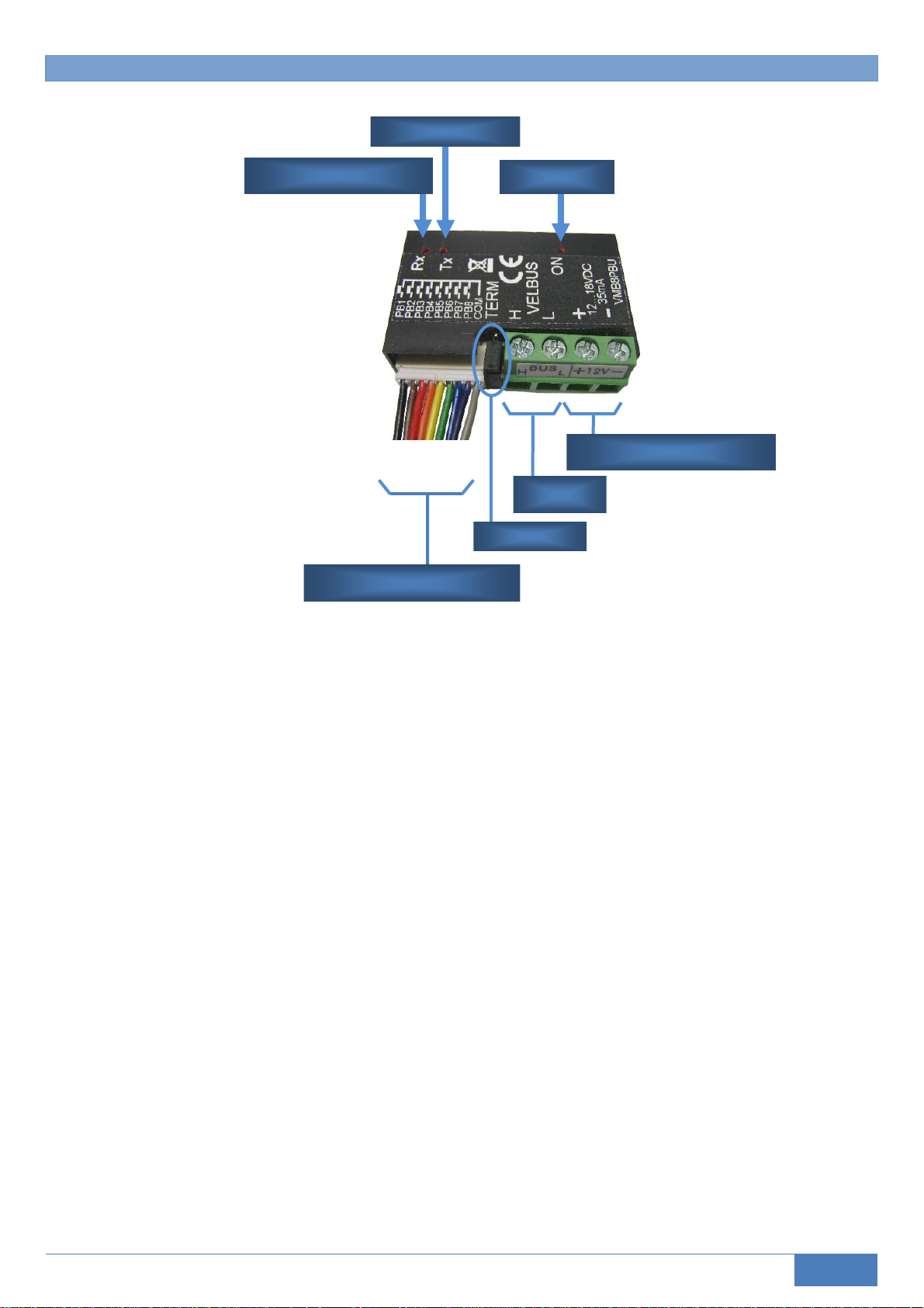
OVERVIEW
Velbus LED
Velbus Receiving LED
12345678C
Pushbutton connections
Terminator
Power LED
Velbus power supply
Velbus
VMB8PBU – ed.1 | 8-channel pushbutton module 5
Page 6

CONNECTION
To connect the Velbus modules with each other, a twisted pair cable is recommended (EIB 2x2x0.8mm², UTP
4x2x0.51mm² - CAT5 or equivalent).
When a lot of modules (more than 10) are connected on the Velbus cable or the Velbus cable is very long (over 50m)
it is important to foresee a cable with sufficient wire diameter (0.5mm
Connect the bus and power supply to the module (mind the polarity).
Connect the pushbuttons. Unused wires should be isolated.
2
of more).
Remark:
DO NOT extend the connection
wires for the pushbuttons
Connecting BTicinoTM pushbuttons
6 8-channel pushbutton module | VMB8PBU – ed.1
Page 7

Connecting a LED on a BTicinoTM pushbutton
Glue the blue (type VMBLDB) or amber (type VMBLDAB) LED on the pushbutton.
The black connection wire ‘PB’ of the LED is combined with one of the eight pushbutton connection wires.
The white connection wire ‘C’ of the LED is combined with the common connection wire ‘COM’ for the pushbuttons.
Connection wire
Pushbutton 1
‘PB’ connection wire LED
Common connection wire
for the pushbuttons
‘C’ connection wire LED
VMB8PBU – ed.1 | 8-channel pushbutton module 7
Page 8

Connecting NikoTM pushbuttons
Tip: Use ferrules on the wires for the pushbutton connections.
8 8-channel pushbutton module | VMB8PBU – ed.1
Page 9

Connecting a LED on a NikoTM pushbutton
Slide the blue (type VMBLDN) or amber (type VMBLDAN) LED into the slot of the pushbutton.
The black connection wire ‘PB’ of the LED is combined with one of the eight pushbutton connection wires.
The white connection wire ‘C’ of the LED is combined with the common connection wire ‘COM’ for the pushbuttons.
Use ferrules to combine the connection wires
Connect the wires to the pushbuttons.
Connection wire
Pushbutton 2
Common connection wire for
the pushbuttons
Connection wire
Pushbutton 1
‘PB’ connection wire
‘C’ connection wire
LED 1
‘C’ connection wire LED 1 ‘PB’ connection wire LED 2
VMB8PBU – ed.1 | 8-channel pushbutton module 9
Page 10

TERMINATOR
In normal circumstances only 2 ‘TERM’ terminators must be foreseen in a complete Velbus installation. Usually this
will be on one module inside the distribution box and on the module the furthest from the distribution box.
Remark:
In all other cases it must be removed.
In a wiring scheme with a lot of branches a
terminator is placed on a module inside the
distribution box and on the control panel
furthest from the distribution box. Should
communication problems occur, an additional
terminator can be placed on another branch.
However, the number of terminators should
be kept to a minimum as additional
terminators place a heavy load on the bus.
10 8-channel pushbutton module | VMB8PBU – ed.1
Page 11

USE
The pushbutton interface module is added to the Velbus system.
To all eight pushbuttons actions can be attributed to control relay channels e.g. switch them on or off, dim lights, open
or close window shutters and so on …
Configuration can only be done through the Velbuslink software.
Address:
Every module in the Velbus system must have a unique address.
Address setting is done by software.
Name:
Each button can be assigned a name (max. 16 characters) via the Velbuslink software. This can be very handy during
configuration of actions (controlling a relay, dimmer, window shutter…)
Response time:
Determines how long the pushbutton must be pushed for the action to take place. This can be immediately or after 1, 2
or 3 seconds.
Tip: For a pushbutton with action ‘All off’ it is better to configure a response time of 3 seconds.
Suppressing:
Unused pushbuttons may be suppressed.
Tip: To avoid accidental operation of the awing during wintertime, suppress those pushbuttons in winter and only make
them available during summertime.
Inversion:
It is possible to make a pushbutton act as being normally closed.
Hint: to connect magnetic contacts that are normally closed.
Multichannel pushbutton:
It is possible to control multiple channels via a single pushbutton. With every press on the button the next channel will
be selected. Different actions can be linked with each channel.
To change a pushbutton into a multichannel pushbutton the first and last channels must be set. Usually these are
identical to make the pushbutton act as a regular 1-channel pushbutton. When the last channel is set higher than the
first each push will select the next channel. When the last channel is reached, it loops back to the first
It is also possible to automatically jump back to the first channel when the pushbutton isn’t used for 3 seconds.
Hint: This multichannel pushbutton is extremely handy to call multiple dimming atmospheres with only one button.
Double-channel pushbutton:
It is possible to control two channels with only one pushbutton. A short press will control one channel while pushing
long will control the other. An action can be linked to each channel.
Enable this mode to change a regular into a double-channel pushbutton and set the first and last channel
A short push controls the first channel.
A long push controls the last channel.
The duration of the long push can be set to 1, 2 or 3 seconds.
Remark: when enabling double-channel mode, the multi-channel mode is disabled.
Suppressing:
Non-used pushbuttons can be suppressed.
VMB8PBU – ed.1 | 8-channel pushbutton module 11
Page 12

Lock/Unlock:
Pushbuttons can be locked (and unlocked) via the VelbusLink software to avoid unwanted actions. This locking can
also be done through other pushbuttons that are connected to the Velbus system.
This creates following possibilities:
• Lock a pushbutton as long as another Velbus pushbutton is closed.
• Lock a pushbutton as long as another Velbus pushbutton is open.
• Lock a pushbutton during a certain time by a push on another Velbus pushbutton. With the next push on that
other button it is possible to choose to relock or unlock the pushbutton.
Locking time can be permanent or set between:
o 1 sec and 2 min, in steps of 1 sec
o 2 min and 5 min, in steps of 15 sec
o 5 min and 30 min, in steps of 30 sec
o 30 min and 1 hour, in steps of 1 min
o 1 hour and 5 hours, in steps off 15 min
o 5 hours and 10 hours, in steps of 30 min
o 10 hours and 24 hours, in steps of 1 hour
o 2 or 3 days
• Unlock a pushbutton by a push on another Velbus pushbutton.
Hint: to avoid accidental control of the sunscreen during wintertime the pushbuttons can be locked during this period.
Backlighting:
The indication LED on the pushbutton may glow softly to locate the pushbutton in the dark. The brightness of the
backlighting can be adjusted. When desired, backlighting can be switched off completely.
Feedback:
The indication LED on the pushbutton can indicate the status of the action it controls. It can be on or off or when a
timer is running flash slowly or fast. If the flashing is disturbing, it can be changed to continuously on. It is also possible
to disable feedback.
Status feedback of a contact:
The identification LED on the pushbutton can also be used to indicate the status of a contact (open or closed). For
this, feedback must be disabled and the entry channel must be connected.
Hint: Useful to show the status of a magnetic contact.
Switching programs:
At certain points in time a pushbutton can be locked/unlocked or an action can be simulated. Up to 85 program steps
are possible.
A program step consists of following parts:
Channel
The concerned pushbutton (1...8) for which the program step is intended.
Program selection
Defines to which program a step belongs.
Following options are available:
• Summer program
• Winter program
• Holiday program
12 8-channel pushbutton module | VMB8PBU – ed.1
Page 13

Point in time
The time (day and hour) at which the program step is carried out.
• Day setting:
o A certain day of the week (Monday, Tuesday... Sunday)
o All working days (Monday through Friday)
o Every weekend (Saturday and Sunday)
o All days except Sunday
o All days of the week
o On date: a certain date (1...31) of a certain month (January ... December)
o Every month on a certain day (1...31) of every month
• Hour setting:
o At a certain hour (hour and minutes)
o At wake-up time 1 (plus or minus a number of quarters)
o At wake-up time 2 (plus or minus a number of quarters)
o At bed-time 1 (plus or minus a number of quarters)
o At bed-time 2 (plus or minus a number of quarters)
o At sunrise (plus or minus a number of quarters)
o At sunset (plus or minus a number of quarters)
Action
Following actions can be realized:
• Simulate a push on a pushbutton
• Simulate a long push on a pushbutton
• Simulate releasing a pushbutton
• Simulate pulse-control for which time-out can be set between:
o 0.25 sec
o 1 sec and 2 min, in steps of 1 sec
o 2 min and 5 min, in steps of 15 sec
o 5 min and 30 min, in steps of 30 sec
o 30 min and 1 hour, in steps of 1 min
o 1 hour and 5 hours, in steps of 15 min
o 5 hours and 10 hours, in steps of 30 min
o 10 hours and 18 hours, in steps of 1 hour
• Locking or unlocking a pushbutton
Activating/deactivating the switching program:
For each pushbutton the switching program can be activated or deactivated. This can be done via the VelbusLink
program or via pushbuttons that are connected to the Velbus.
Following functions can be realized:
• The switching program of a pushbutton is not executed as long as another Velbus pushbutton is closed.
• The switching program of a pushbutton is not executed as long as another Velbus pushbutton is open.
• The switching program of a pushbutton is not executed during a certain time-out period by a push on another
Velbus pushbutton. Choose to reactivate or deactivate the switching program next time the other pushbutton is
operated again.
The deactivation time can be permanent or set between:
o 1 sec and 2 min, in steps of 1 sec
o 2 min and 5 min, in steps of 15 sec
o 5 min and 30 min, in steps of 30 sec
o 30 min and 1 hour, in steps of 1 min
o 1 hour and 5 hours, in steps of 15 min
o 5 hours and 10 hours, in steps of 30 min
o 10 hours and 24 hours, in steps of 1 hour
o 2 or 3 days
• Activate the switching program for a pushbutton through a push on another Velbus pushbuttons.
Selection switching program:
There are 3 different program groups to choose from: summer, winter or holiday program. This can be done via the
VelbusLink software or via other pushbuttons that are connected to the Velbus system.Only the program steps that
belong to the program group are executed. If no program group is selected, no program steps will be executed.
VMB8PBU – ed.1 | 8-channel pushbutton module 13
Page 14

Alarm:
In the switching program it is possible to use two different wake-up times and two different sleep-times.
Setup is done via the VelbusLink software:
• Wake-up time in hours and minutes.
• Sleep-time in hours and minutes.
• Wake-up and sleep-times can be locally or global:
o Locally means the setting only applies to the selected module.
o Global means applicable for all modules that are set to ‘global’.
• The wake-up and sleep-times can be enabled or disabled:
o Enabled means that all program steps that use wake-up or sleep-times are executed.
o Disabled means that all program steps that use wake-up or sleep-times are not executed.
Activating/deactivating the alarm clock:
Programs that use wake-up or sleep-times can be activated or deactivated. This can be done through the Velbus
software or via pushbuttons connected to the Velbus.
Following options are available:
• Execute wake-up/sleep-time related programs as long as a Velbus pushbutton is closed.
• Execute wake-up/sleep-time related programs as long as a Velbus pushbutton is open.
• Do not execute wake-up/sleep-time related programs as long as a Velbus pushbutton is closed.
• Do not execute wake-up/sleep-time related programs as long as a Velbus pushbutton is open.
• Activate wake-up/sleep-time related programs via a push on a Velbus pushbutton.
• Activate/deactivate wake-up/sleep-time related programs via a push on a Velbus pushbutton.
• Deactivate wake-up/sleep-time related programs via a push on a Velbus pushbutton.
Sunrise and sunset:
The switching program allows the use of the time of sunrise and sunset.
Setting is done through the VelbusLink software:
• Timetable for sunrise and sunset
• Activate or deactivate sunrise related programs
• Activate or deactivate sunset related programs
Activating/deactivating sunrise and sunset related programs:
Programs that use sunrise or sunset times can be activated or deactivated. This can be done through the Velbus
software or via pushbuttons connected to the Velbus.
Following options are available:
• Execute sunrise/sunset time related programs as long as a Velbus pushbutton is closed.
• Execute sunrise/sunset time related programs as long as a Velbus pushbutton is open.
• Do not execute sunrise/sunset time related programs as long as a Velbus pushbutton is closed.
• Do not execute sunrise/sunset time related programs as long as a Velbus pushbutton is open.
• Activate sunrise/sunset time related programs via a push on a Velbus pushbutton.
• Activate/deactivate sunrise/sunset time related programs via a push on a Velbus pushbutton.
• Deactivate sunrise/sunset time related programs via a push on a Velbus pushbutton.
Date and time:
To allow the switching programs to function correctly the date and time must be set. This can be done through the
VelbusLink software, a control panel (VMB4PD) or a temperature controller (VMB1TC). Make sure one main clock is
set on a VMB4PD or VMB1TC in your Velbus installation to synchronize all clocks
14 8-channel pushbutton module | VMB8PBU – ed.1
Page 15

VERIFY SOFTWARE VERSION
The software version can be retrieved via the Velbuslink software.
Check the software version on http://www.velbus.eu
. When a newer version is available, download and install it.
VMB8PBU – ed.1 | 8-channel pushbutton module 15
Page 16

Velleman nv, Legen Heirweg 33, 9890 GAVERE
© 2011
16 8-channel pushbutton module | VMB8PBU – ed.1
 Loading...