

Page 1
V
M
V
M
V
4-channel 0 (1) to 10V output
dimmer controller
for Velbus system
B
B
4
4
D
D
C
C
C
D
4
B
M
Page 2

INDEX
INDEX ........................................................................................................................................... 2
DESCRIPTION ............................................................................................................................. 3
CHARACTERISTICS ................................................................................................................... 3
VELBUS CHARACTERISTICS ................................................................................................... 5
OVERVIEW ................................................... ................................................................... ............ 6
LED INDICATIONS ................................................................... ........ .... .... .... ....... .... .... .... ............ 7
LOCAL CONTROL .... ........ .... .... ... ........ .... .... .... ........ .... .... .... ........ .... .... .... ....... .... .... .... ........ ........ 8
USE ................................................... ................................................ ........................................... 9
Connection diagram with dimmable neon lighting ................................ ........ .... .... .... ........ .... .... 9
Connection diagram with power dimmers ..................................... ... .... .... ........ .... .... .... .... ...... 10
Connection diagram with a RGB LED dimmer ....................................................................... 11
Termination ............................................................................................................................. 12
Configuration........................................................................................................................... 13
Address: ..................................... ........................................................................... .............. 13
Dimmer delay: . .......................................................................................... .......................... 13
Switch-off delay: ............................................. ..................................................................... 13
Control functions: ................................................................................................................ 13
CHECKING THE SOFTWARE VERSION ................................................................................. 17
2 VMB4DC 4-channel dimmer controller module user manual – version 3
Page 3

DESCRIPTION
The module features four 0/1 to 10V outputs. Each output can accept one or more DC-controlled power dimmers
so as to dim lar ge groups of bulbs simultaneously.
The module also allows you to dim neon lighting equipped with a dimmable electronic starter with 1-10V control
input.
Controlling DC-controlled LED dimmers allows also an attractive ambient lighting.
Each channel can memorize several dimming functions and preset ambiances.
CHARACTERISTICS
Use:
• suitable for controlling DC-controlled power dimmers with 0/1-10V control input
• suitable for controlling DC-controlled LED dimmers with 0/1-10V control input
• suitable for dimming neon lighting equipped with a dimmable electronic starter with 1-10V control input
Outputs:
• 4 outputs with common (-) connection
• output voltage: 0 to 10V or 1 to 10V (adjus table per outpu t)
• max. output current: 10mA per output
• the output is protected against short-circuits and overvoltage
• galvanic separation between the output voltage and the Velbus power supply (3000VDC isolation)
LED indications:
• status indication for all 4 channels
o continuously lit: selected dimming level achieved
o slow blinking: timer running
o fast blinking: changing dimming level
o two short blinks: communication error
• power voltage present
• data reception and transfer over the Velbus
• status notification of the dimmer to the control modules
Module power supply:
• required power voltage: 12...18VDC
• consumption in stand-by: 45mA
• max. consumption: 100mA
Dimensions:
• standard DIN-rail housing: 2 modules
• L x W x H: 90 x 36 x 58mm
Configuration:
• only configurable via the Velbus PC interface (VMB1USB, VMB1RS or VMBRSUSB) and the Velbuslink
software
• addressing through software (up to 250 addresses)
• storage spac e for 37 different pushbuttons and t he ir function
• multiple functions and timer settings are configurable through software
• learned pushbuttons are saved in case of a power failure
Control:
• local control on the mod ule (on/off at short press, dimming at long press)
• through Velbus commands or pushbuttons connected to the Velbus system
• multiple control functions
o momentary
o off or slow off
o on or slow on
o on/off or slow on/off
o timer (start/stop, restartable or non-restartable)
o dimming (more or less intensity)
o more intensity
o less intensity
o moods
VMB4DC 4-channel dimmer controller module user manual – version 3 3
Page 4

o multistep dimmer
o output forced off
o output forced on
o output inhibition
Timer presets:
• only configurable through the Velbuslink software
• switch-off time configurable between
o 1 sec and 2 min in steps of 1 sec
o 2 min and 5 min in steps of 15 sec
o 5 min and 30 min in steps of 30 sec
o 30 min and 1 hour in steps of 1 min
o 1 hour and 5 hours in steps of 15 min
o 5 hours and 10 hours in steps of 30 min
o 10 hours and 24 hours in steps of 1 hour
o 2 days
o 3 days
o no switch-off timer
• dimming speed configurable between
o 2 sec and 2 min in steps of 1 sec
o 2 min and 5 min in steps of 15 sec
o 5 min and 30 min in steps of 30 sec
o 30 min and 1 hour in steps of 1 min
o 1 hour and 5 hours in steps of 15 min
o 5 hours and 10 hours in steps of 30 min
o 10 hours and 23 hours in steps of 1 hour
4 VMB4DC 4-channel dimmer controller module user manual – version 3
Page 5

VELBUS CHARACTERISTICS
• 2-wire communication for Velbus data and 2 wires for power
• data transfer: 16.6 kbit/s
• serial data protocol: CAN (Controller Area Network)
• short-circuit proof (towards (-) or (+) of power)
• bus error indication: 2 short blinks of the operation mode LED
• self-restoring after 25 seconds in case of a bus error
Possibility to assign a name (max. 16 characters) to each output channel.
The dimmer controller module can send following messages:
• dimmer status
• dimmer controlling module type (with software version)
• dimmer names
• communication error counter
• memory capacity
The dimmer controller module can send following commands:
• switch off LEDs on a control module
• switch on LEDs on a control module
• slow or fast blinking of the LEDs on a control module
The dimmer controller module can receive following messages:
• pushbutton module status
• fader status
The dimmer controller module can receive following commands:
• dimmer value setting
• to last-used dimming level
• stop dimming
• timer start
• recall dimmer status
• recall module type and software version
• recall communication error counter
• recall dimmer names
• recall memory contents
• overwrite memory contents
• switch off pushbutton indication LED
VMB4DC 4-channel dimmer controller module user manual – version 3 5
Page 6
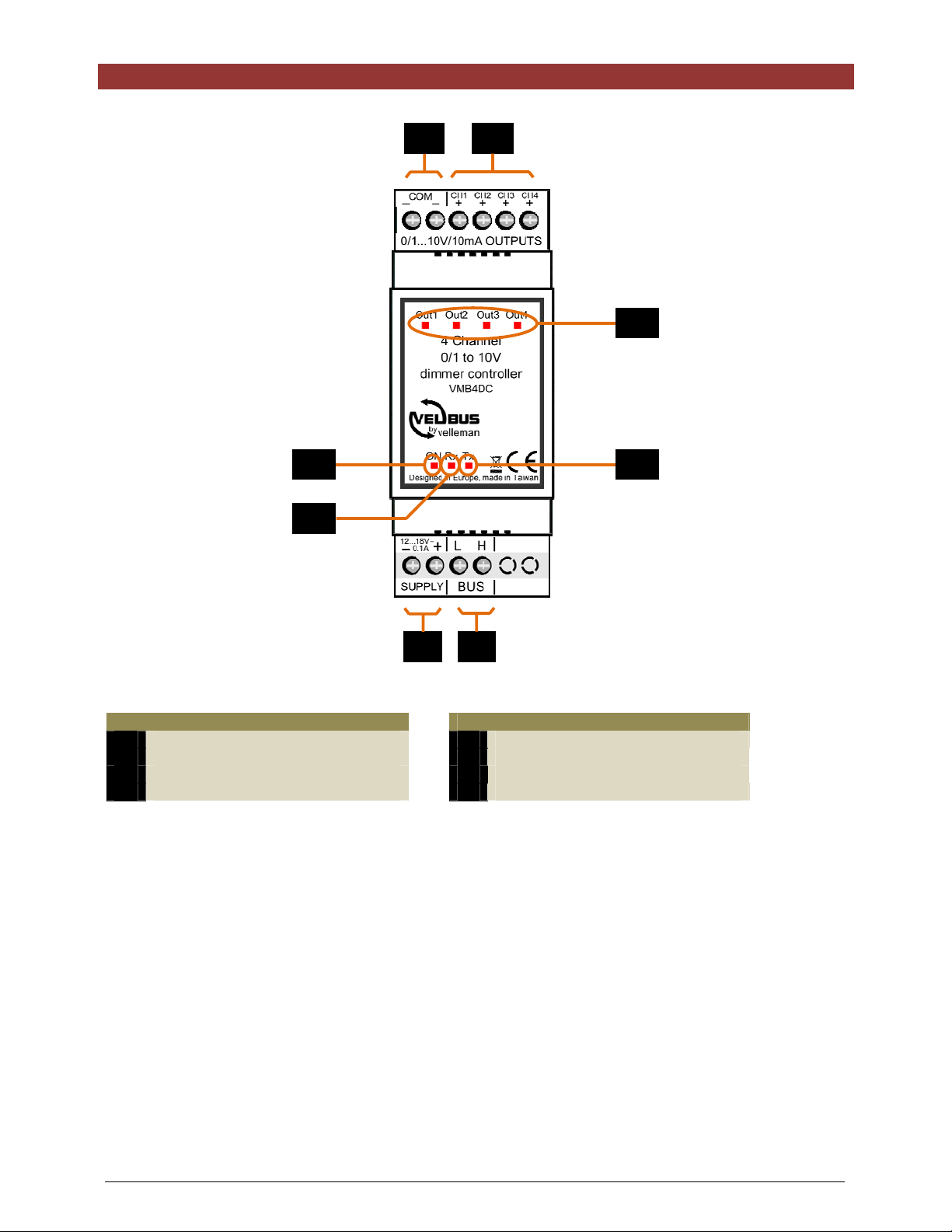
OVERVIEW
1
2
8
5 7
6
3 4
Connections
1
common (-) output
2
outputs
3
module or Velbus power supply
4
Velbus
5
6
7
8
power LED
Velbus RX (receive) LED
Velbus TX (transmit) LED
output status
LED indications
6 VMB4DC 4-channel dimmer controller module user manual – version 3
Page 7

LED INDICATIONS
Output LED:
• off when output voltage = 0V
• on when output voltage is stable
• blinks rapidly when o utput voltage
changes
• blinks slowly when switch-off delay
is running
On LED:
lights when power
voltage is prese nt
• blinks shortly twice at
communication error
Rx LED:
lights at Velbus data
reception
Tx LED:
lights at Velbus data transfer
VMB4DC 4-channel dimmer controller module user manual – version 3 7
Page 8

Remove the cover.
LOCAL CONTROL
Local control:
short press: enable or disable
the 0 or 10V output
long press: output voltage
modification between 0 and
10V (dimming)
8 VMB4DC 4-channel dimmer controller module user manual – version 3
Page 9

USE
The dimmer controller module is to be used with neon lighting equipped with a dimmable electronic starter using a
1-10V control signal, or with a DC-controlled p o we r d immer.
The module is entirely integrated into the Velbus system and controlled through the VMB4PD control panel or
through pushbuttons connected to a VMB8PB pushbutton interface.
To interconnect the Velbus modules it is recommended to use a twisted-pair cable (EIB 2x2x0.8mm2, UTP
8x0.51mm - CAT5 or equivalent).
Make sure to use a he av y - g a u ge wire (0.5mm
2
or more) in case of a multiple module connection (>10 modules) or
with log connections (>50m).
Connect the bus to the module (mind the po larity).
Connection diagram with dimmable neon lighting
The neon lighting must be equipped with a dimmable electronic ballast using a 1-10V control signal.
You can connect several neon tubes to 1 channel.
The Velbuslink program links every dim channel with a relay channel in momentary control so the voltage of the
neon tube drops at 0V in order to switch the lighting completely off.
VMB4DC 4-channel dimmer controller module user manual – version 3 9
Page 10

Connection diagram with power dimmers
In order to dim high-power lamps or a large group of lamps, it is possible to connect one or more DC-controlled
dimmers to the outputs of the dimmer controller.
Note that the 4 channels have 1 common (-) output.
10 VMB4DC 4-channel dimmer controller module user manual – version 3
Page 11

Connection diagram with a RGB LED dimmer
The dimmer controller can also be used to dim RGB LED strips through a DC-controlled RGB LED dimmer. Here,
3 channels are being used.
VMB4DC 4-channel dimmer controller module user manual – version 3 11
Page 12

Termination
Remove the cover.
Terminator
Generally, only 2 ‘TERM’ terminators must be used in a complete Velbus
®
installation. Usually, this will be on one
module inside the distribution box and on the module which is physically located furthest from the distribution box.
On all other modules, the terminator must be removed.
Remark:
In case of a wiring with multiple branches, only place a termination into a single module in the distribution box and
in the control panel which is the farthest from the distribution box. When communication problems occur, you can
place an extra termination on another branch. It is highly recommended to limit the number of terminations as too
large a number may overload the bus.
12 VMB4DC 4-channel dimmer controller module user manual – version 3
Page 13

Configuration
Address, dimmer delay, switch-off delay and control functions can only be configured through the Velbuslink
software.
Address:
Each module in the Velbus connection must have a unique address.
Configure the address through the software.
Dimmer dela y:
If the dimmer module will be used to dim neon lighting, link relay channel in a momentary control to the dimming
channel in order to switch the lamp on or off. As soon as the dimming value i s not 0 (zero), the relay channel will
be activated. To allow the lamp to ignite, you must set a dimming delay during which the lamp’s dimming process
will be briefly stalled.
The dimming delay and relay contact are not necessary when dimming neon lighting.
Switch-off delay:
The neon lighting’s dimming can be linked to a deactivation delay of the relay channel as soon as the dimming
value drops to 0%, this in order to prevent the lamp’s restart when dimming it off and on again.
This featur e is not necessary when dimming neon lighting.
Control functions:
The dimmer module is controlled through pushbuttons connected to the Velbus system via a pushbutton interface
or control panel.
You may assign up to 37 different pushbuttons. Each pushbutton may activate integrate a different function.
Function Description
1 Momentary
2 Off
3 Off with timers disabled
4 Off with timers disabled at
short press
5 Off with timers disabled at long
press
6 Slow off
7 On
8 On with timers disabled
9 On with timers disabled at
short press
10 On with timers disabled at long
press
The lighting remains switched on as long as the switch is closed.
The lighting is switched off.
In order to create an “all off” function, the same pushbutton of all
dimming channels will be configured as an off function.
The lighting is switched off and the timers cannot be restarted.
A short press of the pushbutton switches off the lighting but the
timers cannot be restarted.
A long press of the pushbutton switches off the lighting and the timers
remain enabled.
A short press of the pushbutton switches off the lighting and the
timers remain enabled.
A long press of the pushbutton switches off the lighting but the timers
cannot be restarted.
The lighting switches off slowly during a preset period.
The lighting switches on.
The lighting is switched on and the timers cannot be restarted.
A short press of the pushbutton switches on the lighting but the
timers cannot be restarted.
A long press of the pushbutton switches on the lighting and the timers
remain enabled.
A short press of the pushbutton switches on the lighting and the
timers remain enabled.
A long press of the pushbutton switches on the lighting but the timers
cannot be restarted.
11 Slow on
12 Toggle
13 Toggle with timers disabled
VMB4DC 4-channel dimmer controller module user manual – version 3 13
The lighting switches on slowly.
Each press toggles the lighting status.
Each press toggles the lighting status (on/off).
The timers cannot be started when the lighting is switched on.
Page 14

14 Toggle with timers disabled at
short press
Each press toggles the lighting status (on/off).
The timers cannot be started when the lighting was switched on by a
short press .
15 Toggle with timers disabled at
long press
16 Slow toggle
17 Start/stop timer
18 Start/stop timer met langzaam
aan/uit
19 Restartabl e t i mer
20 Restartable timer with slow
toggle
21 Non-restartable timer
22 Non-restartable timer with slow
toggle
Each press toggles the lighting status (on/off).
The timers cannot be started when the lighting was switched on by a
long press.
Each press switches the lighting slowly on or off.
A press of the pushbutton switches on the li ghting for a preset time.
A press of the pushbutton switches off the switched-on lighting
immediately.
A press of the pushbutton slowly switches on the lighting for a preset
time. The lighting switches off slowly afte r the preset t i me has
expired.
A press of the pushbutton switches off the switched-on l ighting
slowly.
A press of the pushbutton switches on the li ghting for a preset time.
A press of the pushbutton while the lighting is switched on restarts
the timer.
A press of the pushbutton switches on the l ighting slowly. The lighting
switches off slowly after the switch-off delay has expired.
A press of the pushbutton while the lighting is switched on restarts
the timer.
A press of the pushbutton switches on the li ghting for a preset time.
A press of the pushbutton while the lighting is switched on has no
effect.
A press of the pushbutton switches on the l ighting slowly. The lighting
switches off slowly after the switch-off delay has expired.
A press of the pushbutton while the lighting is switched on has no
effect.
23 Slow on at press, slow off at
release
24 Dimming up A press of the pushbutton increases the lighting’s intensity. The
25 On at short press
Dimming up at long press
26 Memory at short press
Dimming up at long press
27 Dimming down
28 Off at short press
Dimming down at long press
29 Dimming
At the press of the pushbutton the lighting switches on s lowly. At the
release of the pushbutton the lighting switches off slowly. The light ing
switches off slowly if the switch-off delay is expired while the
pushbutton is still being pressed.
lighting switches off after the switch-off del ay has expired.
A short press of the pushbutton switches the lighting fully on.
A long press dims up the lighting. The lighting’s intensity is
maintained at release. The lighting switches off after the switch-off
delay has expired.
A short press of the pushbutton switches on the lighting at the lastused intensity.
A long press dims up the lighting. The lighting’s intensity is
maintained at release. The lighting switches off after the switch-off
delay has expired.
A press of th e pushbutton decreases the lighting’s intensity. The
intensity is maintained at release of the pushbutton. The lighting
switches off after the switch-off delay has expi red.
A short press of the pushbutton switches the lighting fully off.
A long press dims down the lighting. The lighting’s intensity is
maintained at release. The lighting switches off after the switch-off
delay has expired.
A press of the pushbutton dims the lighting up or down. The intensity
is maintained at release of the pushbutton.
Repress the pushbutton to toggle the dimming direction. The lighting
switches off after the switch-off delay has expi red.
14 VMB4DC 4-channel dimmer controller module user manual – version 3
Page 15

30 Toggle at short press
Dimming at long press
A short press of the pushbutton switches the switched-off lighting fully
on or switches the switched-on lighting fully off.
A long press of the pushbutton dims the lighting up or down. The
intensity is maintained at release of the pushbutton. The lighting
switches off after the switch-off delay has expi red.
31 Memory at short press
Dimming at long press
32 Recalling a dimming
atmosphere
33 Fader dimming
34 Multistep dimmer
35 Forced off at closed switch
36 Forced off at open switch
37 Forced off
38 Enabling/disabling the forced-
off mode
39 Cancelling forced-off mode
A short press of the pushbutton switches on the switched-off lighting
at the last-used intensity or switches the switched-on lighting fully off.
A long press of the pushbutton dims the lighting up or down. The
intensity is maintained at release of the pushbutton. The lighting
switches off after the switch-off delay has expi red.
A press of the pushbutton recalls a pres et lighting intensity. The ramp
time to reach the preset lighting intensity and the switch-off delay can
also be programmed.
The fader’s position determines t he lighting’s intensit y.
A press of the pushbutton recalls the next preset lighting intensity.
The ramp time to reach the preset lighting intensity and the switch-off
delay can also be programmed.
The module can memorize up to 14 preset intensities. Default values
are 25, 50, 75, 100, 75, 50 and 25%.
The lighting cannot be switched on as long as the switch is closed.
The lighting cannot be switched on as long as the switch is open.
A press of th e pushbutton locks the lighting’s switch-on for a preset
time.
A press of th e pushbutton locks the lighting’s switch-on for a preset
time.
Repress the pushbutton to disable the forced-off mode.
A press of th e pushbutton cancels the f orced-off mode.
Remark:
The forced-off mode can still be determined through function 35 or 36
(Forced off at closed/open switch).
40 Forced on at closed switch
41 Forced on at open switch
42 Forced on
43 Enabling/disabling the forced-
on mode
44 Cancelling forced-on mode
The lighting is switched on as long as the switch is closed. All other
controls are ignored.
Remark:
The forced-off mode suppresses the forced-on mode.
The lighting is s wit c he d on as long as the switch is op en. A l l ot he r
controls are ignored.
Remark:
The forced-off mode suppresses the forced-on mode.
A press of the pushbutton switches on the l ighting. A l l other controls
are ignored for a preset time.
Remark:
The forced-off mode suppresses the forced-on mode.
A press of the pushbutton switches on the l ighting. A l l other controls
are ignored for a preset time.
Repress the pushbutton to disable the forced-on mode.
Remark:
The forced-off mode suppresses the forced-on mode.
A press of th e pushbutton cancels the f orced-on mode.
Remark:
The forced-on mode can still be determined through function 35 or 36
(Forced off at closed/open switch).
VMB4DC 4-channel dimmer controller module user manual – version 3 15
Page 16

45 Inhibition at closed switch
The lighting is switched off as long as the switch is closed. The
functions continue to operate internally.
The internal status is transferred to the lighting as soon as the switch
is opened.
46 Inhibition at open switch
47 Inhibition
48 Toggle inhibition mode
49 Cancelling inhibition
Some functions may be configurable with a switch-off time between
o 1 sec and 2 min in steps of 1 sec
o 2 min and 5 min in steps of 15 sec
o 5 min and 30 min in steps of 30 sec
o 30 min and 1 hour in steps of 1 min
o 1 hour and 5 hours in steps of 15 min
o 5 hours and 10 hours in steps of 30 min
o 10 hours and 24 hours in steps of 1 hour
o 2 days
o 3 days
o no switch-off timer
and a dimming speed between
o 2 sec and 2 min in steps of 1 sec
o 2 min and 5 min in steps of 15 sec
o 5 min and 30 min in steps of 30 sec
o 30 min and 1 hour in steps of 1 min
o 1 hour and 5 hours in steps of 15 min
o 5 hours and 10 hours in steps of 30 min
o 10 hours and 23 hours in steps of 1 hour
The lighting is swit c hed off as long as the s wit c h is op en . The
functions continue to operate internally.
The internal status is transferred to the lighting as soon as the switch
is closed.
A press of the pushbutton switches off the lighting for a preset time.
The functions continue to operate internally.
A press of the pushbutton switches off the lighting for a preset time.
The functions continue to operate internally. Repress the pushbutton
to cancel the inhibition mode.
A press of the pushbutton t ransfers the internal status to the relay .
16 VMB4DC 4-channel dimmer controller module user manual – version 3
Page 17

CHECKING THE SOFTWARE VERSION
The software version can be verified via the Velbus link software.
Check on http://www.velbus.eu
Connect the Velbus interface to a PC and run the upgrade-software and follow the instructions on the screen.
Remark:
Upgrading a module is not without risk. Do not interrupt the p rocess!
If for any reason the upgrade should fail, the module will cease normal operation. The module will have to be
returned to the manufacturer.
whether you have the latest version. If a newer version is available, download it.
VMB4DC 4-channel dimmer controller module user manual – version 3 17
Page 18

Refer to our website for more information: www.velbus.be
18 VMB4DC 4-channel dimmer controller module user manual – version 3
 Loading...