

Page 1
VMB1TSW
Temperature sensor module
for the Velbus system
Page 2

CONTENTS
DESCRIPTION ................................................................................................................................ 3
CHARACTERISTICS ...................................................................................................................... 3
VELBUS CHARACTERISTICS ...................................................................................................... 5
OVERVIEW SENSOR MODULE .................................................................................................... 7
EMBEDDING THE TEMPERATURE SENSOR .............................................................................. 8
EMBEDDING A TEMPERATURE SENSOR TOGETHER WITH A CONTROLLER ...................... 9
OVERVIEW HEATING INSTALLATION ....................................................................................... 10
WIRING ......................................................................................................................................... 11
Connecting the temperature sensor VMB1TS ............................................................................................................ 11
Connecting the temperature controller VMB1TC / VMB1TCW(W) ............................................................................ 11
Relay cabinet wiring ................................................................................................................................................... 12
Terminator .................................................................................................................................................................. 13
Addressing .................................................................................................................................................................. 13
LED INDICATION ......................................................................................................................... 13
Anti-freeze, night, day or comfort mode ..................................................................................................................... 13
Cooling or heating mode ............................................................................................................................................ 14
Air-conditioner or heater active ................................................................................................................................... 14
OPERATION ................................................................................................................................. 15
SETTINGS .................................................................................................................................... 16
Preset range ............................................................................................................................................................... 16
Protecting the circulation pump and/or heating valves ............................................................................................... 16
Time statistics ............................................................................................................................................................. 16
Minimum and maximum temperature ......................................................................................................................... 17
Differential thermostat ................................................................................................................................................ 17
Factory settings .......................................................................................................................................................... 17
CONFIGURING THE OUTPUTS .................................................................................................. 18
REMOTE CONTROL .................................................................................................................... 19
SWITCHING TO ANTI FREEZE MODE THROUGH WINDOW CONTACTS ............................... 20
DIFFERENTIAL THERMOSTAT .................................................................................................. 21
The passage automatically 3° cooler than the office .................................................................................................. 22
Passive cooling of a bedroom .................................................................................................................................... 23
Page 3

DESCRIPTION
The sensor module can be used to measure and send temperatures over the Velbus-system. In combinatio n with a
relay module (VMB4RYNO / VMB4RYLD or VMB1RY) a thermostat can be set-up to control a heating or cooling
installation.
Setting the comfort, day, night or anti-freeze mode can be done via the local pushbutton of with pushbuttons that are
connected to the Velbus. Different sensors can be configured and controlled from a remote location through a
temperature controller (VMB1TC / VMB1TCW) or via a PC interface (VMB1USB, VMB1RS or VMBRSUSB) and the
Velbus link software.
The temperature controller (VMB1TC / VMB1TCW) can also include program instructions to control different sensors.
CHARACTERISTICS
Temperature range of the sensor: -10° to 63.5°C (14° to 146°F)
precision after calibration:
±0.5°C at 25°C
±1°C between -10°C and 63.5°C
Resolution: 0.0625°C
Hysteresis: 0°C to 15.5°C (interval of 0.5°C)
Possibility to automatically send the ambient temperature over the Velbus
Registration of minimum and maximum temperature
Registration on-time of heater/air-conditioner
Thermostat function for cooling or heating
In combination with a second sensor a differential thermostat can be created
Range:
heating function: -32°C to 54°C in steps of 0.5°C (default settings: 5° to 30°)
cooling function: -32°C to 54°C in steps of 0.5°C (default settings: 16° to 36°C)
Relay steering via Velbus for:
heating
fast heating/cooling
heating boiler in day mode
cooling
steering circulation pump
alarm at low temperature
alarm at high temperature
Cycling protection delay on heating and cooling outputs (minimum on/off switching delay): 1 minute defaul t (can be
switched off or set in multiples of minutes via Velbuslink software)
Selectable unjamming function for the circulation pump and/or heating valves (min. 1 minute/day on)
Control:
local pushbutton
remotely via pushbuttons connected to the Velbus
via temperature controller VMB1TC / VMB1TCW
through Velbus program instructions
Local control for switching between:
comfort mode
day mode
night mode
safeguard mode (anti-freeze)
Possibility to prevent (lock) local control
Control through pushbuttons connected to the Velbus to:
set the module to comfort temperature
set the module to day temperature
set the module to night temperature
set the module to safeguard temperature (anti-freeze)
set the thermostat to heating
set the thermostat to cooling
lock the local control
unlock the local control
Heating can be set in anti freeze mode through window contacts conne cted to the Velbus when a window is opened
Feedback to the pushbutton modules to update the LED status
Can be programmed without the aid of a PC
Simple learning process by pressing the desired pushbuttons while in learning mode
Page 4

Storage capacity of 10 different pushbuttons per control function
LED indications for:
thermostat function for cooling
comfort mode
day mode
night mode
heater/air-conditioning status
power supply voltage
receiving/transmitting data over the Velbus
Settings for:
the desired temperature
the desired comfort temperature for heating
the desired day temperature for heating
the desired night temperature for heating
the anti-freeze safeguard temperature
the heating limit (upper limit of the heating preset range)
the desired comfort temperature for cooling
the desired day temperature for cooling
the desired night temperature for cooling
the lower limit of the cooling preset range
the upper limit of the cooling preset range
the hysteresis
calibration of the sensor
the temperature difference for fast heating/cooling or for the differential thermostat
the low temperature alarm (alarm when temperature drops below this value)
the high temperature alarm (alarm when temperature rises above this value)
the duration of temporary mode: from 1 to 65.279 minutes (45 days, 7 hours, 59 minutes)
transmitting the current temperature over the Velbus:
o only when requested
o only when changes occur
o at specific time intervals, selectable between 10 and 255 seconds (4 minutes 15 seconds)
resetting minimum and maximum temperature
the zone (each sensor can belong to a specific zone)
the address of the linked sensor to set up a differential thermostat
cycling protection delay (minimum on/off switching delay)
Change settings through Velbus instructions or via a temperature controller (VMB1TC / VMB1TCW)
Control through a program stored in a temperature controller (VMB1TC / VMB1TCW)
Different modes:
automatic: the sensor module accept all program instructions
temporary manual: program instructions are ignored during a specific period of time
manual: all program instructions are ignored and local control is locked
The learned pushbutton functions and settings are retained when voltage drop-outs occu r
246 possible addresses (setting via rotary switches)
Required power supply: 12 to 18VDC
Consumption when not in use: 12mA
Maximal consumption: 15mA
Dimensions (W x H x D): 43 x 46 x 22mm
Page 5

VELBUS CHARACTERISTICS
2-wire communication for Velbus data and 2 wires for power supply
data transmission: 16.6 Kbit/s
Serial data protocol: CAN (Controller Area Network)
Short circuit proof (towards negative or positive pole of the power supply)
LED indication when receiving or transmitting data over the Velbus
bus error indication: 2 short flashes of the LEDs
auto recovering after 25 seconds when a bus error occurs
The sensor module can be given a designation with a maximum of 16 characters.
The temperature sensor module can transmit following messages:
output status
manual pushbutton status
sensor status
sensor temperature, minimum and maximum temperature
time statistics (heating/air-conditioning on time)
sensor settings
sensor configuration
module type (including zone number and software version)
sensor name
memory content
the communication error counter
The temperature sensor module can transmit following instructions:
change the status of the LED(s) on the pushbutton module
switching off the LED(s) on a pushbutton module
switching on the LED(s) on a pushbutton module
make LED(s) on a pushbutton module flash slowly
make LED(s) on a pushbutton module flash fast
the desired temperature for the linked sensor to create a differential thermostat
The temperature sensor module can receive following messages:
the status of a pushbutton module
The temperature sensor module can receive following instructions:
to set:
the desired temperature
the desired comfort temperature for heating
the desired day temperature for heating
the desired night temperature for heating
the anti-freeze safeguard temperature
the heating limit
the desired comfort temperature for cooling
the desired day temperature for cooling
the desired night temperature for cooling
the lower limit of the cooling preset range
the upper limit of the cooling preset range
the hysteresis
calibration of the sensor
the temperature difference for fast heating/cooling or for the differential thermostat
the temperature difference for fast heating or cooling
the alarm temperatures
the default duration of temporary mode (sleep time)
the zone number
the address of the linked sensor to set up a differential thermostat
to determine:
heating
cooling
local control panel:
lock
unlock
Page 6

memory:
read
(over)write
set the status of the output LED
switching off the indication LED on the pushbutton module(s)
switch unjam function of circulation pump and/or heating valve on or off
output LED handling:
switch off
switch on
flash
flash slowly
flash (very) fast
request:
module type
content of the communication error counter
the sensor temperature (min/max) and setting the time interval for transmitting data
the time statistics
the sensor status
the sensor settings
the sensor configuration
the sensor name
resetting:
minimum temperature
maximum temperature
time statistics
switching to:
comfort mode
day mode
night mode
anti-freeze mode
Page 7
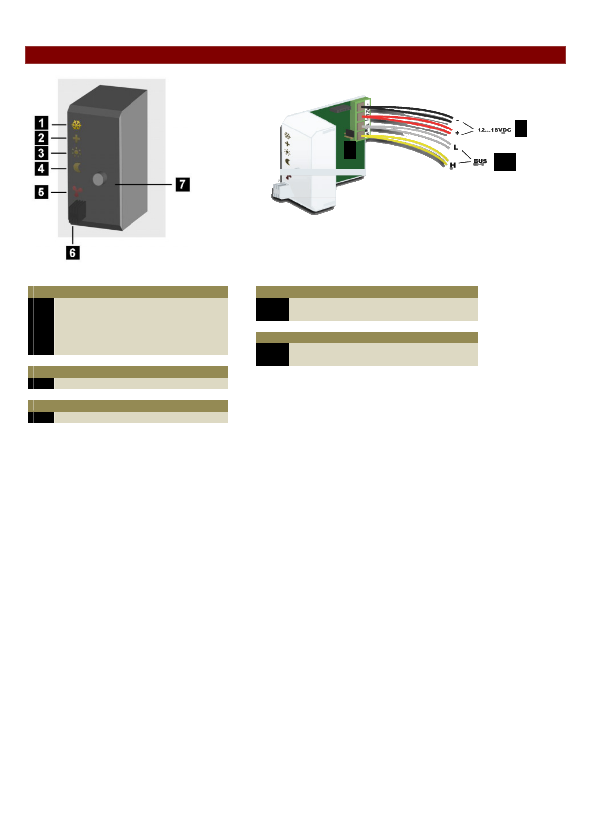
OVERVIEW SENSOR MODULE
9
8
10
LED indication
Cooling mode
1
Comfort mode
2
Day mode
3
Night mode
4
Heating or air-conditioning on
5
Sensor
Temperature sensor
6
Controls
Mode pushbutton
7
8
Terminator
Power supply 12 to 18Vdc
9
Velbus
10
Settings
Wiring
Page 8
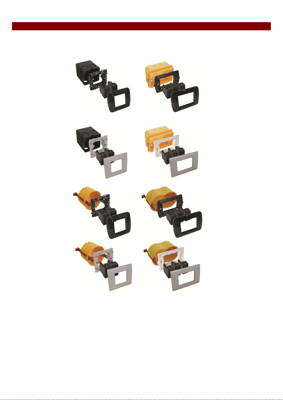
EMBEDDING THE TEMPERATURE SENSOR
The temperature sensor VMB1TSW can be embedded in combination with blank frames VMBFBI and cover plate.
It is possible to use a 2- or 3-module wide frame with cover plate from the BTicino Living series.
The module must be pushed into the build-in frame from the front.
It is also possible to use a 3-module wide frame with cover plate from the BTicino Light or Light Tech series.
The module must be pushed into the build-in frame from the front.
To build the sensor in into a hollow wall, use a hollow wall pattress.
Page 9

EMBEDDING A TEMPERATURE SENSOR TOGETHER WITH A CONTROLLER
The sensor (VMB1TSW) can be embedded together with a controller (VMB1TC / VMB1TCW) in a 4-module wide
frame with cover plate from the BTicino Living series. The module must be pushed into the build-in frame from the
front.
The sensor (VMB1TS) can be build-in together with a controller (VMB1TC / VMB1TCW) in a 4-module wide frame
with cover plate from the BTicino Light of Light Tech series. The module must be pushed into the build-in frame from
the front
To build the controller and sensor in into a hollow wall, use a hollow wall pattress.
Page 10

OVERVIEW HEATING INSTALLATION
A heating installation usually consists of radiators or convectors, a boiler, circulation pump and a collector with valves
for every radiator group. Every room is equipped with a temperature sensor VMB1TSW which is controlled by one or
multiple temperature controllers VMB1TC / VMB1TCW(W). The sensors in turn steer the relay modules VMB4RYNO /
VMB4RYLD (or VMB1RY) that control the valves. As soon as one of the valves is opened, a relay channel can
activate the circulation pump and when one of the sensors is in day or comfort mode, a relay channel can put the
boiler in day mode. When convectors with built-in fan are used, a relay channel can steer this fan in case the room
temperature deviates too much from the desired temperature, e.g. to speed up heating in the morning.
Page 11

WIRING
To interconnect the Velbus modules the use of twisted-pair cable (EIB 2x2x0.8mm2, UTP 8x0.51mm - CAT5 or
equivalent) is recommended.
When a lot of modules (more than 10) are connected to the cable or longer cable lengths (more than 50m) are used, it
is important to use a cable with appropriate diameter (0.5mm² or higher).
Connect the bus to the module (beware of the polarity).
Connect the 12V to 18V direct current to the module (beware of the polarity).
Connecting the temperature sensor VMB1TS
Connecting the temperature controller VMB1TC / VMB1TCW(W)
Page 12

Relay cabinet wiring
Page 13

Terminator
Normally only 2 ‘TERM’ terminators must be used in a complete Velbus installation. Usually this will be on the end
of 2 bus wires (for example in the attic and in the basement.
On all other modules, the terminator must be removed.
Remark:
In case the wiring contains a lot of branches, still a terminator will be set on the end of 2 bus wires (= 2 terminators).
When communication errors occur, an additional terminator can be set as close as possible to one of the two existing
terminators. However, the number of terminators should be limited as more terminators place a heavy load on the bus
(max 3).
Addressing
Every module on the Velbus system must have its own unique address.
The address of the temperature controller VMB1TCW is set via a Velbuslink©
LED INDICATION
Anti-freeze, night, day or comfort mode
In rooms that have a temperature sensor VMB1TS the heating (or air-conditioning) can be set in 4 different modes:
comfort, day, night or anti-freeze. Every mode has its own desired temperature setting. The selected mode is
indicated with LEDs. The sensor module is set to anti-freeze mode when the comfort, day and night mode LEDs are
off. When the comfort, day or night mode LED is flashing, the sensor module is set temporarily (sleep timer) to the
indicated mode and normal program is suspended during that ‘sleep’ time.
Anti-freeze Night Day Comfort
Page 14

Cooling or heating mode
When the temperature sensor is configured to control an air-conditioning system, the frost flower LED (upper LED)
will be lit. Setting the heating or cooling mode can only be done through a temperature controller (VMB1TC /
VMB1TCW) or through the Velbus link program.
Heating mode Cooling mode
Air-conditioner or heater active
When the heater (valve open) or air-conditioner is active, a red LED will be lit.
The red output LED can indicate following error conditions:
Flashing (short on, long off): the heater/cooler should be off but it did not
receive the command from the relays module.
Flashing (short off, long on): the heater/cooler should be on but it did not
receive the command from the relays module.
Fast flashing: configuration of the sensor chip failed.
Note: as long as the error condition exists the output status wil be retransmitted every minute.
Page 15

OPERATION
Pushing the push button repeatedly will switch the module between anti-freeze, night, day or comfort mode
successively.
When the comfort, day or night mode LED is flashing, the sensor module is set temporarily (sleep timer) to the
indicated mode. During this time the program is ignored
When the sleep timer expires, the sensor module will resume the program or in case no program is present will return
to its previous setting.
Remarks:
Anti-freeze mode can not be set temporarily.
Standard time is set through the temperature controller.
Overriding temporary mode can be done by pushing and holding the push button. The LED stops flashing and the
sensor remains in the selected mode until the next program step is executed.
Local operation can be locked or unlocked via a temperature controller VMB1TCW or via the Velbus link program.
When the sensor module is set to manual mode via a temperature controller VMB1TCW or vi a the Velbus link
program, local operation will be locked.
Page 16

SETTINGS
Following parameters can be set via the temperature controller (see manual VMB1TC / VMB1TCW(W)) or via the
Velbus link software:
the zone to which the sensor belongs
the operating mode (heating or cooling)
switching the unjam function of the circulation pump and/or heating valve on or off
the desired comfort temperature for heating
the desired day temperature for heating
the desired night temperature for heating
the anti-freeze safeguard temperature
the heating limit (upper limit of the heating preset range)
the temperature difference for fast heating/cooling or for the differential thermostat
the desired comfort temperature for cooling
the desired day temperature for cooling
the desired night temperature for cooling
the lower limit of the cooling preset range
the upper limit of the cooling preset range
the hysteresis
calibration of the sensor
the alarm temperatures
the duration of temporary mode
the zone number
the low temperature alarm (alarm when temperature drops below this value)
the high temperature alarm (alarm when temperature rises above this value)
the duration of temporary mode: from 1 to 65.279 minutes (45 days, 7 hours, 59 minutes)
transmitting the current temperature over the Velbus:
o only when requested
o only when changes occur
o at specific time intervals, selectable between 10 and 255 seconds (4 minutes 15 seconds)
resetting minimum and maximum temperature
reset time registration for the heater/air-conditioning
locking or unlocking local control
the address of the linked sensor to set up a differential thermostat
sensor name (max. 16 characters)
The cycling protection delay (delay setting is 1 minute) can be modified through the Velbuslink software if the
software version of the sensor module is 0949 or higher (see “Verify software version”).
Preset range
The preset range for the desired temperature can be adjusted by the user.
This is a way to make sure that the heating can never be set higher than a certain value.
Protecting the circulation pump and/or heating valves
When a circulation pump or a valve is not being used for some time, it might get stuck. To avoid this, an unjamming
function can be enabled which activates the pump or opens the valve for at least one minute every day.
Enabling of disabling the unjam function can be done via the temperature controller (VMB1TC / VMB1TCW) or
through the Velbus link software via a PC connected to the Velbus PC interface (VMB1USB, VMB1RS of
VMBRSUSB).
Time statistics
For every mode (comfort, day, night or anti-freeze) the time during which the heating or air-conditioning was one is
stored. These statistics can be recalled or reset via the temperature controller (VMB1TC / VMB1TCW) or through the
Velbus link software via a PC connected to the Velbus PC interface (VMB1USB, VMB1RS of VMBRSUSB).
Page 17

Minimum and maximum temperature
The sensor records the minimum and maximum temperature.
These values can be examined or reset via the temperature controller (VMB1TC / VMB1TCW) or through th e Velbus
link software via a PC connected to the Velbus PC interface (VMB1USB, VMB1RS of VMBRSUSB).
Differential thermostat
Using two sensors a differential thermostat can be created. When the difference in temperature between b oth sensors
reaches a certain value, the relay channel can be activated.
To achieve this, the first sensors must know the address of the second one. The second sensor must than be linked
to a relay channel. The temperature difference value is set on the first sensor.
Factory settings
After receiving this module, following factory default settings are already stored into the sensor:
Description Factory default
Zone number No zone
Differential sensor address None
Operating mode Heating
Unjam heating valve Disabled
Unjam heating valve circulation pump Disabled
Desired comfort temperature for heating 22°C
Desired day temperature for heating 20°C
Desired night temperature for heating 15°C
Anti-freeze safeguard 5°C
Heating limit 30°C
Temperature difference (fast heating/cooling or differential thermostat) 3°C
Calibration factor -2.5°C
Hysteresis 0.5°C
Desired comfort temperature for cooling 21°C
Desired day temperature for cooling 23°C
Desired night temperature for cooling 26°C
Lower limit cooling preset range 16°C
Upper limit cooling preset range 36°C
Low temperature alarm 3°C
High temperature alarm 30°C
Default duration temporary mode (sleep timer) 1 hour
Time interval for automatic transmission temperature Disabled
Local control Unlocked
Cycling protection delay 1 minute
Page 18

CONFIGURING THE OUTPUTS
The sensor module transmit messages over the Velbus when the status of one of its multiple outputs changes. Relay
modules (VMB1RY or VMB4RYNO / VMB4RYLD) can be linked to these Velbus messages to perform following
functions:
steering the heating valve
switching the heating or cooling installation to boost mode when the difference in desired and current temperature
is too big
set the heating boiler in day mode
steering the air-conditioning
steering the circulation pump of the heating installation
generate an alarm when the temperature is too low (heating system down)
generate an alarm when the temperature is too high (a valve does not close anymore)
Every relay channel that is steered by a temperature sensor must be set to momentary (instant) control.
The way to allocate those relay channels is through the use of the Velbus link software via a PC connected to a
Velbus PC interface (VMB1USB, VMB1RS of VMBRSUSB).
Page 19

REMOTE CONTROL
The sensor module can be operated locally, but also remotely via a temperature controller VMB1TC / VMB1TCW(W)
(refer to the manual of the controller).
The sensor module can also be operated remotely by connecting pushbutton s to the Velbus.
Pushbuttons can be defined for:
setting the sensor module mode to comfort
setting the sensor module mode to day
setting the sensor module mode to night
setting the sensor module mode to anti-freeze
setting the sensor module mode to heating
setting the sensor module mode to cooling
lock the local operation of the sensor module
unlock the local operation of the sensor module
For every operating function up to 10 different pushbuttons can be assigned. The easiest way to assign those
pushbuttons is by using the Velbus link software using a PC that is connected to a Velbus PC interface (VMB1USB,
VMB1RS of VMBRSUSB).
Page 20

SWITCHING TO ANTI FREEZE MODE THROUGH WINDOW CONTACTS
The heating can be switched automatically in anti freeze mode as soon as a window featuring window contacts is
opened. The LEDs will switch off on the VMB1TS temperature sensor. The VMB1TC / VMB1TCW(W) temperature
controller displays an anti freeze and key symbol together with a blinking mode LED.
Locatie
Badkamer
- 0m 18
↑
Mode
←
Menu
→
↓
The heating cannot be set into another mode as long as a window remains open. Once all windows closed, the
heating will swith to the initial mode. The used contacts may be of the NO or the NC type, and may be connected to a
VMB8PB push-button interface or a VMB6IN input module. You can connect maximum 10 NO and 10 NC contacts to
the sensor module.
Assign the contacts through Velbuslink software and a PC connected the Velbus interface (VMB1USB, VMB1RS or
VMBRSUSB). The NC contacts (i.e. contacts closed when window is closed) must be connected to the “Normal
closed disable switch” function of the sensor module. The NO contacts (i.e. contacs ope n when the window is closed)
must be connected to the “Normal open disable switch” function of the sensor module.
Page 21

DIFFERENTIAL THERMOSTAT
Using two sensors, a differential thermostat can be created. When the temperature difference between both sensors
crosses a preset value, a relay channel can be activated.
To achieve this, the first sensors must know the address of the second one. The second sensor must than be linked
to a relay channel. The temperature difference value is set on the first sensor.
The settings can be done via a temperature controller VMB1TC / VMB1TCW(W) or via the Velbus link program.
Schematic overview differential thermostat (sensor2 in heating mod e):
SENSOR1
SENSOR2
Set-up:
Differential sensor address =
address sensor2
Temp. Difference ∆t = -10°...10°
t1
Measured temp t1 + ∆t
Schematic overview differential thermostat (sensor2 in coolin g mode):
SENSOR1
Set-up:
Differential sensor address =
address sensor2
Temp. Difference ∆t = -10°...10°
t2
= Desired temperature for sensor2
Remark:
if t1+ ∆t > t
(mode2 = anti-freeze, night, day or comfort)
SENSOR2
t1
Measured temp t1 + ∆t
Refer to some applications of a differential thermostat below.
t2
= Desired temperature for sensor2
Remark: if t1+ ∆t < t
t
(mode2 = anti-freeze, night, day or comfort)
mode2
mode2
Set-up:
heating
heating on when t1+ ∆t > t2
than desired temp. sensor2 = t
Set-up:
cooling
Cooler on when t1+ ∆t < t2
than desired temp. sensor2 =
mode2
mode2
Page 22

The passage automatically 3° cooler than the office
When the sensor module in the office is set to day-mode, the temperature in the passage must be 3° lower than the
office. Is the day temperature of the office is set to 20°C the desired passage temperature will be 17°C.
When the sensor module in the office is set to night-mode, the temperature in the passage must be 3° lower than the
office. Is the night temperature of the office is set to 15°C the desired passage temperature will be 12°C.
Office
Configuration:
The way to configure the system is to use the Velbus link program via a PC connected on the Velbus PC interface
(VMB1USB, VMB1RS of VMBRSUSB).
The configuration is now finished and the differential thermostat is enabled.
Remarks:
Make sure both sensors are in heating mode (frost flower LED on the sensor is off).
The passage temperature can never be higher than the prefe rred setting of its selected mode (anti-freeze, night,
day or comfort).
Passage
Page 23

Passive cooling of a bedroom
During summer time the bedroom is cooled via a fan that extracts air from a cooler room.
Mount a temperature sensor in both rooms. The temperature sensor of the bedroom is set to cooling mode and the
Cooler room
Bedroom
cooling output is linked to a relay channel that controls the fan.
When the temperature in the cooler room is about 3 degrees lower than the bedroom temperature the fan is activated.
Configuration:
The way to configure the system is to use the Velbus link program via a PC connected on the Velbus PC interface
(VMB1USB, VMB1RS of VMBRSUSB).
The configuration is now finished and the differential thermostat is enabled.
Remark:
The cooling will stop when the bedroom temperature reaches the preferred sett ing of its selected mode (anti-freeze,
night, day or comfort).
Page 24

Refer to our website for more information: www.velbus.be
 Loading...