

Page 1
VMB1TS
Temperature sensor module
for the Velbus system
VMB1TS manual – edition 2 1
Page 2

CONTENTS
DESCRIPTION ........................................................................................................................... 3
CHARACTERISTICS .................................................................................................................. 3
VELBUS CHARACTERISTICS ................................................................................................... 5
OVERVIEW SENSOR MODULE ................................................................................................. 7
EMBEDDING THE TEMPERATURE SENSOR ........................................................................... 8
EMBEDDING A TEMPERATURE SENSOR TOGETHER WITH A CONTROLLER ...................... 9
OVERVIEW HEATING INSTALLATION ................................................................................... 10
WIRING .................................................................................................................................... 11
Connecting the temperature sensor VMB1TS................................................................................. 11
Connecting the temperature controller VMB1TC ............................................................................. 11
Relay cabinet wiring ..................................................................................................................... 12
Terminator ................................................................................................................................... 13
Addressing .................................................................................................................................. 13
LED INDICATION..................................................................................................................... 14
Anti-freeze, night, day or comfort mode ......................................................................................... 14
Cooling or heating mode ............................................................................................................... 14
Air-conditioner or heater active ...................................................................................................... 14
OPERATION ............................................................................................................................ 15
SETTINGS ............................................................................................................................... 16
Preset range ................................................................................................................................ 16
Zones .......................................................................................................................................... 16
Protecting the circulation pump and/or heating valves ..................................................................... 16
Time statistics .............................................................................................................................. 17
Minimum and maximum temperature ............................................................................................. 17
Differential thermostat .................................................................................................................. 17
Factory settings............................................................................................................................ 17
CONFIGURING THE OUTPUTS ............................................................................................... 18
Allocate a relay channel to control a valve...................................................................................... 19
Allocate a relay channel to control the fan (boost)........................................................................... 20
Allocate a relay channel to set the boiler in day mode ..................................................................... 21
Allocate a relay channel to steer an air-conditioner ......................................................................... 22
Allocate a relay channel for the circulation pump ............................................................................ 23
Allocate a relay channel for the low temperature alarm ................................................................... 24
Allocate a relay channel for the high temperature alarm .................................................................. 25
REMOTE CONTROL ................................................................................................................ 26
Remotely control comfort mode ..................................................................................................... 27
Remotely control day mode........................................................................................................... 28
Remotely control night mode......................................................................................................... 29
Remotely control anti-freeze mode ................................................................................................ 30
Remotely set heating mode........................................................................................................... 31
Remotely set cooling mode ........................................................................................................... 32
Remotely lock local operation........................................................................................................ 33
Remotely unlock local operation .................................................................................................... 34
Deleting an assigned pushbutton................................................................................................... 35
Deleting all assigned pushbuttons for a certain function .................................................................. 36
Deleting all assigned pushbuttons ................................................................................................. 37
SWITCHING TO ANTI FREEZE MODE THROUGH WINDOW CONTACTS .............................. 38
DIFFERENTIAL THERMOSTAT ............................................................................................... 39
The passage automatically 3° cooler than the office ....................................................................... 40
Passive cooling of a bedroom ....................................................................................................... 41
VERIFY SOFTWARE VERSION ............................................................................................... 42
2 VMB1TS manual – edition 2 – rev.3
Page 3

DESCRIPTION
The sensor module can be used to measure and send temperatures over the Velbus-system. In combination with a
relay module (VMB4RY or VMB1RY) a thermostat can be set-up to control a heating or cooling installation.
Setting the comfort, day, night or anti-freeze mode can be done via the local pushbutton of with pushbuttons that are
connected to the Velbus. Different sensors can be configured and controlled from a remote location through a
temperature controller (VMB1TC) or via a PC interface (VMB1USB, VMB1RS or VMBRSUSB) and the Velbus link
software.
The temperature controller (VMB1TC) can also include program instructions to control different sensors.
CHARACTERISTICS
◊ Temperat ure range of the sensor: -10° to 63.5°C (14° to 146°F)
◊ precision after calibration:
• ±0.5°C at 25°C
• ±1°C between -10°C and 63.5°C
◊ Resolution: 0.0625°C
◊ Hysteresis: 0°C to 15.5°C (interval of 0.5°C)
◊ Possibility to automatically send the ambient temperature over the Velbus
◊ Registration of minimum and maximum temperature
◊ Registration on-time of heater/air-conditioner
◊ Thermostat function for cooling or heating
◊ In combination with a second sensor a differential thermostat can be created
◊ Range:
• heating function: -32°C to 54°C in steps of 0.5°C (default settings: 5° to 30°)
• cooling function: -32°C to 54°C in steps of 0.5°C (default settings: 16° to 36°C)
◊ Relay steering via Velbus for:
• heating
• fast heating/cooling
• heating boiler in day mode
• cooling
• steering circulation pump
• alarm at low temperature
• alarm at high temperature
◊ Cycling protection delay on heating and cooling outputs (minimum on/off switching delay): 1 minute default (can be
switched off or set in multiples of minutes via Velbuslink software)
◊ Selectable unjamming function for the circulation pump and/or heating valves (min. 1 minute/day on)
◊ Control:
• local pushbutton
• remotely via pushbuttons connected to the Velbus
• via temperature controller VMB1TC
• through Velbus program instructions
◊ Local control for switching between:
• comfort mode
• day mode
• night mode
• safeguard mode (anti-freeze)
◊ Possibility to prevent (lock) local control
◊ Control through pushbuttons connected to the Velbus to:
• set the module to comfort temperature
• set the module to day temperature
• set the module to night temperature
• set the module to safeguard temperat ure (anti-freeze)
• set the thermostat to heating
• set the thermostat to cooling
• lock the local control
• unlock the local control
◊ Heating can be set in anti freeze mode through window contacts connected to the Velbus when a window is opened
◊ Feedback to the pushbutton modules to update the LED status
◊ Can be programmed without the aid of a PC
◊ Simple learning process by pressing the desired pushbuttons while in learning mode
VMB1TS manual – edition 2 3
Page 4

◊ Storage capacity of 10 different pushbuttons per control function
◊ LED indications for:
• thermostat function for cooling
• comfort mode
• day mode
• night mode
• heater/air-conditioning status
• power supply voltage
• receiving/transmitting data over the Velbus
◊ Settings for:
• the desired temperature
• the desired comfort temperature for heating
• the desired day temperature for heating
• the desired night temperature for heating
• the anti-freeze safeguard temperature
• the heating limit (upper limit of the heating preset range)
• the desired comfort temperature for cooling
• the desired day temperature for cooling
• the desired night temperature for cooling
• the lower limit of the cooling preset range
• the upper limit of the cooling preset range
• the hysteresis
• calibration of the sensor
• the temperature difference for fast heating/cooling or for the differential thermostat
• the low temperature alarm (alarm when temperature drops below this value)
• the high temperature alarm (alarm when temperature rises above this value)
• the duration of temporary mode: from 1 to 65.279 minutes (45 days, 7 hours, 59 minutes)
• transmitting the current temperature over the Velbus:
o only when requested
o only when changes occur
o at specific time intervals, selectable between 10 and 255 seconds (4 minutes 15 seconds)
• resetting minimum and maximum temperature
• the zone (each sensor can belong to a specific zone)
• the address of the linked sensor to set up a differential thermostat
• cycling protection delay (minimum on/off switching delay)
◊ Change settings through Velbus instructions or via a temperature controller (VMB1TC)
◊ Control through a program stored in a temperature controller (VMB1TC)
◊ Different modes:
• automatic: the sensor module accept all program instructions
• temporary manual: program instructions are ignored during a specific period of time
• manual: all program instructions are ignored and local control is locked
◊ The learned pushbutton functions and settings are retained when voltage drop-outs occur
◊ 246 possible addresses (setting via rotary switches)
◊ Required power supply: 12 to 18VDC
◊ Co ns umpt io n w hen not i n use: 12mA
◊ Maximal consumption: 15mA
◊ Dime nsions (W x H x D): 43 x 46 x 22mm
4 VMB1TS manual – edition 2 – rev.3
Page 5

VELBUS CHARACTERISTICS
• 2-wire communication for Velbus data and 2 wires for power supply
• data transmission: 16.6 Kbit/s
• Serial data protocol: CAN (Controller Area Network)
• Short circuit proof (towards negative or positive pole of the power supply)
• LED indication when receiving or transmitting data over the Velbus
• bus error indication: 2 short flashes of the LEDs
• auto recovering after 25 seconds when a bus error occurs
The sensor module can be given a designation with a maximum of 16 characters.
The temperature sensor module can transmit following messages:
• output status
• manual pushbutton status
• sensor status
• sensor temperature, minimum and maximum temperature
• time statistics (heating/air-conditioning on time)
• sensor settings
• sensor co nfig ur at ion
• module type (including zone number and software version)
• sensor name
• memory content
• the communication error counter
The temperature sensor module can transmit following instructions:
• change the status of the LED(s) on the pushbutton module
• switching off the LED(s) on a pushbutton module
• switching on the LED(s) on a pushbutton module
• make LED(s) on a pushbutton module flash slowly
• make LED(s) on a pushbutton module flash fast
• the desired temperature for the linked sensor to create a differential thermostat
The temperature sensor module can receive following messages:
• the status of a pushbutton module
The temperature sensor module can receive following instructions:
• to set:
the desired temperature
the desired comfort temperature for heating
the desired day temperature for heating
the desired night temperature for heating
the anti-freeze safeguard temperature
the heating limit
the desired comfort temperature for cooling
the desired day temperature for cooling
the desired night temperature for cooling
the lower limit of the cooling preset range
the upper limit of the cooling preset range
the hysteresis
calibration of the sensor
the temperature difference for fast heating/cooling or for the differential thermostat
the temperature difference for fast heating or cooling
the alarm temperatures
the default duration of temporary mode (sleep time)
the zone number
the address of the linked sensor to set up a differential thermostat
• to determine:
heating
cooling
VMB1TS manual – edition 2 5
Page 6

• local control panel:
lock
unlock
• memory:
read
(over)write
• set the status of the output LED
• switching off the indication LED on the pushbutton module(s)
• switch unjam function of circulation pump and/or heating valve on or off
• out p ut LED ha ndli ng:
switch off
switch on
flash
flash slowly
flash (very) fast
• request:
module type
content of the communication error counter
the sensor temperature (min/max) and setting the time interval for transmitting data
the time statistics
the sensor status
the sensor settings
the sensor configuration
the sensor name
• resetting:
minimum temperature
maximum temperature
time statistics
• switching to:
comfort mode
day mode
night mode
anti-freeze mode
6 VMB1TS manual – edition 2 – rev.3
Page 7
(
(
(
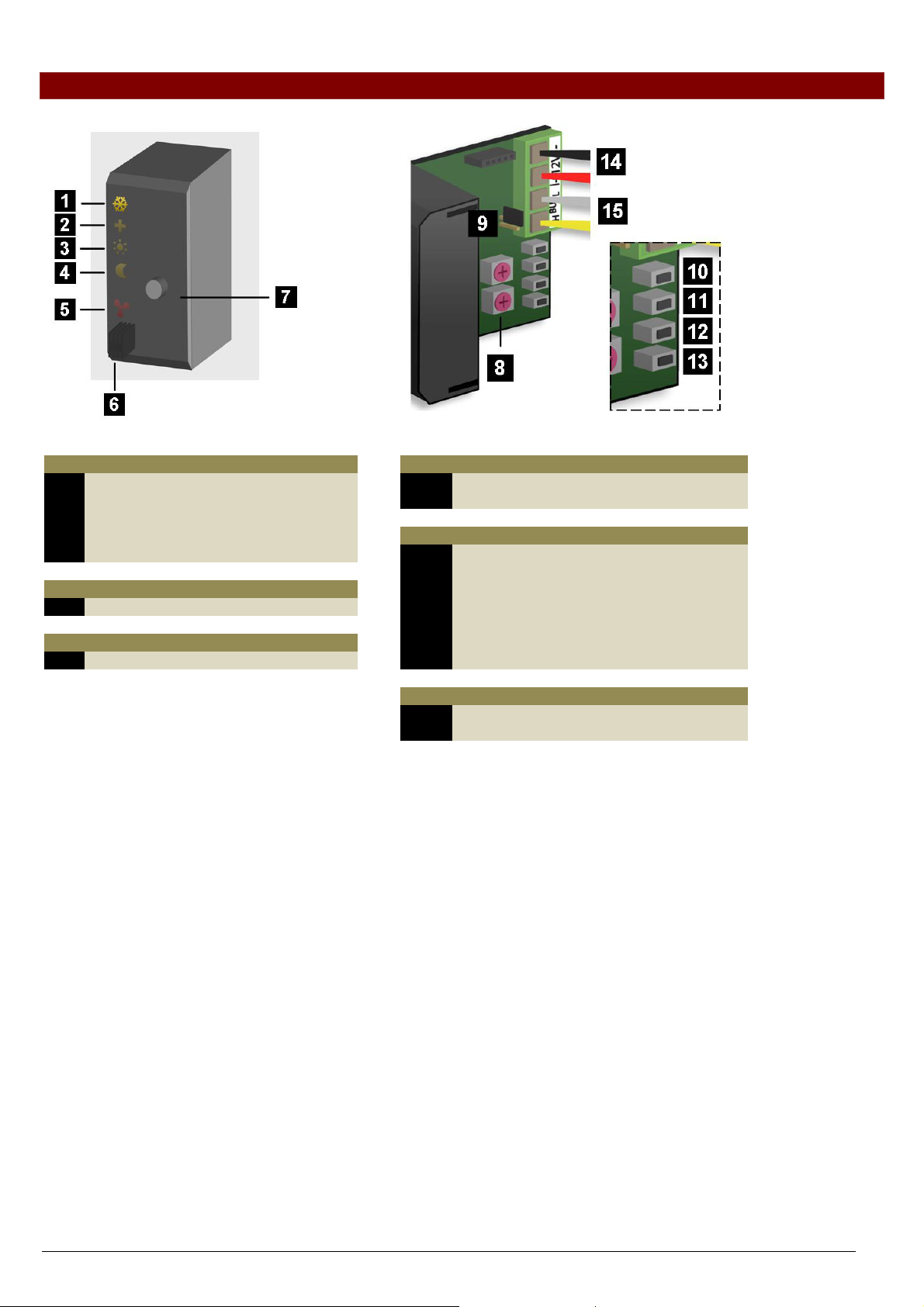
OVERVIEW SENSOR MODULE
COOL
DAY
BOOST
HEAT
LED indication
1 Cooling mode
2 Comfort mode
3 Day mode
4 Night mode
5 Heating or air-conditioning on
Sensor
6 Temperature sensor
Controls
7 Mode pushbutton
8 Address setting
9 Terminator
10 (COOL) cooler
11 (DAY) central heating system in day mode
12 (BOOST) boost heater/cooler
13 (HEAT) heater
7+11
7+12
7+13
Mode + DAY) high temp.alarm
Mode + BOOST) low temp.alarm
Mode + HEAT) pump
14 Power supply 12 to 18Vdc
15 Velbus
Settings
Manual control
Wiring
VMB1TS manual – edition 2 7
Page 8
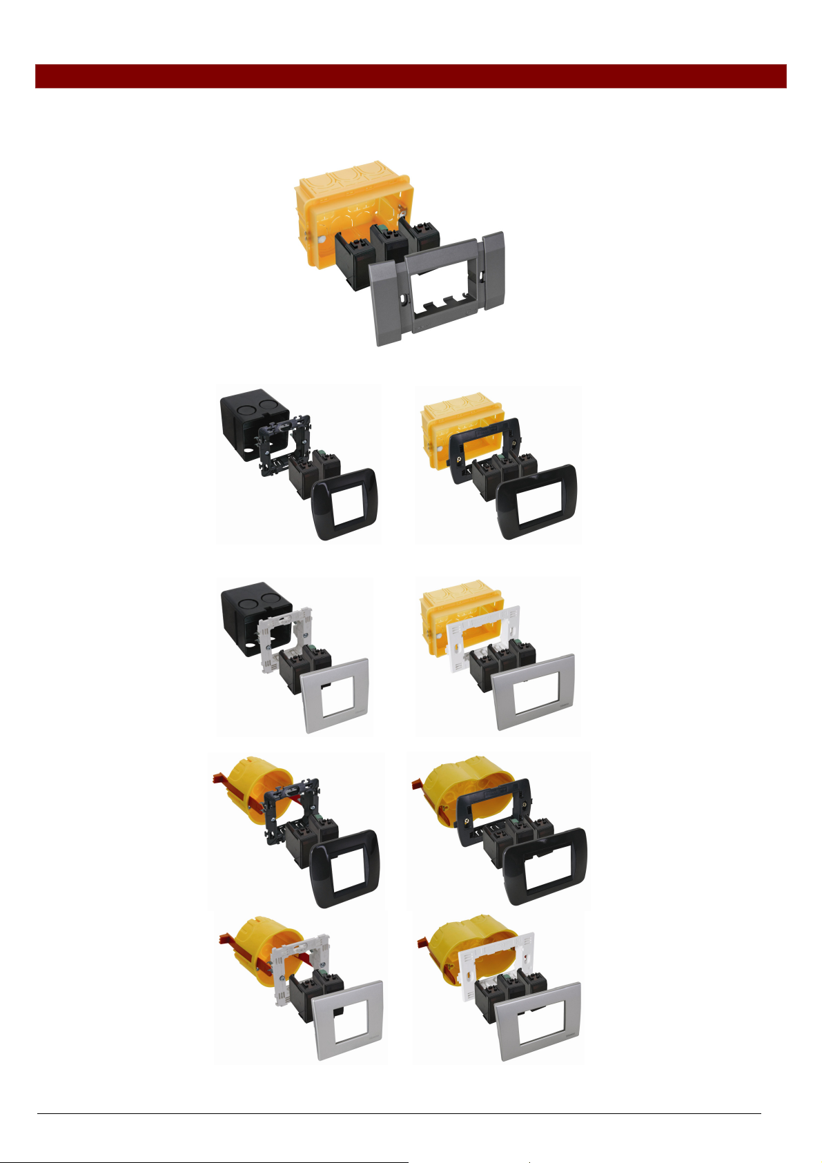
EMBEDDING THE TEMPERATURE SENSOR
The temperature sensor VMB1TS can be embedded in combination with 2 blank frames VMBFBI and a Velbus cover
plate VMBFDG or VMBFLG.
Push the modules from the back into the cover plate
It is also possible to use a 2- or 3-module wide frame with cover plate from the BTicino Living series.
The module must be pushed into the build- in frame from the front
It is also possible to use a 3-module wide frame with cover plate from the BTicino Light or Light Tech series.
The module must be pushed into the build- in frame from the front.
To build the sensor in into a hollow wall, use a hollow wall pattress.
8 VMB1TS manual – edition 2 – rev.3
Page 9
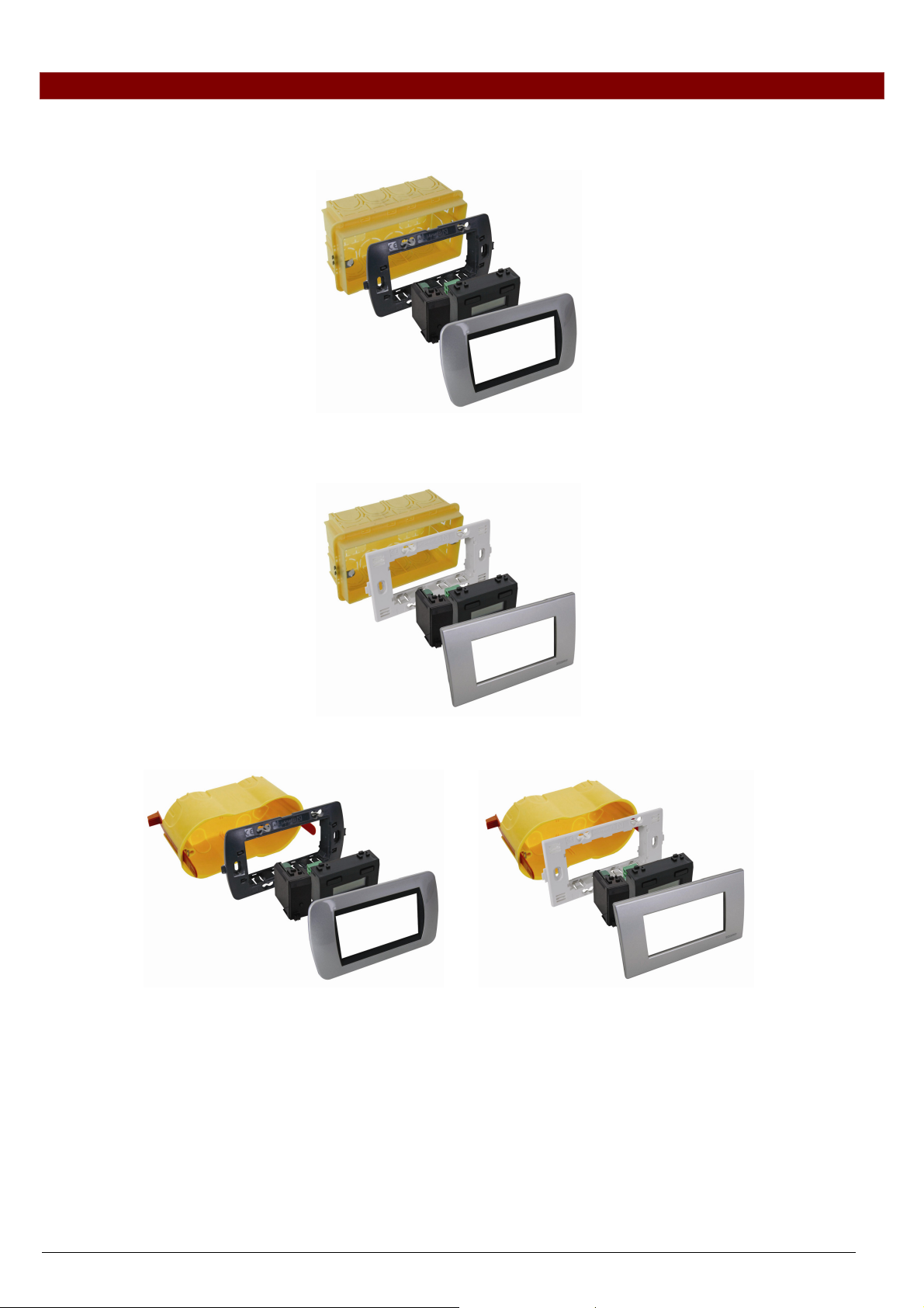
EMBEDDING A TEMPERATURE SENSOR TOGETHER WITH A CONTROLLER
The sensor (VMB1TS) can be embedded together with a controller (VMB1TC) in a 4-module wide frame with cover
plate from the BTicino Living series. The module must be pushed into the build-in frame from the front.
The sensor (VMB1TS) can be build-in together with a controller (VMB1TC) in a 4-module wide frame with cover plate
from the BTicino Light of Light Tech series. The module must be pushed into the build-in frame from the front
To build the controller and sensor in into a hollow wall, use a hollow wall pattress.
VMB1TS manual – edition 2 9
Page 10
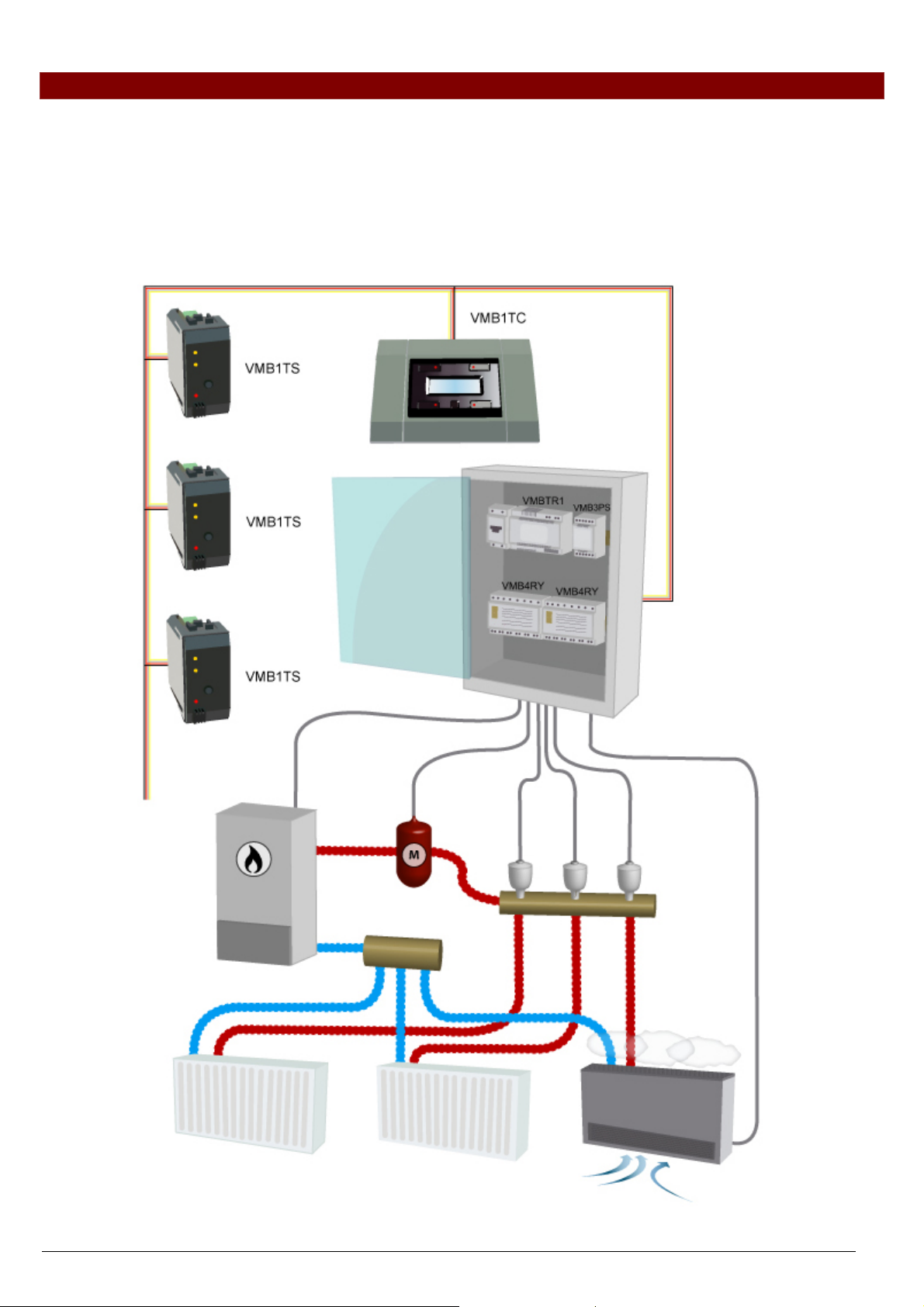
OVERVIEW HEATING INSTALLATION
A heating installation usually consists of radiators or convectors, a boiler, circulation pump and a collector with valves
for every radiator group.
Every room is equipped with a temperature sensor VMB1TS which is controlled by one or multiple temperature
controllers VMB1TC. The sensors in turn steer the relay modules VMB4RY (or VMB1RY) that control the valves. As
soon as one of the valves is opened, a relay channel can activate the circulation pump and when one of the sensors
is in day or comfort mode, a relay channel can put the boiler in day mode.
When convectors with built-in fan are used, a relay channel can steer this fan in case the room temperature deviates
too much from the desired temperature, e.g. to speed up heating in the morning.
10 VMB1TS manual – edition 2 – rev.3
Page 11
WIRING
To interconnect the Velbus modules the use of twisted-pair cable (EIB 2x2x0.8mm2, UTP 8x0.51mm - CAT5 or
equivalent) is recommended.
When a lot of modules (more than 10) are connected to the cable or longer cable lengths (more than 50m) are used, it
is important to use a cable with appropriate diameter (0.5mm² or higher).
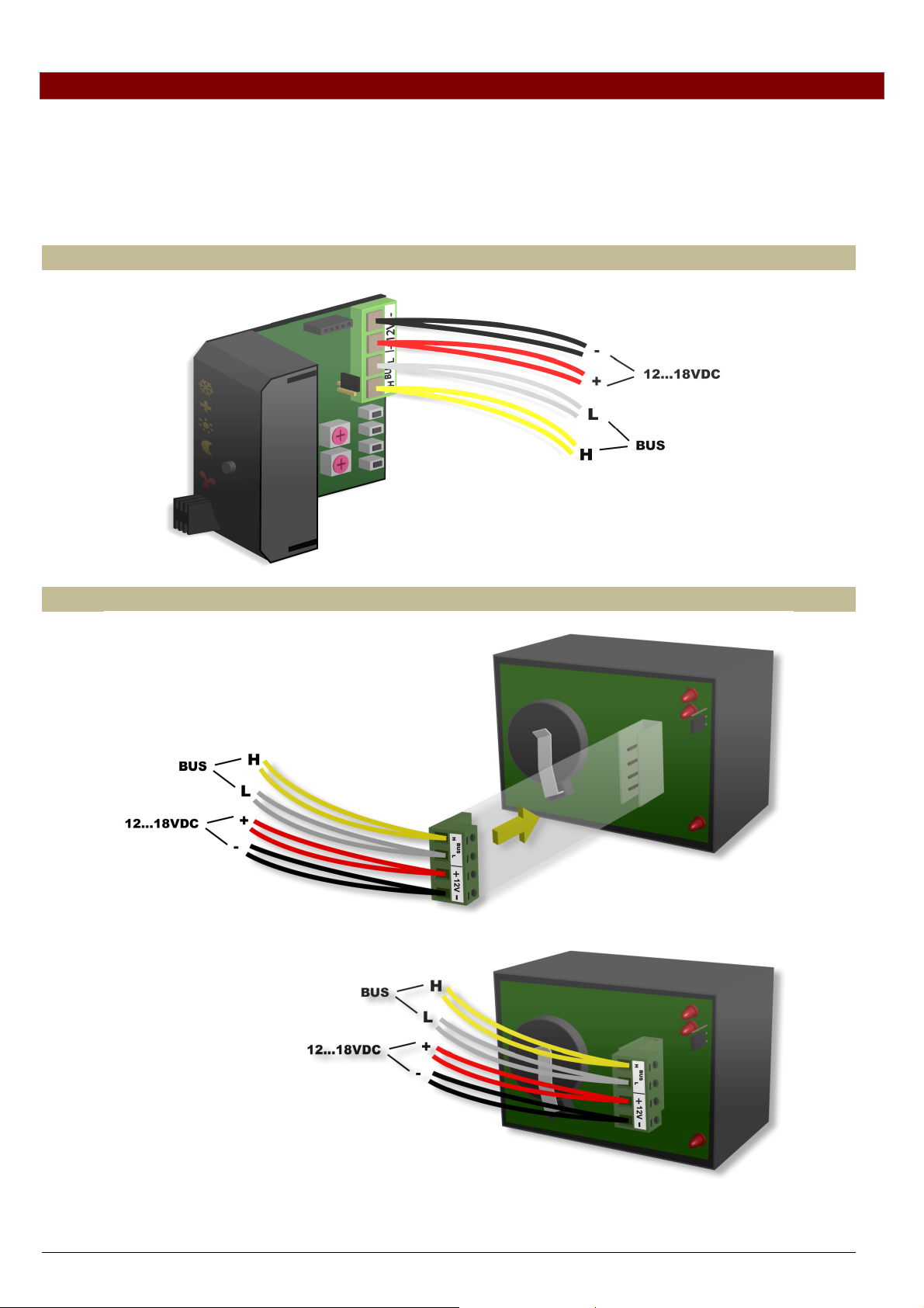
Connect the bus to the module (beware of the polarity).
Connect the 12V to 18V direct current to the module (beware of the polarity).
Connecting the temperature sensor VMB1TS
BUS TWISTED PAIR (0.5mm²)
Connecting the temperature controller VMB1TC
VMB1TS manual – edition 2 11
Page 12
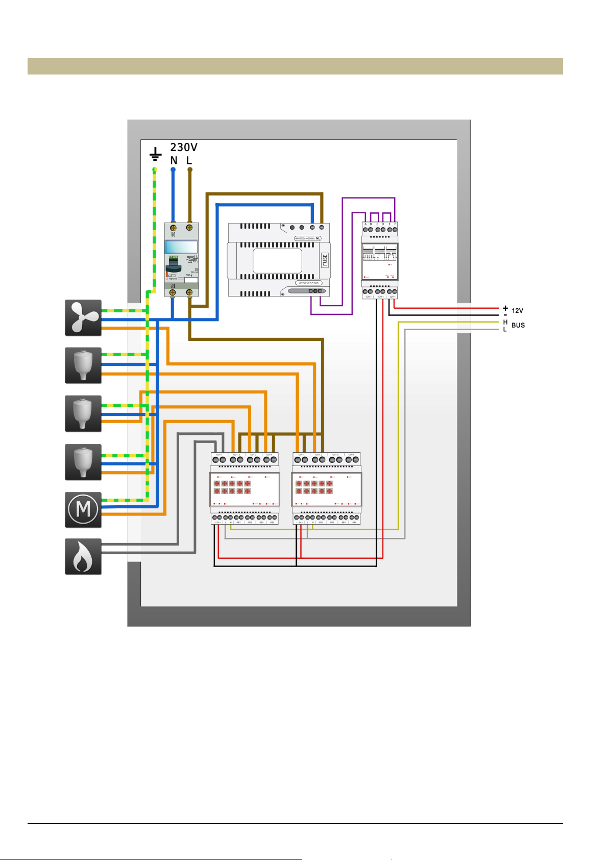
Relay cabinet wiring
12 VMB1TS manual – edition 2 – rev.3
Page 13
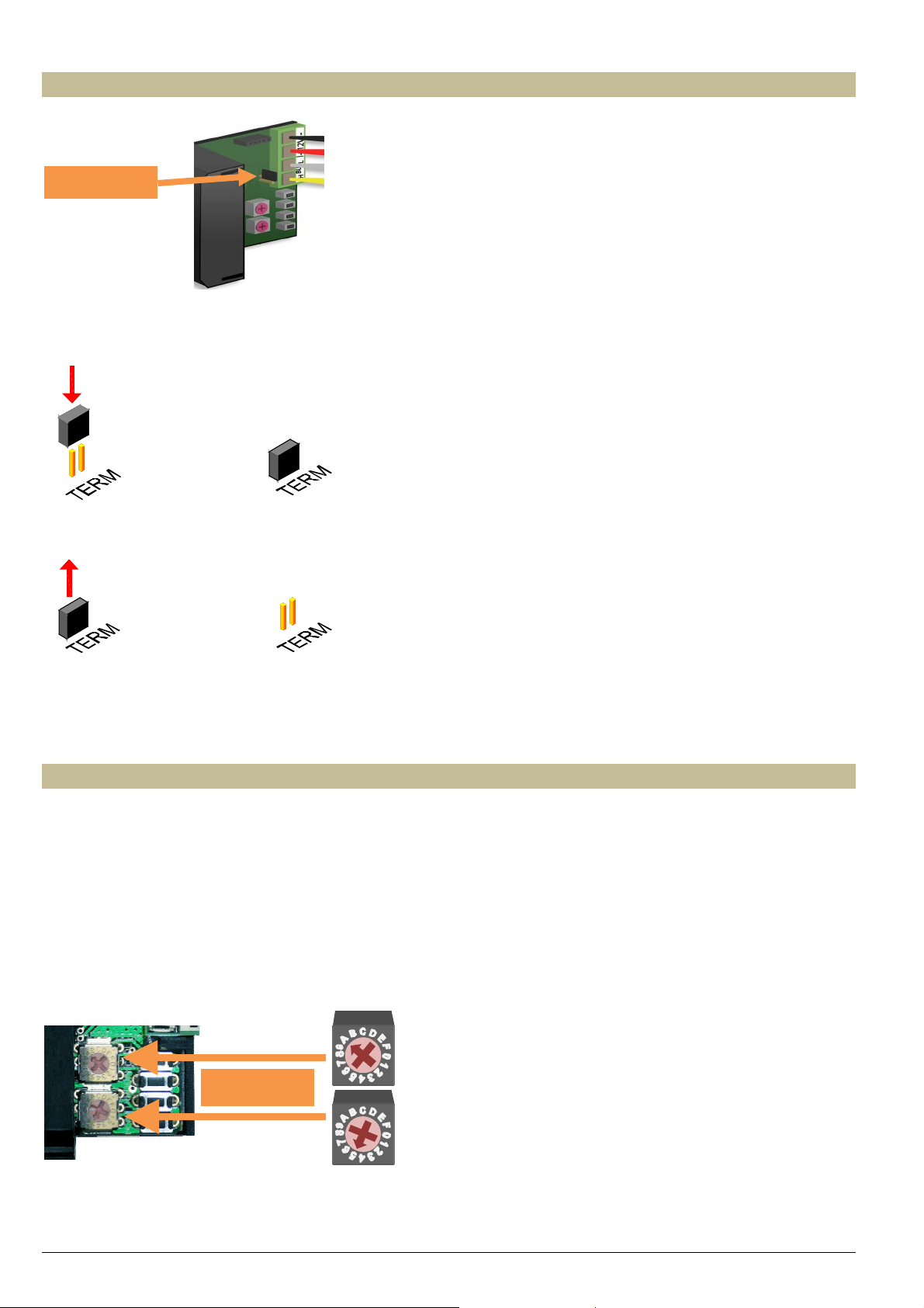
Terminator
Terminator
Normally o nly 2 ‘TERM’ terminators must be used in a complete Velbus installatio n. Usually this will be on one
module inside the distribution box and on the module which is physically located furthest from the distribution box.
On all other modules, the terminator must be removed.
Remark:
In case the wiring contains a lot of branches, still only one terminator is placed on one module inside the distributio n
box and one on the module which is physically located furthest from the distribution box. When communication errors
occur, an additional terminator can be used at the end of another branch. However, the number of terminators should
be limited as more terminators place a heavy load on the bus.
Addressing
Every module on the Velbus system must have its own unique address.
On modules with a rotary switch e.g. the temperature sensor VMB1TS and the relay module VMB4RY the address is
set using the ‘ADDR’ rotary switch (also refer to the manual of the relevant module).
The address of the temperature controller VMB1TC is set via a menu (refer to the manual of the temperature
controller).
These addresses may not be altered afterwards.
Set a unique Velbus address for the temperature using the ‘ADDR’ rotary switches, from ‘00’ to ‘FE’, except the
reserved addresses: ‘81’, ‘91’, ‘A1’, 'B1', ‘C1’, ‘D1’, ‘E1’, ‘F1’ en ‘FF’.
The example below shows the setting for address ‘A5’.
ADDR = A5
VMB1TS manual – edition 2 13
Page 14

LED INDICATION
Anti-freeze, night, day or comfort mode
In rooms that have a temperature sensor VMB1TS the heating (or air-conditioning) can be set in 4 different modes:
comfort, day, night or anti-freeze. Every mode has its own desired temperature setting.
The selected mode is indicated with LEDs.
The sensor module is set to anti-freeze mode when the comfort, day and night mode LEDs are off.
When the comfort, day or night mode LED is flashing, the sensor module is set temporarily (sleep timer) to the
indicated mode and normal program is suspended during that ‘sleep’ time.
Anti-freeze Night Day Comfort
Cooling or heating mode
When the temperature sensor is configured to control an air-conditioning system, the frost flower LED (upper LED)
will be lit.
Setting the heating or cooling mode can only be done through a temperature controller (VMB1TC) or through the
Velbus link program.
Heating mode Cooling mode
Air-conditioner or heater active
When the heater (valve open) or air-conditioner is active, a red LED will be lit.
The red output LED can indicate following error conditions:
Flashing (short on, long off): the heater/cooler should be off but it did not
receive the command from the relays module.
Flashing (short off, long on): the heater/cooler should be on but it did not
receive the command from the relays module.
Fast flashing: configuration of the sensor chip failed.
Note: as long as the error condition exists the output status wil be re-
transmitted every minute.
14 VMB1TS manual – edition 2 – rev.3
Page 15

OPERATION
Pushing the push button repeatedly will switch the module between anti-freeze, night, day or comfort mode
successively.
When the comfort, day or night mode LED is flashing, the sensor module is set temporarily (sleep timer) to the
indicated mode. During this time the program is ignored
When the sleep timer expires, the sensor module will resume the program or in case no program is present will return
to its previous setting.
Remarks:
• Anti-freeze mode can not be set temporarily.
• Standard time is set through the temperature controller.
• Overriding temporary mode can be done by pushing and holding the push button. The LED stops flashing and the
sensor remains in the selected mode until the next program step is executed.
• Local operation can be locked or unlocked via a temperature controller VMB1TC or via the Velbus link program.
• When the sensor module is set to manual mode via a temperature controller VMB1TC or via the Velbus link
program, local operation will be locked.
VMB1TS manual – edition 2 15
Page 16

SETTINGS
Following parameters can be set via the temperature controller (see manual VMB1TC) or via the Velbus link software:
• the zone to which the sensor belongs
• the operating mode (heating or cooling)
• switching the unjam function of the circulation pump and/or heating valve on or off
• the desired comfort temperature for heating
• the desired day temperature for heating
• the desired night temperature for heating
• the anti-freeze safeguard temperature
• the heating limit (upper limit of the heating preset range)
• the temperature difference for fast heating/cooling or for the differential thermostat
• the desired comfort temperature for cooling
• the desired day temperature for cooling
• the desired night temperature for cooling
• the lower limit of the cooling preset range
• the upper limit of the cooling preset range
• the hysteresis
• calibration of the sensor
• the alarm temperatures
• the duration of temporary mode
• the zone number
• the low temperature alarm (alarm when temperature drops below this value)
• the high temperature alarm (alarm when temperature rises above this value)
• the duration of temporary mode: from 1 to 65.279 minutes (45 days, 7 hours, 59 minutes)
• transmitting the current temperature over the Velbus:
o only when requested
o only when changes occur
o at specific time intervals, selectable between 10 and 255 seconds (4 minutes 15 seconds)
• resetting minimum and maximum temperature
• reset time registration for the heater/air-conditioning
• locking or unlocking local control
• the address of the linked sensor to set up a differential thermostat
• sensor name (max. 16 characters)
The cycling protection delay (delay setting is 1 minute) can be modified through the Velbuslink software if the
software version of the sensor module is 0949 or higher (see “Verify software version”).
Preset range
The preset range for the desired temperature can be adjusted by the user.
This is a way to make sure that the heating can never be set higher than a certain value.
Zones
A zone can be useful when the desired temperature of different rooms must follow the same pattern. This way only
one program must be set-up for all rooms that belong to that zone.
Every sensor of that zone must get the same zone number assigned. Up to 7 zones can be defined.
Assigning a zone can be done via the temperature controller (VMB1TC) or through the Velbus link software via a PC
connected to the Velbus PC interface (VMB1USB, VMB1RS of VMBRSUSB).
Protecting the circulation pump and/or heating valves
When a circulation pump or a valve is not being used for some time, it might get stuck. To avoid this, an unjamming
function can be enabled which activates the pump or opens the valve for at least one minute every day.
Enabling of disabling the unjam function can be done via the temperature controller (VMB1TC) or through the Velbus
link software via a PC connected to the Velbus PC interface (VMB1USB, VMB1RS of VMBRSUSB).
16 VMB1TS manual – edition 2 – rev.3
Page 17

A
Time statistics
For every mode (comfort, day, night or anti-freeze) the time during which the heating or air-conditioning was one is
stored.
These statistics can be recalled or reset via the temperature controller (VMB1TC) or through the Velbus link software
via a PC connected to the Velbus PC interface (VMB1USB, VMB1RS of VMBRSUSB).
Minimum and maximum temperature
The sensor records the minimum and maximum temperature.
These values can be examined or reset via the temperature controller (VMB1TC) or through the Velbus link software
via a PC connected to the Velbus PC interface (VMB1USB, VMB1RS of VMBRSUSB).
Differential thermostat
Using two sensors a differential thermostat can be created. When the difference in temperature between both sensors
reaches a certain value, the relay channel can be activated.
To achieve this, the first sensors must know the address of the second one. The second sensor must than be linked
to a relay channel. The temperature difference value is set on the first sensor.
Factory settings
After receiving this module, following factory default settings are already stored into the sensor:
Description Factory default
Zone number No zone
Differential sensor address None
Operating mode Heating
Unjam heating val ve Disabled
Unjam heating valve circulation pump Disabled
Desired comfort temperature for heating 22°C
Desired day temperature for heating 20°C
Desired night temperature for heating 15°C
nti-freeze safeguar d 5°C
Heating limit 30°C
Temperature difference (fast heating/cooling or differential thermostat) 3°C
Calibration factor -2.5°C
Hysteresis 0.5°C
Desired comfort temperature for cooling 21°C
Desired day temperature for cooling 23°C
Desired night temperature for cooling 26°C
Lower limit cooling preset range 16°C
Upper limit cooling preset range 36°C
Low temperature alarm 3°C
High temperature alarm 30°C
Default duration temporary mode (sleep timer) 1 ho ur
Time interval for automatic transmission temperature Disabled
Local control Unlocked
Cycling protection delay 1 minute
VMB1TS manual – edition 2 17
Page 18

CONFIGURING THE OUTPUTS
The sensor module transmit messages over the Velbus when the status of one of its multiple outputs changes. Relay
modules (VMB1RY or VMB4RY) can be linked to these Velbus messages to perform following functions:
• steering the heating valve
• switching the heating or cooling installation to boost mode when the difference in desired and current temperature
is too big
• set the heating boiler in day mode
• steering the air-conditioning
• steering the circulation pump of the heating installation
• generate an alarm when the temperature is too low (heating system down)
• generate an alarm when the temperature is too high (a valve does not close anymore)
Every relay channel that is steered by a temperature sensor must be set to momentary (instant) control. For this, on
the relay module the TIME1 and MODE/TIME2 rotary switches of the channel must be set to position ‘0’.
The easiest way to allocate those relay channels is through the use of the Velbus link software via a PC connected to
a Velbus PC interface (VMB1USB, VMB1RS of VMBRSUSB).
However, it can be done without the use of a computer as described in the following procedures.
18 VMB1TS manual – edition 2 – rev.3
Page 19

Allocate a relay channel to control a valve
When room temperature drops below the desired value, the temperature sensor sends a request on the bus to
energize the relay that opens the valve. When the room temperature rises above the desired value, another request
by the temperature sensor is transmitted over the bus to de-energize the relay thus to close the valve.
In this example, relay channel 1 is used to steer the heating valve.
1. Set the sensor module in anti-freeze mode by
pressing the push button on the front panel
repeatedly until all LEDs are off.
5. Press and hold the lowest push button (HEAT) of
the temperature sensor until the relay is energised
and the red LED on t he sensor module flashes.
2. Set the MODE and TIME1 rotary switches for
channel 1 of relay module to ‘0’ (instant control).
3. Remember the address of this relay module to
reinstate it later on.
4. Set the address of the relay module to ‘C1’.
The ‘MODE 1’ LED flashes to indicate push button
learning mode (PBM).
ADDR.
ADDR.
0
F
E
D
C
B
A
9
8
0
F
E
D
C
B
A
9
8
Learn
Fx
OFF:
Ex
:ON
:
Dx
TGL
Cx
PBM
:
Out1
Mode/
Mode/
Time2
Time2
1
0
1
F
2
2
E
3
3
D
4
4
5
C
5
B
6
6
7
A
7
9
8
Time1
0
1
1
F
2
2
E
3
3
D
4
4
C
5
5
B
6
6
A
7
7
9
8
CH1
x=CH1. ..4
TG1
Bx
TG2::ST2
Ax
Tx
RxON
Mode/
Time2
0
F
E
D
C
B
A
9
Time1
0
F
E
D
C
B
A
9
CH2
9x
8x
1
2
3
4
5
6
7
8
1
2
3
4
5
6
7
8
:
ST1
:
Out2
Mode/
Time 2
1
0
F
2
E
3
D
4
C
5
B
6
A
7
9
8
Time 1
0
1
F
2
E
3
D
4
C
5
B
6
A
7
9
8
CH3 CH4
VMB4RY
ve ll em an
Mode1
Out3 Out4
4 Channel relay module
Mode/
Time1
Time2
1
0
F
0:Moment
2
E
3
1:5s
D
4
C
5
2:10s
B
6
A
7
9
8
3:15s
4:30s
5:1'
Time1
6:2'
0
1
F
2
E
3
7:5'
D
4
C
8:10'
5
B
6
A
7
9:15'
9
8
B:1h
C:2h
D:5h
E:1day
F:Toggle
Mode2
Mode3
Mode/Time2
Start-stop
Staircase
Non-Retrigger
Turn Off D elay
Turn On D elay
Trig Relea se
Blink
5'
10'
15'
30'A:30'
1h
2h
5h
1day
Toggle
Mode4
6. Set the address of the first relay module back to its
original value.
VMB1TS manual – edition 2 19
Page 20

Allocate a relay channel to control the fan (boost)
Some convector types have a built-in fan for fast heating when the current temperature differs too much from the
desired.
In this example the fan is steered by relay channel 2.
1. Set the sensor module in anti-freeze mode by
pressing the push button on the front panel
repeatedly until all LEDs are off.
5. Press and hold the second push button (BOOST)
of the temperature sensor until the relay is
energised and the red LED on the sensor module
flashes.
2. Set the MODE and TIME1 rotary switches for
channel 2 of relay module to ‘0’ (instant control).
3. Remember the address of this relay module to
reinstate it later on.
4. Set the address of the relay module to ‘C2’.
The ‘MODE 2’ LED flashes to indicate push button
learning mode (PBM).
ADDR.
ADDR.
0
F
E
D
C
B
A
9
8
0
F
E
D
C
B
A
9
8
Learn
Fx
OFF:
:ON
Ex
:
Dx
TGL
Cx
PBM
:
Out1
Mode/
Mode/
Time2
Time2
1
0
1
F
2
2
E
3
3
D
4
4
5
C
5
B
6
6
7
A
7
9
8
Time1
0
1
1
F
2
2
E
3
3
D
4
4
C
5
5
B
6
6
A
7
7
9
8
CH1
x=C H1... 4
TG1
Bx
TG2::ST2
Ax
Tx
RxON
Mode/
Time2
F
E
D
C
B
A
9
Time1
F
E
D
C
B
A
9
CH2
9x
8x
1
0
2
3
4
5
6
7
8
0
1
2
3
4
5
6
7
8
:
ST1
:
Out2
Mode/
Time2
1
0
F
2
E
3
D
4
C
5
B
6
A
7
9
8
Time1
0
1
F
2
E
3
D
4
C
5
B
6
A
7
9
8
CH3 CH4
VMB4RY
velleman
Mode1
Out3 Out4
4 Ch annel rela y m odu le
Mode/
Time1
Time2
1
0
F
0:Moment
2
E
3
1:5 s
D
4
C
5
2:10s
B
6
A
7
9
8
3:15s
4:30s
5:1 '
Time1
6:2 '
0
1
F
2
E
3
7:5 '
D
4
C
8:10'
5
B
6
A
7
9:15'
9
8
B:1h
C:2h
D:5h
E:1day
F:Tog gl e
Mode2
Mode3
Mode/Time2
Start-stop
Staircase
Non-Retri gger
Turn Of f Delay
Turn On D el ay
Trig Releas e
Blink
5'
10'
15'
30'A:30'
1h
2h
5h
1day
Toggl e
Mode4
6. Set the address of the relay module back to its
original value.
20 VMB1TS manual – edition 2 – rev.3
Page 21

Allocate a relay channel to set the boiler in day mode
Some heating boilers have a contact input to set them in day or night mode. In night mode, the boiler temperature is
set approximately 10 degrees lower.
The heater boiler must be placed in day mode as soon as one of the sensor modules switches to day or comfort
mode.
In this example, this is done using relay channel 3.
1. Set all sens or modules in anti-freeze mode by
pressing the push button on the front panel
repeatedly until all LEDs are off.
5. Press and hold the third push button (DAY) of the
first temperature sensor until the relay is energised
and the red LED on t he sensor module flashes.
2. Set the MODE and TIME1 rotary switches for
channel 3 of the relay module to ‘0’ (instant
control).
3. Remember the address of this relay module to
reinstate it later on.
4. Set the address of the relay module to ‘C3’. The
‘MODE 3’ LED flashes to indicate push button
learning mode (PBM).
ADDR.
ADDR.
0
F
E
D
C
B
A
9
8
0
F
E
D
C
B
A
9
8
Learn
Fx
OFF:
Ex
:ON
:
Dx
TGL
Cx
PBM
:
Out1
Mode/
Mode/
Time2
Time2
1
0
1
F
2
2
E
3
3
D
4
4
C
5
5
6
B
6
7
A
7
9
8
Time1
0
1
1
F
2
2
3
E
3
D
4
4
C
5
5
B
6
6
7
A
7
9
8
CH1
x=C H1... 4
Bx
TG1
Ax
TG2::ST2
RxON
Tx
Mode/
Time2
F
E
D
C
B
A
9
Time1
F
E
D
C
B
A
9
CH2
9x
1
0
2
3
4
5
6
7
8
0
1
2
3
4
5
6
7
8
:
ST1
:8x
Out2
Mode/
Time2
0
F
E
D
C
B
A
9
8
Time1
0
F
E
D
C
B
A
9
8
CH3 CH4
Mode1
Mode/
Time2
1
2
F
E
3
D
4
C
5
B
6
7
A
Time1
1
F
2
3
E
D
4
C
5
B
6
7
A
VMB4RY
velleman
Mode2
Out3 Out4
4 Ch annel rela y modu le
Time1
1
0
0:Moment
2
3
1:5 s
4
5
2:10s
6
7
9
8
3:15s
4:30s
5:1 '
6:2 '
0
1
2
3
7:5 '
4
8:10'
5
6
9:15'
7
9
8
B:1h
C:2h
D:5h
E:1day
F:Tog gle
Mode3
Mode/Time2
Start-stop
Staircase
Non-Retri gger
Turn Of f D el ay
Turn On D el ay
Trig Releas e
Blink
5'
10'
15'
30'A:30'
1h
2h
5h
1day
Toggl e
Mode4
6. Press and hold the third push button (DAY) of the
second temperature sensor until the relay is
energised and the red LED on the sensor module
flashes.
7. Repeat step 5 for all other sensors.
8. Set the address of the first relay module back to its
original value.
VMB1TS manual – edition 2 21
Page 22

Allocate a relay channel to steer an air-conditioner
The temperature sensor can also be used to control an air-conditioning system. When the sensor is in cooling mode,
the heating will be switched to anti-freeze mode.
When room temperature rises above the desired value, a relay must be energised to switch on the air-conditioner.
When the temperature drops below the desired value the relay must be de-energized to stop cooling.
In this example relay channel 4 is used to steer the air-conditioner.
1. Set the sensor module in anti-freeze mode by
pressing the push button on the front panel
repeatedly until all LEDs are off.
5. Press and hold the upper push button (COOL) of
the temperature sensor until the relay is energised
and the red LED on t he sensor module flashes.
2. Set the MODE and TIME1 rotary switches for
channel 4 of the relay module to ‘0’ (instant
control).
3. Remember the address of this relay module to
reinstate it later on.
4. Set the address of the relay module to ‘C4’. The
‘MODE 4’ LED flashes to indicate push button
learning mode (PBM).
ADDR.
ADDR.
0
F
E
D
C
B
A
9
8
0
F
E
D
C
B
A
9
8
Learn
Fx
OFF:
Ex
:ON
:
Dx
TGL
Cx
PBM
:
Out1
Mode/
Mode/
Time2
Time2
1
0
1
F
2
2
E
3
3
D
4
4
5
C
5
B
6
6
A
7
7
9
8
Time1
1
1
0
F
2
2
E
3
3
D
4
4
5
C
5
B
6
6
A
7
7
9
8
CH1
x=CH1 ...4
Bx
TG1
Ax
TG2::ST2
Tx
RxON
Mode/
Time 2
0
F
E
D
C
B
A
9
Time 1
0
F
E
D
C
B
A
9
CH2
9x
1
2
3
4
5
6
7
8
1
2
3
4
5
6
7
8
:
ST1
:8x
Out2
Mode/
Time2
1
0
F
E
D
C
B
A
9
8
Time1
0
1
F
E
D
C
B
A
9
8
CH3 CH4
Mode1
Mode/
Time2
0
F
2
E
3
D
4
5
C
B
6
A
7
9
8
Time1
0
F
2
E
3
D
4
5
C
B
6
A
7
9
8
VMB4RY
velleman
Mode2
Out3 Out4
4 Channel relay module
Mode/Time2
Time1
1
2
3
4
5
6
7
1
2
3
4
5
6
7
0:Moment
1:5s
2:10s
3:15s
4:30s
5:1'
6:2'
7:5'
8:10'
9:15'
B:1h
C:2h
D:5h
E:1day
F:Toggle
Start-stop
Staircase
Non-Retrigger
Turn Off De lay
Turn On Delay
Trig Re lease
Blink
5'
10'
15'
30'A:30'
1h
2h
5h
1day
Toggle
Mode3
Mode4
6. Set the address of the relay module back to its
original value.
7. The sensor module must be placed in cooling
mode via the temperature controller VMB1TC or
through the Velbus link software. The upper LED
(ice crystal) must be lit.
22 VMB1TS manual – edition 2 – rev.3
Page 23

Allocate a relay channel for the circulation pump
Some valves have a contact that closes when the valve is open. By wiring all the contacts in parallel, the circulation
pump can be steered.
For valves that do not have these contacts, a relay can be assigned to the temperature sensors to steer the
circulation pump.
In this example the pump must be active as soon as one of the sensor modules indicates heating is required. This can
be done e.g. through relay channel 1 of a relay module.
1. Set all sens or modules in anti-freeze mode by
pressing the push button on the front panel
repeatedly until all LEDs are off.
5. Press and hold the pushbutton on the front panel of
the first sensor module and simultaneously press
and hold the lowest push button (HEAT) until the
relay is energised and the red LED on the sensor
module flashes. First release the lowest push
button (HEAT) followed by the push button on the
front panel.
2. Set the MODE and TIME1 rotary switches for
channel 1 of the relay module to ‘0’ (instant
control).
3. Remember the address of this relay module to
reinstate it later on.
4. Set the address of the relay module to ‘C1’. The
‘MODE 1’ LED flashes to indicate push button
learning mode (PBM).
ADDR.
ADDR.
0
F
E
D
C
B
A
9
8
0
F
E
D
C
B
A
9
8
Learn
Fx
OFF:
Ex
:ON
:
Dx
TGL
Cx
PBM
:
Out1
Mode/
Mode/
Time2
Time2
1
0
1
F
2
2
E
3
3
D
4
4
C
5
5
6
B
6
7
A
7
9
8
Time1
0
1
1
F
2
2
3
E
3
D
4
4
C
5
5
B
6
6
7
A
7
9
8
CH1
x=CH1...4
Bx
TG1
Ax
TG2::ST2
RxON
Tx
Mode/
Time2
F
E
D
C
B
A
9
Time1
F
E
D
C
B
A
9
CH2
9x
1
0
2
3
4
5
6
7
8
0
1
2
3
4
5
6
7
8
:
ST1
:8x
Out2
Mode/
Time2
0
F
E
D
C
B
A
9
8
Time1
0
F
E
D
C
B
A
9
8
CH3 CH4
Mode1
Mode/
Time2
1
2
F
E
3
D
4
C
5
B
6
7
A
Time1
1
F
2
3
E
D
4
C
5
B
6
7
A
VMB4RY
velleman
Mode2
Out3 Out4
4 Ch annel rela y m odu le
Time1
1
0
0:Moment
2
3
1:5 s
4
5
2:10s
6
7
9
8
3:15s
4:30s
5:1 '
6:2 '
0
1
2
3
7:5 '
4
5
8:10'
6
7
9:15'
9
8
B:1h
C:2h
D:5h
E:1day
F:Tog gle
Mode3
Mode/Time2
Start-stop
Staircase
Non-Retri gger
Turn Of f D el ay
Turn On D el ay
Trig Releas e
Blink
5'
10'
15'
30'A:30'
1h
2h
5h
1day
Toggl e
Mode4
6. Press and hold the pushbutton on the front panel of
the second sensor module and simultaneously
press and hold the lowest push button (HEAT) until
the relay is energised and the red LED on the
sensor module flashes. First release the lowest
push button (HEAT) followed by the push button on
the front panel.
7. Repeat step 5 for all other sensors.
8. Set the address of the relay module back to its
original value.
VMB1TS manual – edition 2
23
Page 24

Allocate a relay channel for the low temperature alarm
The sensor module contains an anti-freeze protection, but when the heating system is down it is still possible that the
temperature in a room drops. To warn the user that the room temperature reaches freezing point a relay can be
energised. This relay channel can be used e.g. to switch on a control light or an electrical heater.
As an example relay channel 2 of a relay module is used.
1. Set the sensor module in anti-freeze mode by
pressing the push button on the front panel
repeatedly until all LEDs are off.
5. Press and hold the pushbutton on the front panel of
the sensor module and simultaneously press and
hold the second push button (BOOST) until the
relay is energised and the red LED on the sensor
module flashes. First release the second push
button (BOOST) followed by the push button on the
front panel.
2. Set the MODE and TIME1 rotary switches for
channel 2 of the relay module to ‘0’ (instant
control).
3. Remember the address of this relay module to
reinstate it later on.
4. Set the address of the relay module to ‘C2’. The
‘MODE 2’ LED flashes to indicate push button
learning mode (PBM).
ADDR.
ADDR.
0
F
E
D
C
B
A
9
8
0
F
E
D
C
B
A
9
8
Learn
Fx
OFF:
Ex
:ON
:
Dx
TGL
Cx
PBM
:
Out1
Mode/
Mode/
Time2
Time2
1
0
1
F
2
2
E
3
3
D
4
4
C
5
5
6
B
6
7
A
7
9
8
Time1
0
1
1
F
2
2
3
E
3
D
4
4
C
5
5
B
6
6
7
A
7
9
8
CH1
x=CH1...4
Bx
TG1
Ax
TG2::ST2
RxON
Tx
Mode/
Time2
F
E
D
C
B
A
9
Time1
F
E
D
C
B
A
9
CH2
9x
1
0
2
3
4
5
6
7
8
0
1
2
3
4
5
6
7
8
:
ST1
:8x
Out2
Mode/
Time2
0
F
E
D
C
B
A
9
8
Time1
0
F
E
D
C
B
A
9
8
CH3 CH4
Mode1
Mode/
Time2
1
2
F
E
3
D
4
C
5
B
6
7
A
Time1
1
F
2
3
E
D
4
C
5
B
6
7
A
VMB4RY
velleman
Mode2
Out3 Out4
4 Ch annel rela y m odu le
Time1
1
0
0:Moment
2
3
1:5 s
4
5
2:10s
6
7
9
8
3:15s
4:30s
5:1 '
6:2 '
0
1
2
3
7:5 '
4
5
8:10'
6
7
9:15'
9
8
B:1h
C:2h
D:5h
E:1day
F:Tog gle
Mode3
Mode/Time2
Start-stop
Staircase
Non-Retri gger
Turn Of f D el ay
Turn On D el ay
Trig Releas e
Blink
5'
10'
15'
30'A:30'
1h
2h
5h
1day
Toggl e
Mode4
6. Set the address of the relay module back to its
original value.
24 VMB1TS manual – edition 2
Page 25

Allocate a relay channel for the high temperature alarm
The sensor module can also control a relay when room temperature should reach extreme high values. This situation
might occur when a heating valve is broken e.g. it does not close anymore causing the room to keep heating up. The
relay contact can than be used e.g. to switch on a warning light or activate an audible warning signal.
As an example, relay channel 3 of a relay module is used.
1. Set the sensor module in anti-freeze mode by
pressing the push button on the front panel
repeatedly until all LEDs are off.
5. Press and hold the pushbutton on the front panel of
the sensor module and simultaneously press and
hold the third push button (DAY) until the relay is
energised and the red LED on the sensor module
flashes. First release the third push button (DAY)
followed by the push button on t he front panel.
2. Set the MODE and TIME1 rotary switches for
channel 3 of the relay module to ‘0’ (instant
control).
3. Remember the address of this relay module to
reinstate it later on.
4. Set the address of the relay module to ‘C3’. The
‘MODE 3’ LED flashes to indicate push button
learning mode (PBM).
ADDR.
ADDR.
0
F
E
D
C
B
A
9
8
0
F
E
D
C
B
A
9
8
Learn
Fx
OFF:
:ON
Ex
:
Dx
TGL
Cx
PBM
:
Out1
Mode/
Mode/
Time2
Time2
1
0
1
F
2
2
3
E
3
D
4
4
C
5
5
B
6
6
7
A
7
9
8
Time1
0
1
1
2
F
2
E
3
3
D
4
4
C
5
5
6
B
6
7
A
7
9
8
CH1
x=CH1...4
TG1
Bx
TG2::ST2
Ax
RxON
Tx
Mode/
Time2
0
F
E
D
C
B
A
9
Time1
0
F
E
D
C
B
A
9
CH2
9x
1
8
1
8
:
:8x
7
7
ST1
2
3
4
5
6
2
3
4
5
6
Out2
Mode/
Time2
0
F
E
D
C
B
A
9
8
Time1
0
F
E
D
C
B
A
9
8
CH3 CH4
Mode1
Mode/
Time2
1
F
2
E
3
D
4
C
5
B
6
7
A
Time1
1
2
F
E
3
D
4
C
5
6
B
7
A
VMB4RY
velleman
Mode2
Out3 Ou t4
4 Channel relay module
Time1
1
0
0:Moment
2
3
1:5s
4
5
2:10s
6
7
9
8
3:15s
4:30s
5:1'
6:2'
0
1
2
3
7:5'
4
5
8:10'
6
7
9:15'
9
8
B:1h
C:2h
D:5h
E:1day
F:Toggle
Mode3
Mode/Time2
Start-stop
Staircase
Non-Retrigger
Turn Off De lay
Turn On Delay
Trig Release
Blink
5'
10'
15'
30'A:30'
1h
2h
5h
1day
Toggle
Mode4
6. Set the address of the relay module back to its
original value.
VMB1TS manual – edition 2
25
Page 26

Ad
dre
REMOTE CONTROL
The sensor module can be operated locally, but also remotely via a temperature controller VMB1TC (refer to the
manual of the controller).
The sensor module can also be operated remotely by connecting pushbuttons to the Velbus.
Pushbuttons can be defined for:
• setting the sensor module mode to comfort
• setting the sensor module mode to day
• setting the sensor module mode to night
• setting the sensor module mode to anti-freeze
• setting the sensor module mode to heating
• setting the sensor module mode to cooling
• lock the local operation of the sensor module
• unlock the local operation of the sensor module
For every operating function up to 10 different pushbuttons can be assigned.
The easiest way to assign those pushbuttons is by using the Velbus link software using a PC t hat is connected to a
Velbus PC interface (VMB1USB, VMB1RS of VMBRSUSB).
However, it can be done without using a PC.
Always remember the address of the sensor module to reinstate it later on.
Set the address of the sensor module to the function for which pushbuttons will be assigned.
ss
learning
mode
Flashing indication LEDs Function
F1
E1
D1
C1
B1
A1
91
81
Pushbuttons that put the sensor module in
comfort mode
Pushbuttons that put the sensor module in day
mode
Pushbuttons that put the sensor module in
night mode
Pushbuttons that put the sensor module in
anti-freeze mode
Pushbuttons that put the sensor module in
heating mode
Pushbuttons that put the sensor module in
cooling mode
Pushbuttons that lock the local operation of
the sensor module
Pushbuttons that unlock the local operation of
the sensor module
Adding a pushbutton is done by pressing on it until its indication LED flashes.
If this fails, the maximum number of pushbuttons is reached.
When finished, reinstate the original address of the sensor module.
26 VMB1TS manual – edition 2
Page 27

In the example below we use a control panel VMB4PD of which 8 controls are linked to a temperature sensor.
The labels on the display are assigned as indicated (refer to the manual of the VMB4PD):
Comfort Day
Night Anti-freeze
The labels on the display for the second page are assigned as indicated:
Heating Lock
Cooling Unlock
Remotely control comfort mode
With the upper left button of the control panel the temperature sensor is set to comfort mode.
1. Remember the address of the sensor module to
reinstate it later.
2. Set the address of the sens or module to ‘F1’.
The comfort and day LEDs are flashing to indicate
learning mode for pushbuttons that place the
module in comfort mode.
3. Press and hold the ‘Comfort’ pushbutton
(at least 1 second) until its indication LED starts
flashing.
Comfort Day
Night Anti-freeze
ADDR = F1
Remark:
When multip le sensor modules needs to react to
the same pushbutton, remember their addresses
and set them also to ‘F1’.
Remark:
As long as the pushbutton is pressed, the LEDs on
the sensor module will be off. This to confirm that
the pushbutton is assigned.
VMB1TS manual – edition 2
4. Repeat step 3 in case other pus hbuttons must set
the sensor module in comfort mode.
5. Reinstate the address of the sensor module(s) to
its (their) original value.
27
Page 28

Remotely control day mode
With the upper right button of the control panel the temperature sensor is set to day mode.
1. Remember the address of the sensor module to
reinstate it later.
2. Set the address of the sens or module to ‘E1’.
The day LED is flashing to indicate learning mode
for pushbuttons that place the module in day mode.
ADDR = E1
Remark:
When multip le sensor modules needs to react to
the same pushbutton, remember their addresses
and set them also to ‘E1’.
3. Press and hold the ‘day’ pushbutton
(at least 1 second) until its indication LED starts
flashing.
Comfort Day
Night Anti-freeze
Remark:
As long as the pushbutton is pressed, the LEDs on
the sensor module will be off. This to confirm that
the pushbutton is assigned.
4. Repeat step 3 in case other pus hbuttons must set
the sensor module in day mode.
5. Reinstate the address of the sensor module(s) to
its (their) original value.
28 VMB1TS manual – edition 2
Page 29

Remotely control night mode
With the lower left button of the control panel the temperature sensor is set to night mode.
1. Remember the address of the sensor module to
reinstate it later.
2. Set the address of the sens or module to ‘D1’.
The night LED is flashing to indicate learning mode
for pushbuttons that place the module in night
mode.
3. Press and hold the ‘night’ pushbutton
(at least 1 second) until its indication LED starts
flashing.
Comfort Day
Night Anti-freeze
ADDR = D1
Remark:
When multip le sensor modules needs to react to
the same pushbutton, remember their addresses
and set them also to ‘D1’.
Remark:
As long as the pushbutton is pressed, the LEDs on
the sensor module will be off. This to confirm that
the pushbutton is assigned.
4. Repeat step 3 in case other pus hbuttons must set
the sensor module in night mode.
5. Reinstate the address of the sensor module(s) to
its (their) original value.
VMB1TS manual – edition 2
29
Page 30

Remotely control anti-freeze mode
With the lower right button of the control panel the temperature sensor is set to anti-freeze mode.
1. Remember the address of the sensor module to
reinstate it later.
2. Set the address of the sens or module to ‘C1’.
The day, night and comfort LEDs are flashing to
indicate learning mode for pushbuttons that place
the module in anti-freeze mode.
3. Press and hold t he ‘anti-freeze’ pushbutton
(at least 1 second) until its indication LED starts
flashing.
Comfort Day
Night Anti-freeze
ADDR = C1
Remark:
When multip le sensor modules needs to react to
the same pushbutton, remember their addresses
and set them also to ‘C1’.
Remark:
As long as the pushbutton is pressed, the LEDs on
the sensor module will be off. This to confirm that
the pushbutton is assigned.
4. Repeat step 3 in case other pus hbuttons must set
the sensor module in anti-freeze mode.
5. Reinstate the address of the sensor module(s) to
its (their) original value.
30 VMB1TS manual – edition 2
Page 31

Remotely set heating mode
With the upper left button on the second page of the control panel the temperature sensor is set in heating mode.
1. Remember the address of the sensor module to
reinstate it later.
2. Set the address of the sens or module to ‘B1’.
The heating LED flashes to indicate learning mode
for pushbuttons that place the module in heating
mode.
ADDR = B1
Remark:
When multip le sensor modules needs to react to
the same pushbutton, remember their addresses
and set them also to ‘B1’.
3. Select the second page of the control panel by
pressing the small pushbutton.
Heating Lock
Cooling Unlock
4. Press and hold the ‘Heating’ pushbutton
(at least 1 second) until its indication LED starts
flashing.
Heating Lock
Cooling Unlock
Remark:
As long as the pushbutton is pressed, the LEDs on
the sensor module will be off. This to confirm that
the pushbutton is assigned.
5. Repeat step 4 in case other pus hbuttons must set
the sensor module in heating mode.
6. Reinstate the address of the sensor module(s) to
its (their) original value.
VMB1TS manual – edition 2
31
Page 32

Remotely set cooling mode
With the lower left button on the second page of the control panel the temperature sensor is set in cooling mode.
1. Remember the address of the sensor module to
reinstate it later.
2. Set the address of the sens or module to ‘A1’.
The cooling mode LED flashes to indicate learning
mode for pushbuttons that place the module in
cooling mode.
4. Press and hold the ‘Cooling’ pushbutton
(at least 1 second) until its indication LED starts
flashing.
Heating Lock
Cooling Unlock
ADDR = A1
Remark:
When multip le sensor modules needs to react to
the same pushbutton, remember their addresses
and set them also to ‘A1’.
3. Select the second page of the control panel by
pressing the small pushbutton.
Heating Lock
Cooling Unlock
Remark:
As long as the pushbutton is pressed, the LEDs on
the sensor module will be off. This to confirm that
the pushbutton is assigned.
5. Repeat step 4 in case other pus hbuttons must set
the sensor module in cooling mode.
6. Reinstate the address of the sensor module(s) to
its (their) original value.
32 VMB1TS manual – edition 2
Page 33

Remotely lock local operation
With the upper right button on t he second page of the control panel locally operating the temperature sensor can be
disabled.
1. Remember the address of the sensor module to
reinstate it later.
2. Set the address of the sens or module to ‘91’.
All LEDs are flashing to indicate learning mode for
pushbuttons that lock local operation.
ADDR = 91
Remark:
When multiple sensor modules need to react to the
same pushbutton, remember their addresses and
set them also to ‘91’.
3. Select the second page of the control panel by
pressing the small pushbutton.
Heating Lock
Cooling Unlock
4. Press and hold the ‘Lock’ pushbutton
(at least 1 second) until its indication LED starts
flashing.
Heating Lock
Cooling Unlock
Remark:
As long as the pushbutton is pressed, the LEDs on
the sensor module will be off. This to confirm that
the pushbutton is assigned.
5. Repeat step 4 in case other pus hbuttons must
disable local operation of the sensor.
6. Reinstate the address of the sensor module(s) to
its (their) original value.
VMB1TS manual – edition 2
33
Page 34

Remotely unlock local operation
With the lower right button on the second page of the control panel locally operating the temperature sensor can be
enabled.
1. Remember the address of the sensor module to
reinstate it later.
2. Set the address of the sens or module to ‘81’.
The cooling, comfort, day and night LEDs are
flashing to indicate learning mode for pushbuttons
that unlock local operation.
4. Press and hold the ‘Unlock’ pushbutton
(at least 1 second) until its indication LED starts
flashing.
Warm Vergrendel
Koel Ontgrendel
ADDR = 81
Remark:
When multiple sensor modules need to react to the
same pushbutton, remember their addresses and
set them also to ‘81’.
3. Select the second page of the control panel by
pressing the small pushbutton.
Heating Lock
Cooling Unlock
Remark:
As long as the pushbutton is pressed, the LEDs on
the sensor module will be off. This to confirm that
the pushbutton is assigned.
5. Repeat step 4 in case other pus hbuttons must
enable local operation of the sensor.
6. Reinstate the address of the sensor module(s) to
its (their) original value.
34 VMB1TS manual – edition 2
Page 35

A
ddre
Deleting an assigned pushbutton
Always remember the address of the sensor module to reinstate it later on.
Set the address of the sensor module to the function for which pushbuttons must be deleted.
ss
learning
mode
Flashing indication LEDs Function
F1
E1
D1
C1
B1
A1
91
81
Pushbuttons that put the sensor
module in comfort mode
Pushbuttons that put the sensor
module in day mode
Pushbuttons that put the sensor
module in night mode
Pushbuttons that put the sensor
module in anti-freeze mode
Pushbuttons that put the sensor
module in heating mode
Pushbuttons that put the sensor
module in cooling mode
Pushbuttons that lock the local
operation of the sensor module
Pushbuttons that unlock the local
operation of the sensor module
The indication LEDs of the pushbuttons that are assigned to the selected function will flash.
Deleting an assigned pushbutton is done by pressing it until its indication LED switches off.
When finished, reinstate the original address of the sensor module.
VMB1TS manual – edition 2
35
Page 36

A
d
A
Deleting all assigned pushbuttons for a certain function
Always remember the address of the sensor module to reinstate it later on.
Set the address of the sensor module to the function for which pushbuttons must be deleted.
dress
learning
mode
F1
E1
D1
C1
B1
1
91
81
The indication LEDs of the pushbuttons that are assigned to the selected function will flash.
Deleting all pushbutton assigned to the selected function is done by pressing the pushbutton on the front panel of the
sensor module until all LEDs are off.
Flashing indication LEDs Function
Pushbuttons that put the sensor
module in comfort mode
Pushbuttons that put the sensor
module in day mode
Pushbuttons that put the sensor
module in night mode
Pushbuttons that put the sensor
module in anti-freeze mode
Pushbuttons that put the sensor
module in heating mode
Pushbuttons that put the sensor
module in cooling mode
Pushbuttons that lock the local
operation of the sensor module
Pushbuttons that unlock the local
operation of the sensor module
Set ADDR to delete function (see
tabel above)
1 sec
When releasing the pushbutton the indication LEDs of all the assigned pushbuttons will t urn off and the LEDs o n the
sensor module start flashing.
When finished, reinstate the original address of the sensor module.
36 VMB1TS manual – edition 2
Page 37

Deleting all assigned pushbuttons
Always remember the address of the sensor module to reinstate it later on.
Set the address of the sensor module to ‘F1’. the comfort and day LED are flashing.
Deleting all assigned pushbuttons for all functions at once is done by pressing the mode pushbutton on the sensor
module for about 10 seconds.
The indication LEDs on the sensor mod ule will first switch off and about 7 seconds later will start flashing to confirm
the deleting operation.
ADDR = F1
10 sec
When finished, reinstate the original address of the sensor module.
VMB1TS manual – edition 2
37
Page 38

SWITCHING TO ANTI FREEZE MODE THROUGH WINDOW CONTACTS
The heating can be switched automatically in anti freeze mode as soon as a window featuring window contacts is
opened.
The LEDs will switch off on the VMB1 TS temperature sensor. The VMB1TC temperature controller displays an anti
freeze and key symbol together with a blinking mode LED.
Locatie
5
Badkamer
0m 18
-
↑
Mode
←
Menu
→
↓
The heating cannot be set into another mode as long as a window remains open.
Once all windows closed, the heating will swit h to the initial mode.
The used contacts may be of the NO or the NC type, and may be connected to a VMB8PB push-button interface or a
VMB6IN input module.
You can connect maximum 10 NO and 10 NC contacts to the sensor module.
Assign the contacts through Velbuslink software and a PC connected the Velbus interface (VMB1USB, VMB1RS or
VMBRSUSB).
The NC contacts (i.e. contacts closed when window is closed) must be connected to the “Normal closed disable
switch” function of the sensor module.
The NO contacts (i.e. contacs open when the window is closed) must be connected to the “Nor mal open disable
switch” function of the sensor module.
Remark:
This function is only available on a sensor module with software version 0949 or higher (see “Verify software version”
in this user manual).
38 VMB1TS manual – edition 2
Page 39

DIFFERENTIAL THERMOSTAT
Using two sensors, a differential thermostat can be created. When the temperature difference between both sensor s
crosses a preset value, a relay channel can be activated.
To achieve this, the first sensors must know the address of the second one. The second sensor must than be linked
to a relay channel. The temperature difference value is set on the first sensor.
The settings can be done via a temperature controller VMB1TC or via the Velbus link program.
Schematic overview differential thermostat (sensor2 in heating mode):
SENSOR1
Set-up:
Differential sensor address =
address sensor2
Temp. Difference ∆t = -10°...10°
SENSOR2
Set-up:
heating
t1
Measured temp t1 + ∆t
Schematic overview differential thermostat (sensor2 in cooling mode):
SENSOR1
Set-up:
Differential sensor address =
address sensor2
Temp. Difference ∆t = -10°...10°
t2
= Desired temperature for sensor2
Remark:
if t1+ ∆t > t
(mode2 = anti-freeze, night, day or comfort)
SENSOR2
heating on when t1+ ∆t > t2
than desired temp. sensor2 = t
mode2
Set-up:
cooling
mode2
t1
Measured temp t1 + ∆t
Refer to some applications of a differential thermostat below.
VMB1TS manual – edition 2
t2
= Desired temperature for sensor2
Remark:
if t1+ ∆t < t
(mode2 = anti-freeze, night, day or comfort)
Cooler on when t1+ ∆t < t2
than desired temp. sensor2 = t
mode2
mode2
39
Page 40

The passage automatically 3° cooler than the office
When the sensor module in the office is set to day-mode, the temperature in the passage must be 3° lower than t he
office. Is the day temperature of the office is set to 20°C the desired passage temperature will be 17°C.
When the sensor module in the office is set to night-mode, the temperature in the passage must be 3° lower than t he
office. Is the night temperature of the office is set to 15°C the desired passage temperature will be 12°C.
Office Passage
Configuration:
The easiest way to configure the system is to use the Velbus link program via a PC connected on the Velbus PC
interface (VMB1USB, VMB1RS of VMBRSUSB).
However, configuration can also be done without the aid of a computer. Refer to the procedure below.
1. Link the heating output of the office sensor to a relay channel.
2. Use the relay channel to control the valve of the office radiator.
3. Link the heating output of the passage sensor to another relay channel.
4. Use this relay channel to control the valve of the passage radiator
5. On the temperature controller, select the office sensor.
6. Go to the extended menu.
7. Scroll to the sensor setup menu and select it.
8. Scroll to the ‘diff. sensor’ submenu and select it.
9. Choose the passage sensor and confirm.
10. Scroll to the ‘Temp. diff.’ submenu and select it.
11. Set the temperature difference to -3° and confirm.
12. Quit the menu.
The configuration is now finished and the differential thermostat is enabled.
Remarks:
• Make sure both sensors are in heating mode (frost flower LED on the sensor is off).
• The passage temperature can never be higher than the preferred setting of its selected mode (anti-freeze, night,
day or comfort).
40 VMB1TS manual – edition 2
Page 41

Passive cooling of a bedroom
During summer time the bedroom is cooled via a fan that extracts air from a cooler room.
Mount a temperature sensor in both rooms. The temperature sensor of the bedroom is set to cooling mode and the
cooling output is linked to a relay channel that controls the fan.
When the temperature in the cooler room is about 3 degrees lower than the bedroom temperature the fan is activated.
Cooler room
Bedroom
Configuration:
The easiest way to configure the system is to use the Velbus link program via a PC connected on the Velbus PC
interface (VMB1USB, VMB1RS of VMBRSUSB).
However, configuration can also be done without the aid of a computer. Refer to the procedure below.
1. Link the cooling output of the bedroom sensor to a relay channel.
2. Use the relay channel to control the fan.
3. On the temperature controller, select the sensor of the coolest room.
4. Go to the extended menu.
5. Scroll to the sensor setup menu and select it.
6. Scroll to the ‘diff. sensor’ submenu and select it.
7. Choose the bedroom sensor and confirm.
8. Scroll to the ‘Temp. diff.’ submenu and select it.
9. Set the temperature difference to 3° and confirm.
10. Quit the menu.
11. Select the bedroom sensor on the temperature controller
12. Go to the extended menu.
13. Scroll to the sensor setup menu and select it.
14. Select the operating mode submenu.
15. Set it to cooling and confirm.
16. Quit the menu.
The configuration is now finished and the differential thermostat is enabled.
Remark:
The cooling will stop when t he bedroom temperature reaches the preferred setting of its selected mode (anti-freeze,
night, day or comfort).
VMB1TS manual – edition 2
41
Page 42

VERIFY SOFTWARE VERSION
The software version can be verified via the Velbus link software.
Check on http://www.velbus.eu whether you have the latest version. If a newer version is available, download it.
Connect the Velbus interface to a PC and run the upgrade-software and follow the instructions on the screen.
Remark:
Upgrading a module is not without risk. Do not interrupt the process!
If for any reason the upgrade should fail, the module will cease normal operatio n. T he module will have to be returned
to the manufacturer.
42 VMB1TS manual – edition 2
Page 43

Refer to our website for more information: www.velbus.be
VMB1TS manual – edition 2
43
 Loading...