

Page 1
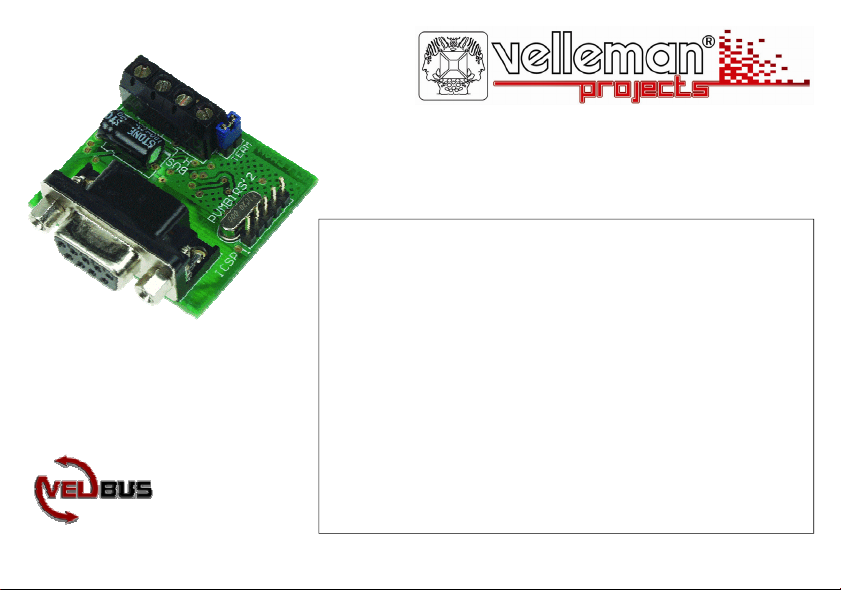
Serial interface
VMB1RS
can be used to control the VELBUS system through a computer
VELBUS message processing on the computer
full duplex RS232C communication with PC
galvanic separation between the computer and the VELBUS system
LED indication for:
power voltage
data reception and forwarding to the computer
data reception and forwarding through VELBUS
RS232 :
Reception buffer for 6 commands.
Report when reception buffer is full and free for reception.
Bus fault and ‘bus active’ status report.
required power supply: 12VDC
consumption: 10mA
Page 2
1
9
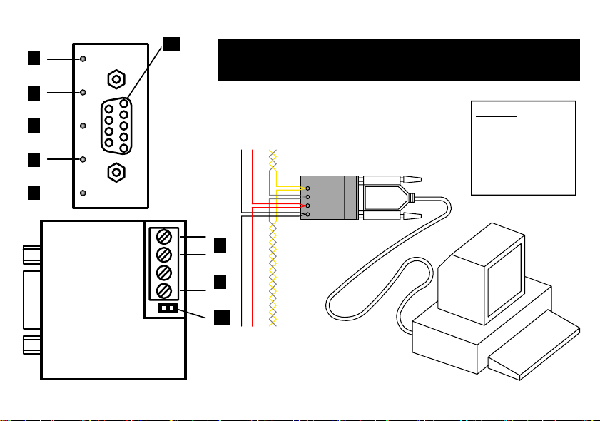
CONNECTION EXAMPLE - AANSLUITVOORBEELD -
EXAMPLES DE CONNEXION - ANSCHLUSSBEISPIELE -
EJEMPLO DE CONEXIÓN
2
RS232C :
3
Baud rate : 38400
Data bits : 8
4
VMB1RS
5
LH
-
6
+
L
7
H
8
-12V+ BUS
TWISTED
(0.5mm )
H
BUS
L
+
12V
9-POLE SUBD
-
PAIR
2
To COM-Port
Page 3
1. Velbus forward LED
2. Velbus reception LED
3. RS232C forward LED
4. RS232C reception LED
5. Velbus power LED
6. 12V power supply
7. Velbus
8. Termination
9. Connection to the computer’s serial port
1. Velbus zend-LED
2. Velbus ontvangst-LED
3. RS232C zend-LED
4. RS232C ontvangst-LED
5. Velbus voedings-LED
6. 12V voeding
7. Velbus
8. Afsluiting
9. Verbinding naar de seriële poort van de computer
1. LED de transfert du velbus
2. LED de réception du velbus
3. LED de transfert de l’RS232C
4. LED de réception de l’RS232C
5. LED d’alimentation du velbus
6. Alimentation 12V
7. Velbus
8. Terminaison
9. Connexion vers le port sériel de l’ordinateur
1. Velbus-Sende-LED
UK
2. Velbus- Empfangs-LED
3. RS232C Sende-LED
4. RS232C Empfangs-LED
5. Velbus Stromversorgungs-LED
6. 12V-Stromversorgung
7. Velbus
8. Abschlusswiderstand
9. Verbindung zum seriellen Port des Computers
1. LED de transmisión del velbus
NL
2. LED de recepción del velbus
3. LED de transmisión de RS232C
4. LED de recepción de RS232C
5. LED de alimentación del velbus
6. Alimentación 12V
7. Velbus
8. Terminación
9. Conexión al puerto en serie del ordenador
FR
D
ES
3
Page 4
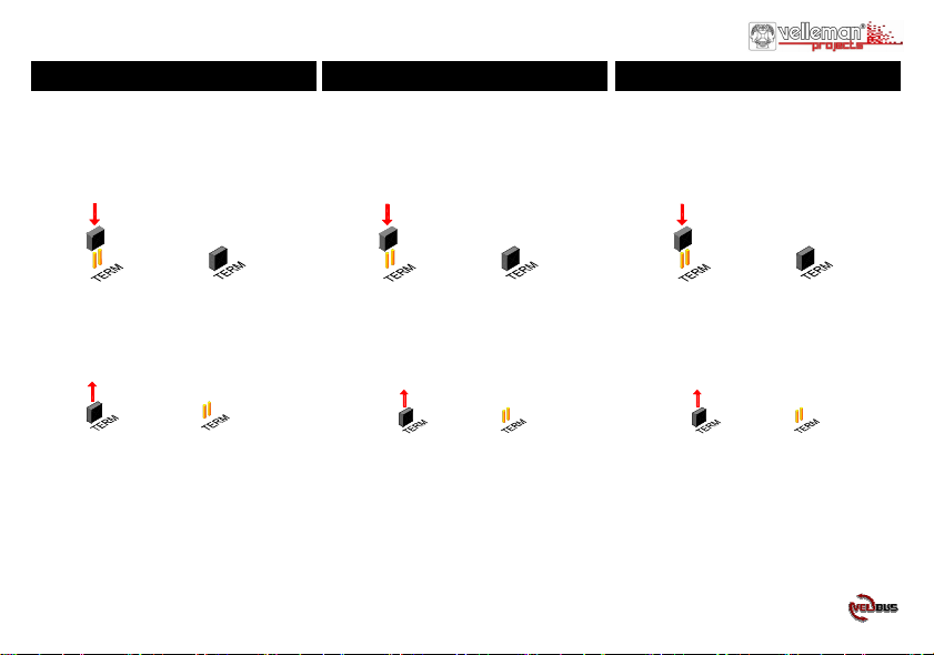
TERMINATION AFSLUITING TERMINAISON
If the module is connected at the start or end
of a cable on the VELBUS, place the
‘TERM’ jumper.
Remove the jumper in all other cases.
If different cable wiring topologies (tree,
star, loop, ...) are used, place a jumper on the
end module of the longest cable only, NOT
on each end point.
4
Indien de module op het begin of het einde van
de VELBUS-kabel aangesloten is, moet de
‘TERM’ jumper geplaatst worden.
In alle andere gevallen moet deze verwijderd
worden.
Indien de bekabeling in ster- of
boomstructuur uitgevoerd is, wordt er enkel
een afsluiter geplaatst op de module die aan
het beginpunt van de kabel aangesloten is en
op de module die op het uiteinde van de
langste kabel aangesloten is.
Placez le cavalier TERM uniquement dans
un module connecté au début ou en fin de
connexion Velbus.
Effacez le cavalier dans tous les autres
modules.
Placez uniquement un cavalier sur le dernier
module du câble le PLUS LONG et non sur
tous les modules lorsque vous utilisez
différents modèles de câblage (arbre, étoile
boucle…).
Page 5

VERSCHLUSS
Montieren Sie die TERM-Steckbrücke bei
einem Modul am Anfang oder am Ende des
Velbus-Anschlusses.
Entfernen Sie die Steckbrücke bei allen
anderen Modulen.
Verwenden Sie verschiedene
Verdrahtungsausführungen (Baum, Stern,
Schleife…), verbinden Sie dann nur eine
Steckbrücke mit dem letzten Modul des
längsten Kabels und NICHT mit jedem
Modul
TERMINACIÓN
Ponga el jumper TERM sólo en un módulo
conectada al principio o al extremo de
conexión Velbus.
Borre el jumper en todos los otros módulos.
Ponga sólo un jumper
en el último módulo del cable MÁS LARGO
y no en todos los módulos si utiliza
diferentes modelos de cableado (árbol,
estrella, bucle…).
5
Page 6

CONNECTION
For connection between the modules, use twisted pair cable (ex.
EIB 2x2x0.8mm2, UTP 8x0.51mm - CAT5 or other). Use minimum 0.5mm² cable. For long wiring (>50m) or if a lot of modules
( > 10) are connected to one wire, use 1mm² cable. Connect the 1218Vdc (mind the polarity) and connect the bus wires (mind the
polarity).
Connect the module to a COM port of the computer. You may use
a Velleman serial cable, type CW014.
Remark:
The serial computer connection is electrically separated from the
VELBUS and the 12V power cable via an optical link.
If the module is connected as the final device on the VELBUS,
place the ‘TERM’ jumper. Remove the jumper in all other cases.
6
AANSLUITING
Om de modules met elkaar te verbinden gebruikt men best een
twisted-pair kabel (EIB 2x2x0.8mm2, UTP 8x0.51mm - CAT5 of
gelijkwaardig). Indien er veel modules (meer dan 10) op de kabel
aangesloten zijn of bij zeer lange leidingen (langer dan 50m) is het
belangrijk om de draaddoorsnede voldoende dik te voorzien
(0.5mm2 of meer). Verbind de 12V tot 18V gelijkspanning (let op
de polariteit) met de module. Sluit de bus aan (let op de polariteit)
op de module.
Verbind de module met een COM-poort van de computer. U kunt
hiervoor de seriële kabel van Velleman type CW014 gebruiken.
Opmerking:
De seriële computerverbinding is elektrisch gescheiden van de
VELBUS en de 12V voedingskabel via een optische link.
Indien de module als laatste op de VELBUS aangesloten is, moet de
‘TERM’ jumper geplaatst worden. In alle andere gevallen moet deze
verwijderd worden.
Page 7

CONNEXION
Utilisez un câble torsadé (UTP ou autre) pour interconnecter les
modules. Utilisez un câble avec un diamètre minimal de 0.5mm².
Utilisez un câble avec un diamètre de 1mm² pour les longues
connexions (> 50m) ou lorsque la connexion comporte une
multitude élevée de modules (> 10).
Connectez le 12-18VCC (respectez la polarité) et le câblage du bus
(respectez la polarité).
Connectez le module au port COM de l’ordinateur. Utilisez un
câble sériel Velleman type CW014.
Remarque:
La connexion sérielle est électriquement séparée du VELBUS et le
cordon d’alimentation 12V par un lien optique.
Si le module est connecté comme dernier appareil dans la série
VELBUS, il faut placer le pontage ‘TERM’. Retirez-le si ceci n’est
pas le cas.
ANSCHLUSS
Verbinden Sie die 12V bis 18V Gleichspannung (achten Sie auf die
Polarität) mit dem Modul. Bei sehr langen Leitungen ist es wichtig,
dass der Drahtdurchmesser ausreichend dick ist (1mm2). Schließen
Sie den Bus an das Modul an (achten Sie auf die Polarität).
Verwenden Sie dazu eine verdrillte Leitung mit einem
Durchmesser von 0.5mm2 oder mehr bei sehr langen Leitungen.
Verbinden Sie das Modul mit einem COM-Port des Computers. Sie
können hierzu ein serielles Kabel des Velleman-Typs CW014
verwenden.
Bemerkung:
Die serielle Computerverbindung ist elektrisch vom VELBUS und
dem 12V-Stromversorgungskabel getrennt über einen optischen
Link.
Wenn das Modul als letztes an das VELBUS-System
angeschlossen ist, muss der ‘TERM’ Jumper installiert werden. In
allen anderen Fällen soll er entfernt werden.
7
Page 8

CONEXIÓN
Utilice un cable trenzado (EIB 2x2x0.8mm2, UTP 8x0.51mm CAT5 u otro) para interconectar los módulos. Utilice un cable con
un diámetro mín. de 0.5mm². Utilice un cable con un diámetro de
1mm² para conexiones largas (> 50m) o si están conectados
muchos módulos (> 10) a un cable. Conecte 12-18VDC (respete la
polaridad) y el cableado del bus (respete la polaridad).
Conecte el módulo al puerto COM del ordenador. Utilice un cable
serie del tipo Velleman CW014.
Nota:
La conexión serie está separada de manera eléctrica del VELBUS y
el cable de alimentación 12V por una conexión óptica.
Si el módulo está conectado como último aparato en la serie
VELBUS, ponga el puente ‘TERM’. Quítelo si no es el caso.
8
Page 9

USE
Connect the module to the VELBUS system and the computer (see
Connexion).
Run a computer programme allowing you to communicate with the
VELBUS system. You can also write a programme of your own.
When powering the module, a ‘Bus active’ and ‘Reception ready’
message will be sent to the computer.
All messages appearing on the VELBUS system will also be sent
serially to the computer.
Valid commands generated by the computer will be sent to the
module via the COM port.
These commands are placed on the VELBUS system through the
serial interface module.
When an excessive amount of commands have been sent in one
time, the reception buffer will be filled. This will be reported to the
computer. The computer programme must interrupt the forwarding
and wait for a ‘Reception ready’ message to be able to offer new
commands.
If the commands can not be placed correctly on the VELBUS, a
bus error will occur and will be forwarded tot the computer. The
serial interface module will auto-restart after 25 seconds and erase
the reception buffer.
GEBRUIK
Verbind de module met het VELBUS-systeem en de computer (zie
aansluitingen).
Op de computer moet men een programma draaien dat toelaat met
het VELBUS-systeem te communiceren. Men kan hiervoor ook
zelf een programma ontwikkelen.
Bij het onder spanning komen van de module wordt een ‘Bus
actief’ en ‘Ontvangst klaar’ boodschap naar de computer verstuurd.
Alle boodschappen die nu op het VELBUS-systeem verschijnen,
worden eveneens serieel verstuurd naar de computer.
Geldige commando’s gegenereerd door de computer worden via de
COM-poort naar de module verstuurd.
Deze commando’s worden door de seriële interface-module op het
VELBUS-systeem geplaatst.
Indien er teveel commando’s ineens verstuurd worden, zal de
ontvangstbuffer vol lopen en wordt dit gemeld aan de computer.
Het computerprogramma moet nu het verzenden onderbreken en
wachten op een ‘ontvangst klaar’ bericht om terug nieuwe
commando’s te kunnen aanbieden.
Als de commando’s niet correct op de VELBUS geplaatst kunnen
worden, zal er een busfout optreden en doorgegeven worden naar
de computer. Na 25 seconden zal de seriële interface-module
zichzelf herstarten en de ontvangstbuffer wissen.
9
Page 10

EMPLOI
Connectez le module au système VELBUS et l’ordinateur (voir
Connexion).
Lancez un logiciel sur l’ordinateur vous permettant de
communiquer avec le système VELBUS. Il est possible d’écrire
son propre logiciel.
En branchant la tension sur le module, un message ‘Bus activé’ et
‘Réception terminée’ est envoyé vers l’ordinateur.
Chaque message apparaissant sur le système VELBUS sera
également envoyé vers l’ordinateur.
Les commandes valides générées par l’ordinateur seront envoyées
vers le module par le port COM.
Ces commandes sont placées sur le système VELBUS par le
module d’interface sérielle.
Si on envoi une quantité trop élevée de commandes en une fois, le
tampon récepteur se remplit. Ceci sera communiqué à l’ordinateur.
Le logiciel coupera l’envoi et attendra un message ‘Réception
terminé’ pour qu’il puisse offrir de nouvelles commandes.
Si les commandes ne peuvent pas être placées sur le VELBUS de
manière correcte, une erreur de bus apparaîtra et sera transmis à
l’ordinateur. Après un délai de 25 secondes, le module d’interface
sérielle se relancera et effacera le tampon récepteur.
10
ANWENDUNG
Verbinden Sie das Modul mit dem VELBUS-System und dem
Computer (siehe Schaltplan).
Auf dem Computer soll man ein Programm, das mit dem
VELBUS-System kommunizieren kann, ablaufen lassen. Sie
können auch selbst ein Programm entwickeln.
Beim Einschalten des Moduls wird eine 'Bus aktiv’ und ‘Empfang
fertig’-Meldung an den Computer geschickt.
Alle Nachrichten, die jetzt auf dem VELBUS-System erscheinen,
werden auch seriell an den Computer geschickt.
Gültige Befehle, die vom Computer ignoriert werden, werden über
den COM-Port an das Modul geschickt. Diese Befehle werden
durch eine serielle Schnittstelle auf das VELBUS-System
übertragen.
Wenn zuviele Befehle zur gleichen Zeit verschickt werden, wird
der Empfangsspeicher voll geraten und wird das an den Computer
gemeldet. Das Computerprogramm muss jetzt das Versenden
unterbrechen und auf eine ‘Empfang fertig’-Meldung warten um
neue Befehle anbieten zu können.
Wenn die Befehle nicht korrekt an das VELBUS-System
übertragen werden können, wird ein Busfehler auftreten und wird
er an den Computer weitergeleitet werden. Nach 25 Sekunden wird
sich das serielle Schnittstellenmodul neu starten und den
Empfangsspeicher löschen.
Page 11

USO
Conecte el módulo al sistema VELBUS y al ordenador (véase
Conexión).
Ejecute un software en el ordenador que permite comunicar con el
sistema VELBUS. Es posible escribir su propio software.
Un mensaje ‘Bus activo’ y ‘Recepción terminada’ se envía al
ordenador al activar el módulo.
Cada mensaje que aparece en el sistema VELBUS se enviará
también al ordenador.
Los mandos válidos generados por el ordenador se enviarán al
módulo por el puerto COM.
Los mandos se ponen en el sistema VELBUS por el módulo de
interface serie.
Si se envía demasiados mandos a la vez, el tampón receptor se
llenará. Esto se comunicará al ordenador. El software interrumpirá
el envío y esperará hasta que reciba el mensaje ‘Recepción
terminada’ antes de poder ofrecer nuevos mandos.
Si no es posible poner los mandos en el VELBUS de manera
correcta, une error de bus aparecerá y se transmitirá al ordenador.
Después de 25 segundos, el módulo de interface serie se reactivará
y borrará el tampón receptor.
11
Page 12

VELLEMAN Components NV
Legen Heirweg 33
9890 Gavere
Belgium Europe
www.velleman.be
www.velleman-kit.com
www.velbus.be
Modifications and typographical errors reserved - © Velleman Components nv.
HVMB1RS - 2006 - ED1_rev2
5 410329 347093
 Loading...