

Page 1

D
E
L
1
B
M
V
V
V
PWM LED strip dimmer module
for the Velbus system
M
M
B
B
1
1
L
L
E
E
D
D
Page 2

CONTENTS
CONTENTS .................................................................................................................... 2
DESCRIPTION ................................................................................................................ 3
CHARACTERISTICS ...................................................................................................... 3
VELBUS CHARACTERISTICS ...................................................................................... 5
OVERVIEW ..................................................................................................................... 6
LED INDICATION ........................................................................................................... 7
USE WITHOUT VELBUS ................................................................................................ 8
Wiring diagram for 12V LED strips .............................................................................. 8
Wiring diagram for 24V LED strips .............................................................................. 9
Addressing ................................................................................................................. 10
Setting the operating mode ........................................................................................ 11
USE WITH A VELBUS SYSTEM .................................................................................. 14
Wiring diagram for 12V LED strips ............................................................................ 14
Wiring diagram for 24V LED strips ............................................................................ 16
Addressing ................................................................................................................. 17
Terminator ................................................................................................................. 18
Operation ................................................................................................................... 19
Linking switch-off pushbuttons ............................................................................... 21
Linking switch-on pushbuttons ............................................................................... 22
Linking switch-on/off pushbuttons .......................................................................... 23
Linking dimming pushbuttons ................................................................................. 24
Linking pushbuttons to increase brightness ........................................................... 25
Linking pushbuttons to decrease brightness .......................................................... 26
Creating atmospheres ............................................................................................ 27
Set all atmospheres to maximum brightness ......................................................... 29
Deleting assigned pushbuttons .............................................................................. 30
Deleting assigned pushbuttons for a certain function ............................................. 31
Deleting all assigned pushbuttons ......................................................................... 32
Setting the operating mode ........................................................................................ 33
Software version verification ...................................................................................... 36
VMB1LED PWM LED strip dimmer Manual– edition 1_rev.2
2
Page 3

DESCRIPTION
LED illumination is getting more popular. By dimming the output of the LED strips (12V or 24V series) an
attractive atmosphere can be created. A dimmer module is placed between the external LED power supply and
the LED strip.
The use of Pulse Width Modulation (PWM) greatly reduces heat development inside the dimmer module
compared to linear regulators.
CHARACTERISTICS
Dimmer:
• Suitable for dimming 12 or 24V LED strips or low voltage lamps.
• Can also be used to regulate the speed of DC motors (10 to 30V)
• Not suitable for LED lamps with built-in driving electronics
• Maximum consumption: 5A (60W@12V or 150W@30V)
• High efficiency by using PWM
• PWM frequency: ca. 100Hz
• Gradually switching on and off (ca. 1.5s)
• Dimming from 0 to 100% in ca. 4 seconds
• Short-circuit proof
• Thermal protected
• Protected against wrongly connected power supply by a 20A fuse
• Required external power supply: 10 to 30Vdc / 5A
• Power supply dimmer galvanically separated from the Velbus power supply
Operating modes (selectable through the ‘MODE’ rotary switch):
• instant control
• Start/stop timer
• staircase lighting timer
• dimmer
• dimmer with memory
• multiple positions dimmer
• gradually-on dimmer
• gradually-off dimmer
• gradually on/off dimmer
Time settings (adjustable through the ‘TIME’ rotary switch):
• switch-off time (or dimming speed when gradually on/off dimming
• 16 possible time settings: instant - 5s - 10s - 15s - 30s - 1min - 2 min - 5min - 10min - 15min - 30min - 1u - 2u
- 5u - 1dag – on/off
Control:
• by placing multiple pushbuttons in parallel
• de-chattering of the pushbutton input: 65ms
• local control on the module
• through Velbus instructions or through pushbuttons connected to the Velbus system
• Operating functions:
o by pushbuttons that switch the LEDs on (full brightness)
o by pushbuttons that switch off the LEDs
o by pushbuttons that switch the LEDs on (full brightness) or off
o by pushbuttons that activate the selected mode on the module
o by pushbuttons that make the LEDs shine more bright
o by pushbuttons that make the LEDs shine less bright
o by pushbuttons that create a atmosphere
o by slider controls that turn on the LEDs with the desired brightness
VMB1LED PWM LED strip dimmer Manual– edition 1_rev.2
3
Page 4

Led indications:
• to show the dim position (0...100%)
• to indicate the activated mode:
o continue on: desired dim position reached
o slow flash: the timer is running
o fast flash: the dim position is changing
o very fast flash: the module is in learning mode to assign pushbuttons
o 2x short flash: a communication error occurred
• when power is supplied
• to send the status of the de dimmer to the control modules
• when receiving or transmitting data over the Velbus
Configuration:
• 247 possible addresses (selectable via the ‘ADDR’ rotary switches)
• storage capacity for 12 different pushbuttons per control function
• configurable via the Velbus pc interface (VMB1USB, VMB1RS of VMBRSUSB) en the Velbus link software
• also configurable without using a PC by operating the desired pushbuttons in learning mode
• learned pushbuttons are memorized during power cuts
Power supply module:
• required power supply: 10...30VDC
• consumption in standby: 25mA @ 30VDC (20mA 2 16VDC)
• maximum consumption: 60mA @ 30VDC
Dimensions:
• standard DIN-rail housing: 2 modules wide
• length x depth x height: 90 x 36 x 58mm
VMB1LED PWM LED strip dimmer Manual– edition 1_rev.2
4
Page 5

VELBUS CHARACTERISTICS
• 2-wire communication for Velbus data and 2 wires for power supply
• data transmission: 16.6 Kbit/s
• Serial data protocol: CAN (Controller Area Network)
• Short circuit proof (towards negative or positive pole of the power supply)
• bus error indication: 2 short flashes of the LEDs
• auto recovering after 25 seconds when a bus error occurs
The dimmer module can be given a designation with a maximum of 16 characters.
The dimmer module can transmit following messages:
• dimmer status
• local pushbutton status
• dimmer type LED (including software version)
• dimmer name
• local pushbutton name
• the communication error counter
• memory content
The dimmer module can transmit following instructions:
• to change the status of the LEDs on a pushbutton module
• to switch off the LEDs on a pushbutton module
• to switch on the LEDs on a pushbutton module
• to make the LEDs on a pushbutton module flash slowly
• to make the LEDs on a pushbutton module flash fast
• to make the LEDs on a pushbutton module flash very fast
The dimmer module can receive following messages:
• the status of a pushbutton module
• the status of a slider control
The dimmer module can receive following instructions:
• set the dimming value
• start timer
• request dimmer status
• inquire module type and software version
• read the communication error counter
• request dimmer name and local push button name
• request memory content
• overwrite memory content
• switch off pushbutton indication LED
VMB1LED PWM LED strip dimmer Manual– edition 1_rev.2
5
Page 6

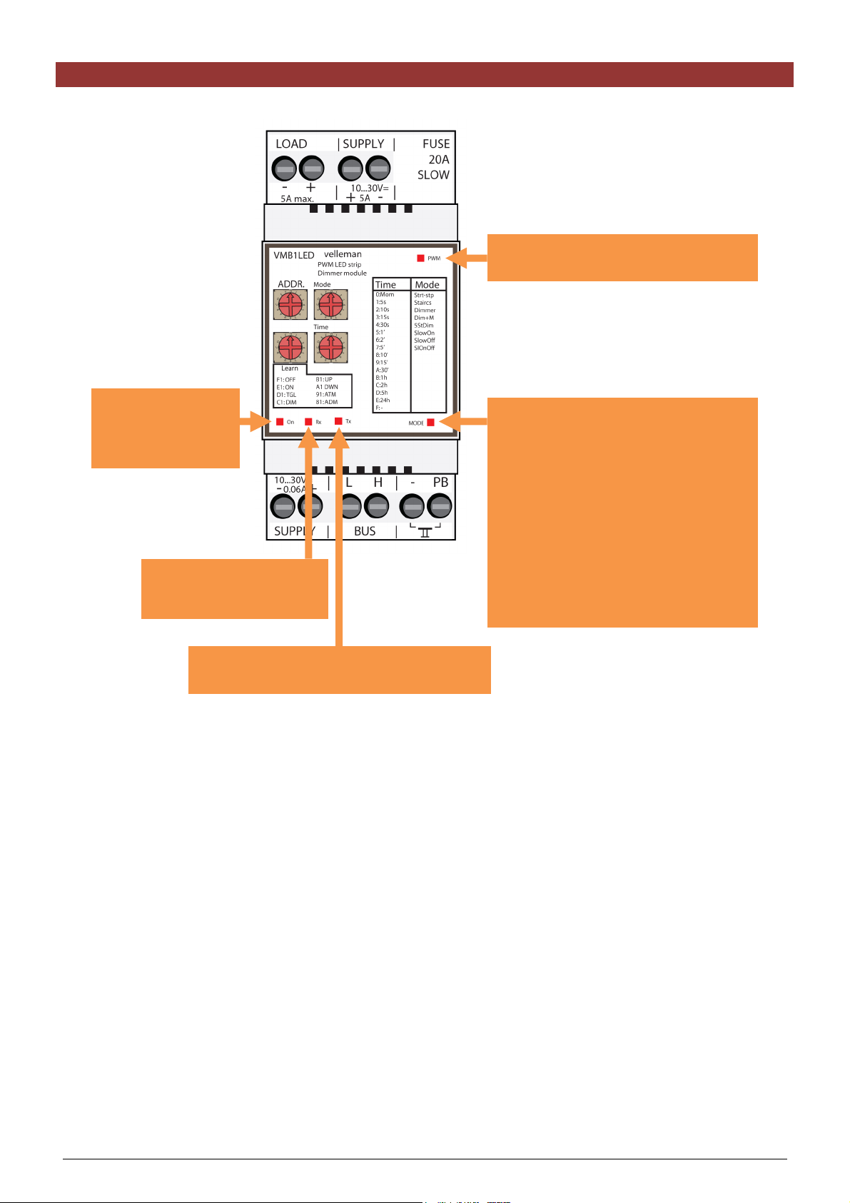
OVERVIEW
1
2
13
7
6
8
9
12
10 11
3 4 5
Wiring
LED strip
1
LED strip power supply
2
Module or Velbus power supply
3
Velbus
4
Pushbutton
5
Settings
Address
6
Mode
7
Time
8
Power supply
9
Receiving Velbus data
10
Sending Velbus data
11
Operating mode
12
Dim position (0 ~ 100%)
13
LED indication
VMB1LED PWM LED strip dimmer Manual– edition 1_rev.2
6
Page 7
LED INDICATION
PWM LED:
brightness indication for dim position
On LED:
on when input
power supply is
present
Rx LED:
on when receiving Velbus
data
Mode LED:
• off when LED strip is off
• on when LED strip lit with steady
brightness
• flashes fast while brighness of LED
strip changes
• flashes slow when switch-off delay
is active
• flashes very fast when dimmer
module is in learning mode
• flashes 2x short upon detecting a
communication error
Tx LED:
on when transmitting Velbus data
VMB1LED PWM LED strip dimmer Manual– edition 1_rev.2
7
Page 8
USE WITHOUT VELBUS
The dimmer module can be used in combination with a direct current power supply (12 or 24V) to dim LED strips
(12 or 24V).
The function of the connected pushbuttons is set via the ‘Mode’ rotary switch.
The switch-off time (or dim time in slowly on/off dimmer mode) is set via the ‘Time’ rotary switch.
The address must be set to ‘00’ to disable communication with the Velbus system.
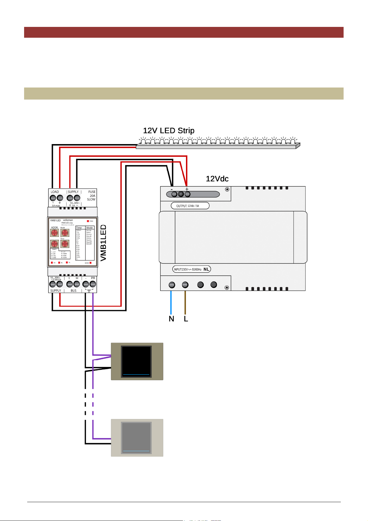
Wiring diagram for 12V LED strips
Use a 12V direct current power supply for the LED strips.
power supply
pushbutton
pushbutton
VMB1LED PWM LED strip dimmer Manual– edition 1_rev.2
8
Page 9
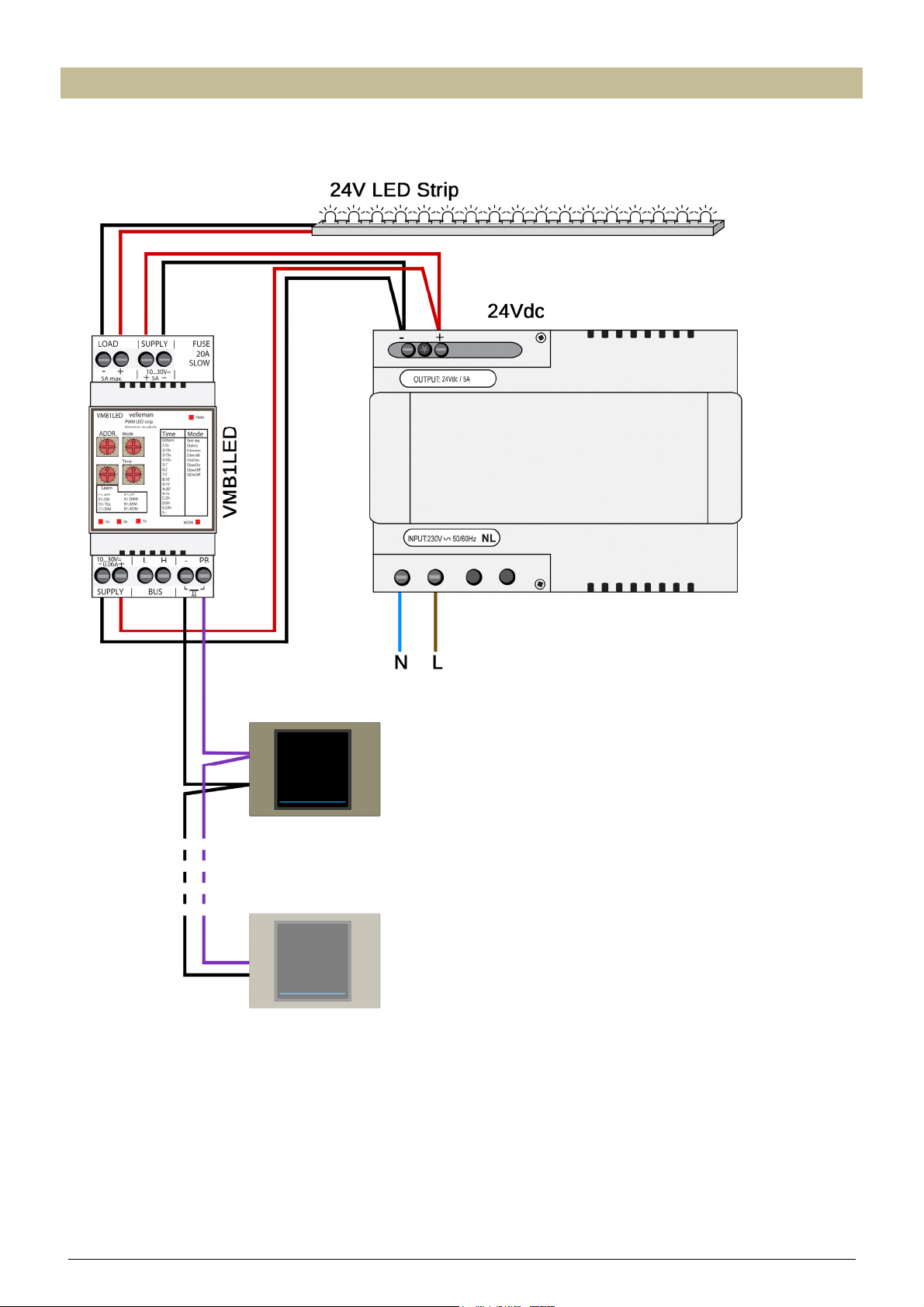
Wiring diagram for 24V LED strips
Use a 24V direct current power supply for the LED strips.
power supply
pushbutton
pushbutton
VMB1LED PWM LED strip dimmer Manual– edition 1_rev.2
9
Page 10
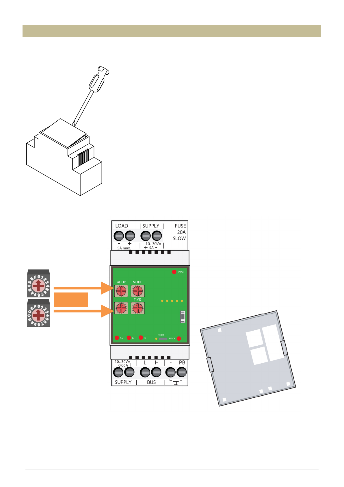
Addressing
When the Velbus is not used, the address must be set to ‘00’ to disable communication with the Velbus system.
Remove the cover.
Set both ‘ADDR’ rotary switches to ‘0’.
ADDR = 00
VMB1LED PWM LED strip dimmer Manual– edition 1_rev.2
10
Page 11
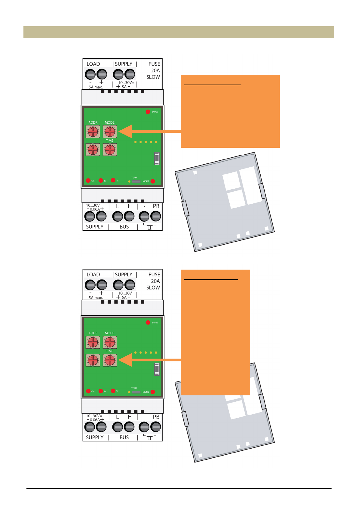
Setting the operating mode
The function of the pushbuttons is determined by the position of the ‘Mode’ and ‘Time’ rotary switches.
MODE rotary switch
0 : start/stop timer
1 : staircase lighting timer
2 : dimmer
3 : dimmer with memory function
4 : multiple position dimmer
5 : slowly on dimmer
6 : slowly off dimmer
7 : slowly on/off dimmer
TIME rotary switch
0 : instant control
1 : 5 seconds
2 : 10 seconds
3 : 15 seconds
4 : 30 seconds
5 : 1 minute
6 : 2 minutes
7 : 5 minutes
8 : 10 minutes
9 : 15 minutes
A : 30 minutes
B : 1 hour
C : 2 hours
D : 5 hours
E : 24 hours
F : -
VMB1LED PWM LED strip dimmer Manual– edition 1_rev.2
11
Page 12

Depending on the setting of the ‘MODE’ rotary switch the dimmer module will act as follows:
MODE Operating mode Description
0 Start/stop timer Pushing the pushbutton will switch on the LED strip. When
the set time (see ‘TIME’ switch) expires the LED strip is
switched off.
Pushing the pushbutton while the LED strip is already on
will switch it off immediately.
1 Staircase lighting timer Pushing the pushbutton will switch on the LED strip. When
the set time (see ‘TIME’ switch) expires the LED strip
brightness will slowly diminish to be completely off after 30
seconds.
Pushing the pushbutton while the LED strip is already on
will restart the timer.
Dimmer A short push will switch on the LED strip (full brightness).
2
Another short push when the LED strip is already on will
switch it off.
Push and hold will dim the LED strip up to maximum or
down to minimum brightness. The next push will dim in the
opposite direction When the set time (see ‘TIME’ switch)
expires the LED strip is switched off.
3 Dimmer with memory function A short push will switch on the LED strip (brightness as
memorized since last use). Another short push when the
LED strip is already on will switch it off.
Push and hold will dim the LED strip up to maximum or
down to minimum brightness. The next push will dim in the
opposite direction.
When the set time (see ‘TIME’ switch) expires the LED strip
is switched off.
4 Multiple position dimmer Pushing the pushbutton will switch on the LED strip (full
brightness). Every next push within 5 seconds after the
previous will change brightness by 25%.
When the LED strip is on and the previous push occurred
more than 5 seconds earlier, a push will switch off the LED
strip.
When the set time (see ‘TIME’ switch) expires the LED strip
is switched off.
5 Slowly on dimmer Pushing the pushbutton will slowly turn on the LED strip to
full brightness. The duration to achieve maximum
brightness is determined by the ‘TIME’ switch.
Pushing the pushbutton while the LED strip is already on
will switch it off immediately.
6 Slowly off dimmer Pushing the pushbutton will switch on the LED strip to full
brightness.
Pushing the pushbutton when the LED strip is on will slowly
decrease brightness until the LED strip is off. The duration
to switch the LED strip to off is determined by the ‘TIME’
switch.
Pushing the pushbutton during decreasing brightness will
turn the LED strip back to full brightness.
7 Slowly on/off dimmer Pushing the pushbutton will slowly turn on the LED strip to
full brightness.
Pushing the pushbutton when the LED strip is on will slowly
decrease brightness until the LED strip is off.
The duration to achieve maximum brightness or to switch
the LED strip off is determined by the ‘TIME’ switch.
Remarks:
When the ‘TIME’ rotary switch is set to ‘0’ the dimmer module will always work in instant control, no matter what
operating mode is set. On other words, the LED strip will light up as soon as the pushbutton is pushed.
When the ‘TIME’ rotary switch is set to ‘F’ the dimmer module will not automatically switch off or the dimming speed
will be maximal when the module is set to slowly on, slowly off or slowly on/off mode.
VMB1LED PWM LED strip dimmer Manual– edition 1_rev.2
12
Page 13

Depending on the ‘TIME’ rotary switch the time will be set as follows:
TIME Description
0 Instant control (the LED strip lights up as soon as the pushbutton is pushed)
1 5 seconds switch-off time or 5 seconds dimming time in slowly on/off dim mode
2 10 seconds switch-off time or 10 seconds dimming time in slowly on/off dim mode
3 15 seconds switch-off time or 15 seconds dimming time in slowly on/off dim mode
4 30 seconds switch-off time or 30 seconds dimming time in slowly on/off dim mode
5 1 minute switch-off time or 1 minute dimming time in slowly on/off dim mode
6 2 minutes switch-off time or 2 minutes dimming time in slowly on/off dim mode
7 5 minutes switch-off time or 5 minutes dimming time in slowly on/off dim mode
8 10 minutes switch-off time or 10 minutes dimming time in slowly on/off dim mode
9 15 minutes switch-off time or 15 minutes dimming time in slowly on/off dim mode
A 30 minutes switch-off time or 30 minutes dimming time in slowly on/off dim mode
B 1 hour switch-off time or 1 hour dimming time in slowly on/off dim mode
C 2 hours switch-off time or 2 hours dimming time in slowly on/off dim mode
D 5 hours switch-off time or 5 hours dimming time in slowly on/off dim mode
E 24 hours switch-off time or 24 hours dimming time in slowly on/off dim mode
F No switch-off time or maximal dimming speed in slowly on/off dim mode
VMB1LED PWM LED strip dimmer Manual– edition 1_rev.2
13
Page 14

USE WITH A VELBUS SYSTEM
The dimmer module can be part of a Velbus system and controlled by a control panel (VMB4PD) or using
pushbuttons connected to a pushbutton interface (VMB8PB).
To interconnect the Velbus modules the use of twisted-pair cable (EIB 2x2x0.8mm2, UTP 8x0.51mm - CAT5 or
equivalent) is recommended.
When a lot of modules (more than 10) are connected to the cable or longer cable lengths (more than 50m) are
used, it is important to use a cable with appropriate diameter (0.5mm² or higher).
Connect the bus to the module (beware of the polarity).
Connect the 12V to 18V direct current to the module (beware of the polarity).
A 12 or 24V direct current power supply is required for the LED strips. That power supply is completely separated
from the Velbus power supply. When connecting, make sure to use the correct polarity, as using the wrong
polarity will melt the internal fuse. The fuse can be replaced by removing the plastic power supply terminal guard.
Wiring diagram for 12V LED strips
Use a 12V direct current power supply for the LED strips.
power supply
VMB1LED PWM LED strip dimmer Manual– edition 1_rev.2
14
Page 15

It is also possible to use the Velbus in combination with pushbuttons that are directly connected to the pushbutton
input of the dimmer module.
The function of the directly connected pushbuttons is set via the ‘Mode’ and ‘Time’ rotary switches.
power supply
pushbutton
pushbutton
VMB1LED PWM LED strip dimmer Manual– edition 1_rev.2
15
Page 16

Wiring diagram for 24V LED strips
Use a 24V direct current power supply for the LED strips.
power supply
A combination of the Velbus with directly connected pushbuttons is also possible.
power supply
pushbutton
pushbutton
VMB1LED PWM LED strip dimmer Manual– edition 1_rev.2
16
Page 17

Addressing
Every module in the Velbus system must have a unique address.
On modules with a rotary switch like this dimmer the address is set using the ‘ADDR’ rotary switch (also refer to
the manual of the relevant module). For modules without rotary switches e.g. control panel VMB4PD or
temperature controller VMB1TC the address is set via a menu (see manual of the VMB4PD or VMB1TC).
These addresses may not be altered afterwards.
Remove the cover.
Select a unique address from ‘01’ to ‘FE’ for the dimmer module using the ‘ADDR’ rotary switches, except
addresses ‘81’, ‘91’, ‘A1’, 'B1', ‘C1’, ‘D1’, ‘E1’, ‘F1’ and ‘FF’.
In the example below, the address is set to ‘12’.
ADDR = 12
VMB1LED PWM LED strip dimmer Manual– edition 1_rev.2
17
Page 18

Terminator
Terminator
Normally only 2 ‘TERM’ terminators must be used in a complete Velbus installation. Usually this will be on one
module inside the distribution box and on the module which is physically located furthest from the distribution box.
On all other modules, the terminator must be removed.
Remark:
In case the wiring contains a lot of branches, still only one terminator is placed on one module inside the
distribution box and one on the module which is physically located furthest from the distribution box. When
communication errors occur, an additional terminator can be used at the end of another branch. However, the
number of terminators should be limited as more terminators place a heavy load on the bus.
VMB1LED PWM LED strip dimmer Manual– edition 1_rev.2
18
Page 19

Operation
The dimmer module can be operated in different ways:
• using pushbuttons directly connected to the pushbutton input:
o that activates the mode as set by the rotary switches (see ‘Use without Velbus’).
• using pushbuttons connected to a Velbus via a pushbutton interface VMB8PB or control panel VMB4PD:
o to switch on the LED strip (full brightness).
o to switch off the LED strip.
o to switch on (full brightness) or switch off the LED strip.
o to activate the mode as set by the rotary switches. Only for this pushbutton operation the mode and time
settings will be applicable to the dimmer module (see operating mode).
o to increase brightness of the LED strip.
A short push will light up the LED strip to full brightness (or to the last used brightness in case of a
dimmer wit memory function).
A long push will gradually increase the LED strip brightness until de pushbutton is released (or
maximum brightness reached).
o to decrease brightness of the LED strip.
A short push will switch off the LED strip immediately.
A long push will gradually decrease the LED strip brightness until de pushbutton is released (or
LED strip is off).
o to light op the LED strip at a certain brightness (atmosphere).
o by slider controls that light up the LED strip to the desired brightness.
The easiest way to assign an operating function to pushbuttons that are connected via a pushbutton interface or
control panel to the Velbus is by using the Velbus link software.
Up to 12 different pushbuttons can be assigned to each operating function.
However, functions can be assigned without using a computer.
Remember the address of the dimmer module to reinstate it later on.
Set the address of the dimmer module to the function for which pushbuttons will be assigned.
Address Operating function
F1 OFF: to link pushbuttons that switch off the LED strip
E1 ON: to link pushbuttons that switch on the LED strip (full
brightness)
D1 TGL: to link pushbuttons that switch the LED strip on (full
brightness) or off
C1 DIM: to link pushbuttons/sliding controls that activate the selected
mode on the module
B1 UP: to link pushbuttons that increase the LED strip brightness
A1 DWN: to link pushbuttons that decrease the LED strip brightness
91 ATM: to link pushbuttons that light op the LED strip at a certain
brightness (atmosphere).
81 ADM: to link brightness levels to the corresponding atmosphere
pushbuttons
Adding a certain pushbutton is done by pressing and holding it down until its indication LED starts flashing.
If this doesn’t work, the maximum allowed pushbuttons is reached.
Reinstate the address of the dimmer module when finished.
VMB1LED PWM LED strip dimmer Manual– edition 1_rev.2
19
Page 20

In the following example a control panel VMB4PD is used from which 8 controls are linked to a dimmer module.
• The upper and lower left buttons are used to create atmospheres that are used when watching
television or reading a book.
• The upper right button is used to increase LED strip brightness.
• The lower right button is used to decrease LED strip brightness.
On the second page:
• the upper left button is used to change the brightness of the LED strip (dimming).
• the lower left button is used to switch the LED strip on or off.
• the upper right button is used to switch the LED strip to full brightness.
• the lower right button is used to switch off the LED strip.
The labels on the display for the first page are as follows (see manual VMB4PD):
watch TV Dim+
reading Dim-
The labels on the display for the second page are as follows:
Dimming On
On/Off Off
VMB1LED PWM LED strip dimmer Manual– edition 1_rev.2
20
Page 21

A
Linking switch-off pushbuttons
With these pushbuttons the LED strip is switched off.
In our example, we will use the lower right button on the second page of the control panel to switch off the LED
strip.
Remember the address of the dimmer module to reinstate it later on.
Set the address of the dimmer module to ‘F1’. The MODE LED on the dimmer module and the indication LED(s)
of the already linked switch-off pushbutton(s) will flash (fast). This way it can easily be determined which
pushbuttons already have the switch-off function assigned.
PWM
ADDR
Mode
ADDR = F1
Learn
F1: OFF
E1: ON
D1: TGL
C1: DIM
Time
B1: UP
1: DWN
91: ATM
81: ADM
TxRx ON
MAN(CLR)
MODE
Select the second page of the control panel by pressing on the small pushbutton.
Dimming On
On/Off Off
Press and hold the ‘Off’ pushbutton for at least 1 second until its indication LED starts flashing.
Dimming On
On/Off Off
1 sec
Repeat the previous step in case other pushbuttons on the Velbus system must be linked to the switch-off
function.
Remark:
• In case the indication LED of the pushbutton that you would like to link to the switch-off function is not
flashing, the maximum number of switch-off pushbuttons is reached.
• Unlinking a pushbutton is done by pressing and holding the pushbutton until its indication LED switches off.
Reinstate the address of the dimmer module when finished.
VMB1LED PWM LED strip dimmer Manual– edition 1_rev.2
21
Page 22

A
Linking switch-on pushbuttons
With these pushbuttons the LED strip is switched on to full brightness.
In our example, we will use the upper right button on the second page of the control panel to switch on the LED
strip to full brightness.
Remember the address of the dimmer module to reinstate it later on.
Set the address of the dimmer module to ‘E1’. The MODE LED on the dimmer module and the indication LED(s)
of the already linked switch-on pushbutton(s) will flash (fast). This way it can easily be determined which
pushbuttons already have the switch-on function assigned.
PWM
ADDR
Mode
ADDR = E1
Learn
F1: OFF
E1: ON
D1: TGL
C1: DIM
Time
B1: UP
1: DWN
91: ATM
81: ADM
TxRx ON
MAN(CLR)
MODE
Select the second page of the control panel by pressing on the small pushbutton.
Dimming On
On/Off Off
Press and hold the ‘On’ pushbutton for at least 1 second until its indication LED starts flashing.
1 sec
Dimming On
On/Off Off
Repeat the previous step in case other pushbuttons on the Velbus system must be linked to the switch-on
function.
Remark:
• In case the indication LED of the pushbutton that you would like to link to the switch-on function is not
flashing, the maximum number of switch-on pushbuttons is reached.
• Unlinking a pushbutton is done by pressing and holding the pushbutton until its indication LED switches off.
Reinstate the address of the dimmer module when finished.
VMB1LED PWM LED strip dimmer Manual– edition 1_rev.2
22
Page 23

A
Linking switch-on/off pushbuttons
With these pushbuttons the LED strip is switched on to full brightness. Once lit, another push on the pushbutton
will switch the LED strip off.
In our example, we will use the lower left button on the second page of the control panel to switch the LED strip
on or off.
Remember the address of the dimmer module to reinstate it later on.
Set the address of the dimmer module to ‘D1’. The MODE LED on the dimmer module and the indication LED(s)
of the already linked switch-on/off pushbutton(s) will flash (fast). This way it can easily be determined which
pushbuttons already have the switch-on/off function assigned.
PWM
ADDR
Mode
ADDR = D1
Learn
F1: OFF
E1: ON
D1: TGL
C1: DIM
Time
B1: UP
1: DWN
91: ATM
81: ADM
TxRx ON
MAN(CLR)
MODE
Select the second page of the control panel by pressing on the small pushbutton.
Dimming On
On/Off Off
Press and hold the ‘On/Off’ pushbutton for at least 1 second until its indication LED starts flashing.
Dimming On
On/Off Off
1 sec
Repeat the previous step in case other pushbuttons on the Velbus system must be linked to the switch-on/off
function.
Remark:
• In case the indication LED of the pushbutton that you would like to link to the switch-on/off function is not
flashing, the maximum number of switch-on/off pushbuttons is reached.
• Unlinking a pushbutton is done by pressing and holding the pushbutton until its indication LED switches off.
Reinstate the address of the dimmer module when finished.
VMB1LED PWM LED strip dimmer Manual– edition 1_rev.2
23
Page 24

A
Linking dimming pushbuttons
With these pushbuttons the LED strip can be dimmed. The function of the dimming push buttons is determined by
the settings of the ‘Mode’ and ‘Time’ rotary switches (see § Setting the operating mode).
In our example, we will use the upper left button on the second page of the control panel to dim the LED strip.
Remember the address of the dimmer module to reinstate it later on.
Set the address of the dimmer module to ‘C1’. The MODE LED on the dimmer module and the indication LED(s)
of the already linked dimming pushbutton(s) will flash (fast). This way it can easily be determined which
pushbuttons already have dimming function assigned.
PWM
ADDR
Mode
ADDR = C1
Learn
F1: OFF
E1: ON
D1: TGL
C1: DIM
Time
B1: UP
1: DWN
91: ATM
81: ADM
TxRx ON
MAN(CLR)
MODE
Select the second page of the control panel by pressing on the small pushbutton.
Dimming On
On/Off Off
Press and hold the ‘dimming’ pushbutton for at least 1 second until its indication LED starts flashing.
1 sec
Dimming On
On/Off Off
Repeat the previous step in case other pushbuttons on the Velbus system must be linked to the dimming function.
Remark:
• In case the indication LED of the pushbutton that you would like to link to the dimming function is not
flashing, the maximum number of dimming pushbuttons is reached.
• Unlinking a pushbutton is done by pressing and holding the pushbutton until its indication LED switches off.
Reinstate the address of the dimmer module when finished.
VMB1LED PWM LED strip dimmer Manual– edition 1_rev.2
24
Page 25

A
Linking pushbuttons to increase brightness
Push and hold these pushbuttons will increase the brightness of the LED strip.
A short press on these pushbuttons will light up the LED strip to full brightness.
In our example, we will use the upper right button to increase the brightness of the LED strip.
Remember the address of the dimmer module to reinstate it later on.
Set the address of the dimmer module to ‘B1’. The MODE LED on the dimmer module and the indication LED(s)
of the already linked dimming pushbutton(s) will flash (fast). This way it can easily be determined which
pushbuttons already have the dimming function assigned.
PWM
ADDR
Mode
ADDR = B1
Learn
F1: OFF
E1: ON
D1: TGL
C1: DIM
Time
B1: UP
1: DWN
91: ATM
81: ADM
TxRx ON
MAN(CLR)
MODE
Press and hold the ‘Dim+’ pushbutton for at least 1 second until its indication LED starts flashing.
1 sec
watch TV Dim+
reading Dim-
Repeat the previous step in case other pushbuttons on the Velbus system must be linked to the same dimming
function.
Remark:
• In case the indication LED of the pushbutton that you would like to link to the dimming function is not
flashing, the maximum number of dimming pushbuttons is reached.
• Unlinking a pushbutton is done by pressing and holding the pushbutton until its indication LED switches off.
Reinstate the address of the dimmer module when finished.
VMB1LED PWM LED strip dimmer Manual– edition 1_rev.2
25
Page 26

A
Linking pushbuttons to decrease brightness
Push and hold these pushbuttons will decrease the brightness of the LED strip.
A short press on these pushbuttons will switch off the LED strip.
In our example, we will use the lower right button to decrease the brightness of the LED strip.
Remember the address of the dimmer module to reinstate it later on.
Set the address of the dimmer module to ‘A1’. The MODE LED on the dimmer module and the indication LED(s)
of the already linked dimming pushbutton(s) will flash (fast). This way it can easily be determined which
pushbuttons already have the dimming function assigned.
PWM
ADDR
Mode
ADDR = A1
Learn
F1: OFF
E1: ON
D1: TGL
C1: DIM
Time
B1: UP
1: DWN
91: ATM
81: ADM
TxRx ON
MAN(CLR)
MODE
Press and hold the ‘Dim-’ pushbutton for at least 1 second until its indication LED starts flashing.
watch TV Dim+
reading Dim-
1 sec
Repeat the previous step in case other pushbuttons on the Velbus system must be linked to the same dimming
function.
Remark:
• In case the indication LED of the pushbutton that you would like to link to the dimming function is not
flashing, the maximum number of dimming pushbuttons is reached.
• Unlinking a pushbutton is done by pressing and holding the pushbutton until its indication LED switches off.
Reinstate the address of the dimmer module when finished.
VMB1LED PWM LED strip dimmer Manual– edition 1_rev.2
26
Page 27

A
Creating atmospheres
These pushbuttons can be linked to a certain brightness to create different atmospheres.
In this example we will use the upper left button of the control panel to create an ideal atmosphere for watching
television (low brightness) while the lower left button will be used to create an atmosphere to read a book (high
brightness).
Remember the address of the dimmer module to reinstate it later on.
First the atmosphere buttons must be linked. Set the address of the dimmer module to ‘91’. The MODE LED on
the dimmer module and the indication LED(s) of the already linked atmosphere pushbutton(s) will flash (fast). This
way it can easily be determined which pushbuttons already have an atmosphere function assigned.
PWM
ADDR
Mode
ADDR = 91
Learn
F1: OFF
E1: ON
D1: TGL
C1: DIM
Time
B1: UP
1: DWN
91: ATM
81: ADM
TxRx ON
MAN(CLR)
MODE
Press and hold the ‘watch TV’ pushbutton for at least 1 second until its indication LED starts flashing.
1 sec
watch TV Dim+
reading Dim-
Press and hold the ‘reading’ pushbutton for at least 1 second until its indication LED starts flashing.
watch TV Dim+
reading Dim-
1 sec
Repeat the previous step in case other pushbuttons on the Velbus system must be linked to an atmosphere.
Remark:
• In case the indication LED of the pushbutton that you would like to link to an atmosphere is not flashing, the
maximum number of atmosphere pushbuttons is reached.
• Unlinking a pushbutton is done by pressing and holding the pushbutton until its indication LED switches off.
VMB1LED PWM LED strip dimmer Manual– edition 1_rev.2
27
Page 28

Next step is to assign brightness levels to those atmosphere pushbuttons. Set the address of the dimmer module
A
to ‘81’. The MODE LED on the dimmer module and the indication LED(s) of the already linked atmosphere
pushbutton(s) will flash (fast). This way it can easily be determined which pushbuttons already have an
atmosphere function assigned.
PWM
ADDR
Mode
ADDR = 81
Learn
F1: OFF
E1: ON
D1: TGL
C1: DIM
Time
B1: UP
1: DWN
91: ATM
81: ADM
TxRx ON
MAN(CLR)
MODE
Set the desired brightness for watching television by pressing and holding the ‘watch TV’ pushbutton until the
desired brightness is reached. Release and press again to change dimming direction (up or down).
watch TV Dim+
reading Dim-
Set the desired brightness for reading light by pressing and holding the ‘reading’ pushbutton until the desired
brightness is reached. Release and press again to change dimming direction (up or down).
watch TV Dim+
reading Dim-
Reinstate the original address of the dimmer module.
VMB1LED PWM LED strip dimmer Manual– edition 1_rev.2
28
Page 29

A
Set all atmospheres to maximum brightness
Remember the address of the dimmer module to reinstate it later on.
Set the address of the dimmer module to ‘81’. The MODE LED on the dimmer module will flash.
To set all linked atmospheres to full brightness, press and hold the manual control on the dimmer module until the
PWM LED lights up.
PWM
ADDR
Mode
ADDR = 81
Learn
F1: OFF
E1: ON
D1: TGL
C1: DIM
Time
B1: UP
1: DWN
91: ATM
81: ADM
TxRx ON
Reinstate the original address of the dimmer module.
MAN(CLR)
1 sec
MODE
VMB1LED PWM LED strip dimmer Manual– edition 1_rev.2
29
Page 30

Deleting assigned pushbuttons
Remember the address of the dimmer module to reinstate it later on.
Set the address of the dimmer module to the function for which the pushbuttons must be deleted.
Address Operating function
F1 OFF: to delete pushbuttons that switch off the LED strip
E1 ON: to delete pushbuttons that switch on the LED strip (full brightness)
D1 TGL: to delete pushbuttons that switch the LED strip on (full brightness) or off
C1 DIM: to delete pushbuttons/sliding controls that activate the selected mode on
the module
B1 UP: to delete pushbuttons that increase the LED strip brightness
A1 DWN: to delete pushbuttons that decrease the LED strip brightness
91 ATM: to delete pushbuttons that light op the LED strip at a certain brightness
(atmosphere)
The indication LEDs of the pushbuttons that are linked to the selected function will flash.
Deleting an assigned pushbutton is done by pressing and holding it until its indication LED turns off.
Reinstate the original address of the dimmer module.
VMB1LED PWM LED strip dimmer Manual– edition 1_rev.2
30
Page 31

A
A
Deleting assigned pushbuttons for a certain function
Remember the address of the dimmer module to reinstate it later on.
Set the address of the dimmer module to the function for which the pushbuttons must be deleted.
Address Operating function
F1 OFF: to delete pushbuttons that switch off the LED strip
E1 ON: to delete pushbuttons that switch on the LED strip (full brightness)
D1 TGL: to delete pushbuttons that switch the LED strip on (full brightness) or off
C1 DIM: to delete pushbuttons/sliding controls that activate the selected mode
on the module
B1 UP: to delete pushbuttons that increase the LED strip brightness
A1 DWN: to delete pushbuttons that decrease the LED strip brightness
91 ATM: to delete pushbuttons that light op the LED strip at a certain brightness
(atmosphere)
The MODE LED on the dimmer module and the indication LEDs of the pushbuttons that are linked to the selected
function will flash (fast).
To delete all pushbuttons that are linked to the selected function, press and hold the manual control on the
dimmer module until the PWM LED lights up and the indication LEDs on the linked buttons switch off.
PWM
Set ADDR to function for which to
delete pushbuttons (see table
above)
Reinstate the original address of the dimmer module.
DDR
Learn
F1: OFF
E1: ON
D1: TGL
C1: DIM
Mode
Time
B1: UP
1: DWN
91: ATM
81: ADM
TxRxON
MAN(CLR)
1 sec
MODE
VMB1LED PWM LED strip dimmer Manual– edition 1_rev.2
31
Page 32

A
Deleting all assigned pushbuttons
Remember the address of the dimmer module to reinstate it later on.
Set the address of the dimmer module to ‘F1’. The MODE LED on the dimmer module will flash (fast).
Deleting all linked pushbuttons for all operating functions, press and hold the manual control on the dimmer
module for 10 seconds.
First the PWM LED on the dimmer module will light up and about 7 seconds later it will switch off again to confirm
that all pushbuttons are deleted.
PWM
ADDR
Mode
ADDR = F1
Learn
F1: OFF
E1: ON
D1: TGL
C1: DIM
Time
B1: UP
1: DWN
91: ATM
81: ADM
TxRx ON
Reinstate the original address of the dimmer module.
MAN(CLR)
10 sec
MODE
VMB1LED PWM LED strip dimmer Manual– edition 1_rev.2
32
Page 33

Setting the operating mode
The function of the directly connected pushbuttons or linked ‘DIM’ Velbus pushbuttons is determined by the
position of the ‘Mode’ and ‘Time’ rotary switches.
MODE rotary switch
0 : start/stop timer
1 : staircase lighting timer
2 : dimmer
3 : dimmer with memory function
4 : multiple position dimmer
5 : slowly on dimmer
6 : slowly off dimmer
7 : slowly on/off dimmer
TIME rotary switch
0 : instant control
1 : 5 seconds
2 : 10 seconds
3 : 15 seconds
4 : 30 seconds
5 : 1 minute
6 : 2 minutes
7 : 5 minutes
8 : 10 minutes
9 : 15 minutes
A : 30 minutes
B : 1 hour
C : 2 hours
D : 5 hours
E : 24 hours
F : -
VMB1LED PWM LED strip dimmer Manual– edition 1_rev.2
33
Page 34

Depending on the setting of the ‘MODE’ rotary switch the directly connected pushbuttons or the learned ‘DIM’
Velbus pushbuttons will activate following function:
MODE Operating mode Description
0 Start/stop timer Pushing the pushbutton will switch on the LED strip. When the
set time (see ‘TIME’ switch) expires the LED strip is switched
off.
Pushing the pushbutton while the LED strip is already on will
switch it off immediately.
1 Staircase lighting timer Pushing the pushbutton will switch on the LED strip. When the
set time (see ‘TIME’ switch) expires the LED strip brightness
will slowly diminish to be completely off after 30 seconds.
Pushing the pushbutton while the LED strip is already on will
restart the timer.
2
Dimmer A short push will switch on the LED strip (full brightness).
Another short push when the LED strip is already on will switch
it off.
Push and hold will dim the LED strip up to maximum or down
to minimum brightness. The next push will dim in the opposite
direction When the set time (see ‘TIME’ switch) expires the
LED strip is switched off.
3 Dimmer with memory function A short push will switch on the LED strip (brightness as
memorized since last use). Another short push when the LED
strip is already on will switch it off.
Push and hold will dim the LED strip up to maximum or down
to minimum brightness. The next push will dim in the opposite
direction.
When the set time (see ‘TIME’ switch) expires the LED strip is
switched off.
4 Multiple position dimmer Pushing the pushbutton will switch on the LED strip (full
brightness). Every next push within 5 seconds after the
previous will change brightness by 25%.
When the LED strip is on and the previous push occurred more
than 5 seconds earlier, a push will switch off the LED strip.
When the set time (see ‘TIME’ switch) expires the LED strip is
switched off.
5 Slowly on dimmer Pushing the pushbutton will slowly turn on the LED strip to full
brightness. The duration to achieve maximum brightness is
determined by the ‘TIME’ switch.
Pushing the pushbutton while the LED strip is already on will
switch it off immediately.
6 Slowly off dimmer Pushing the pushbutton will switch on the LED strip to full
brightness.
Pushing the pushbutton when the LED strip is on will slowly
decrease brightness until the LED strip is off. The duration to
switch the LED strip to off is determined by the ‘TIME’ switch.
Pushing the pushbutton during decreasing brightness will turn
the LED strip back to full brightness.
7 Slowly on/off dimmer Pushing the pushbutton will slowly turn on the LED strip to full
brightness.
Pushing the pushbutton when the LED strip is on will slowly
decrease brightness until the LED strip is off.
The duration to achieve maximum brightness or to switch the
LED strip off is determined by the ‘TIME’ switch.
Remarks:
When the ‘TIME’ rotary switch is set to ‘0’ the dimmer module will always work in instant control, no matter what
operating mode is set. On other words, the LED strip will light up as long as the pushbutton is pushed.
When the ‘TIME’ rotary switch is set to ‘F’ the dimmer module will not automatically switch off or the dimming speed
will be maximal when the module is set to slowly on, slowly off or slowly on/off mode.
VMB1LED PWM LED strip dimmer Manual– edition 1_rev.2
34
Page 35

Depending on the ‘TIME’ rotary switch the time will be set as follows:
TIME Description
0 Instant control (the LED strip lights up as soon as the pushbutton is pushed)
1 5 seconds switch-off time or 5 seconds dimming time in slowly on/off dim mode
2 10 seconds switch-off time or 10 seconds dimming time in slowly on/off dim mode
3 15 seconds switch-off time or 15 seconds dimming time in slowly on/off dim mode
4 30 seconds switch-off time or 30 seconds dimming time in slowly on/off dim mode
5 1 minute switch-off time or 1 minute dimming time in slowly on/off dim mode
6 2 minutes switch-off time or 2 minutes dimming time in slowly on/off dim mode
7 5 minutes switch-off time or 5 minutes dimming time in slowly on/off dim mode
8 10 minutes switch-off time or 10 minutes dimming time in slowly on/off dim mode
9 15 minutes switch-off time or 15 minutes dimming time in slowly on/off dim mode
A 30 minutes switch-off time or 30 minutes dimming time in slowly on/off dim mode
B 1 hour switch-off time or 1 hour dimming time in slowly on/off dim mode
C 2 hours switch-off time or 2 hours dimming time in slowly on/off dim mode
D 5 hours switch-off time or 5 hours dimming time in slowly on/off dim mode
E 24 hours switch-off time or 24 hours dimming time in slowly on/off dim mode
F No switch-off time or maximal dimming speed in slowly on/off dim mode
VMB1LED PWM LED strip dimmer Manual– edition 1_rev.2
35
Page 36

Software version verification
The software version can be verified using the Velbus link program.
Check http://www.velbus.eu
Connect the Velbus interface to a PC and run the upgrade-software. Follow the instructions on the screen.
Remark:
Upgrading a module is not without risk. Do not interrupt the process!
If for any reason the upgrade should fail, the module will cease normal operation. The module will have to be
returned to the manufacturer.
whether you have the latest version. If a newer version is available, download it.
VMB1LED PWM LED strip dimmer Manual– edition 1_rev.2
36
Page 37

VMB1LED PWM LED strip dimmer Manual– edition 1_rev.2
37
Page 38

Refer to our website for more information : www.velbus.be
VMB1LED PWM LED strip dimmer Manual– edition 1_rev.2
38
 Loading...