

Page 1
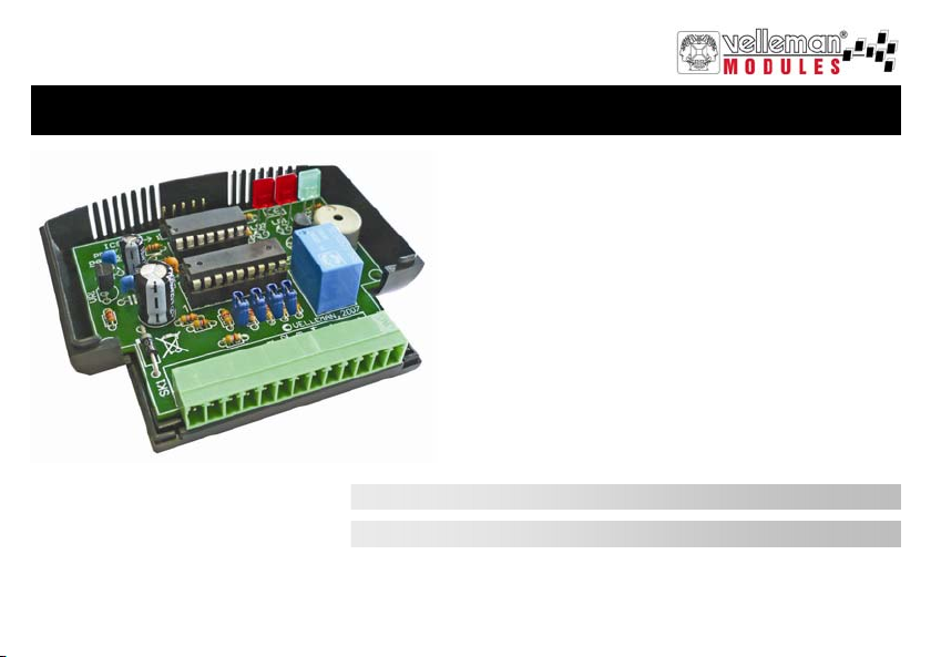
MINI PIC-PLC APPLICATION MODULE
VM142
Mini PIC- P LC a pplicatio n module 2
Mini PIC-PLC toepassingsmodule 12
The translation of this manual and all other information concerning this module can be found on our website : www.velleman.be
Page 2
Safety and warning instructions
WARNINGS
All repairs should be executed by qualified technicians.
Avoid the installation of the module in locations with standing or runni ng water or excessive humidi ty. Indoor use onl y !
Handle the module gentl y and carefully. Dropping it can damage the circuit board and case.
Never exceed the protection limit values indicated in the specifications.
As safety requirement vary, please check with your local authorities.
No objects or liquids should be allowed to penetrate the housing.
Disconnect the module from the AC power before connecting new devices.
Wipe the device with a dry and clean cloth. Do not use detergents or other liquids that may damage the housing.
Keep the device away from children.
Facilitate the operation of the device by familiarising yourself with its adjustments and indications.
Velleman modules are not suitable for use or as part of life support systems , or systems that might create hazardous situations of kind.
Repair under warranty is only possible with date and proof of purchase.
WARRANTY
This pro duct is gua ranteed agai nst defe cts in compone nts and c onstruct ion fro m the mome nt it i s purcha sed and for a pe riod o f TWO YEAR starting from the date of sale. This
guarantee is only valid if the unit is submitted together with the original purchase invoice. VELLEMAN components Ltd limits its responsibility to the reparation of defects or,
as VELLEMAN components Ltd deems necessary, to the replacement or reparation of defective components. Costs and risks connected to the transport, removal or placement o f the pro duct, or any ot her cost s direc tly or indi rectly conne cted to the repa ir, will not be re imburs ed by VEL LEMAN co mponents Ltd. VELLEMAN components Ltd will
not be held res ponsible for any da mages caused by the malfuncti oning of a uni t.
SAFETY INSTRUCTIONS
2
Page 3
SPECIFICATIONS & FEATURES
2
3 1
4
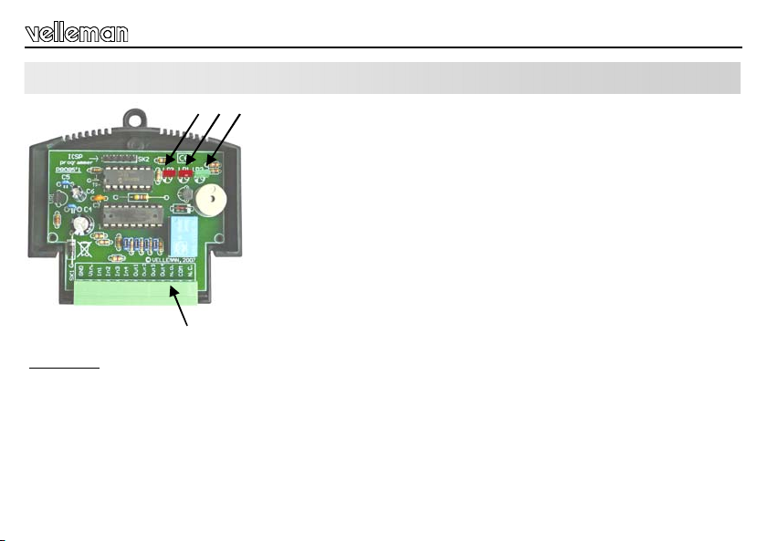
Description
-1- Diagnose LED
-2- Relaycontrol LED
-3- Power supply indication
-4- Terminal block
See also connection diagram on page 7...9
Specifications & features
The VM142 is equipped with a popular 8-bit Microchip® microcontroller. The
PCB layout is designed in such way to include 4 buffered inputs and outputs, a
potential-free relay output and an onboard buzzer. The PIC™ microcontroller is
freely programmable and the software can be developed in Assembler,C or
even special versions of Basic,Pascal,... Note that a certain level of experi-
ence in PIC™ microcontrollers and their programming is required.
Visit www.velleman.be and download software examples.
FEATURES
9 freel y programmable inputs and outputs (4 inputs, 5 outputs)
onboard Microchip
LED indication for power supply and relay output
1 freely programmable LED indication
onboard buzzer
output transistor can be easily repl aced
ICSP™ connector for direct controller programming
You need a PIC™ programmer supporting the PIC16F630, e.g. VM134 (K8076), for
programming this module.
SPECIFICATIONS
• Power supply: 12VDC / 100m A
®
PIC16F630 microc ontroll er
• 4 NPN transistor inputs / 4 NPN transistor outputs
• 1 relay output with NO/NC contact (24VDC / 2A)
• MCU speed: fixed 4MHz internal oscillator
• Input signal voltage: 5 – 24VDC, max. 10mA
• max. transistor output current: 100mA each
• dimensi on: 80 x 70 x 25mm
3
Page 4
Descriptions of the terminal block
DESCRIPTIONS OF THE TERMINAL BLOCK
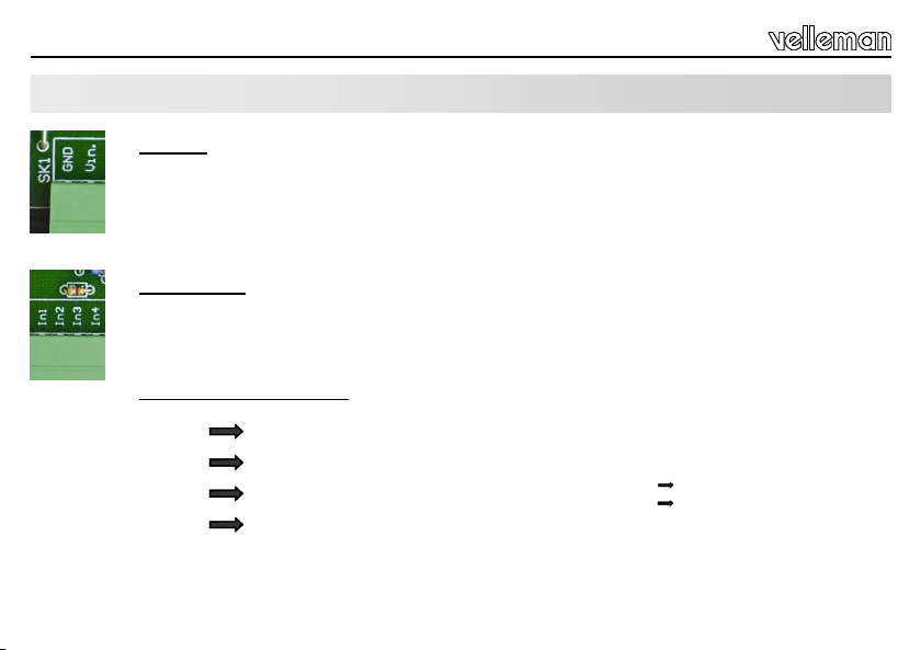
GND-Vin:
Connect the power supply between connections GND and Vin. Apply a direct voltage of 12V (regulated or not
regulated) between the two pins. The electronics of the module are protected against polarity inversion.
The 12V DC must be connected to the “Vin” terminal, your ground level to the “GND” terminal.
In1,In2,In3,In4:
These are the four module inputs which can be activated by applying a direct voltage between 5 and 24V.
The input impedance is 4.7K.
Note that a voltage exceeding 24V can damage the input transistor.
I/O of the PIC16F630: PORT A
INPUT1 I/O 3
INPUT2 I/O 2
INPUT3 I/O 1
INPUT4 I/O 0
Programming example :
BTFSC PORTA,INPUT1 ;Read status of input 1
GOTO INPUT1_NOT_ACTIVE ;’1’ Not active
GOTO INPUT1_ACTIVE' ;’0’ active (5V ... 24VDC)
4
Page 5
Descriptions of the terminal block
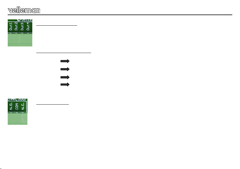
Out1,Ou t2,Ou t3,Out4:
These are the four open-collector type outputs and can each handle a current of max. 100mA.
These transistors are grouped in a transistor array chip, IC2. In case of damage of one of the four inputs or
outputs, this IC type ULN2803A can be replaced easily and without soldering.
I/O of the PIC16F630: PORT C
OUTPUT1 I/O 5
OUTPUT2 I/O 4
OUTPUT3 I/O 3
OUTPUT4 I/O 2
N.O. - COM - N.C.
Output 5 is voltage-free relay contact with double operation. COM is the common contact, NO is the normally
open contact, NC is the normally closed contact
Programming example :
BSF PORTC,RELAY ;activate the relay.
BCF PORTC,RELAY ;deacti vate the relay
Programming example:
BSF PORTC,OUTPUT1 ;activate output 1
BCF PORTC,OUTPUT2 ;deactivate output 2
5
Page 6
Descriptions of the terminal block
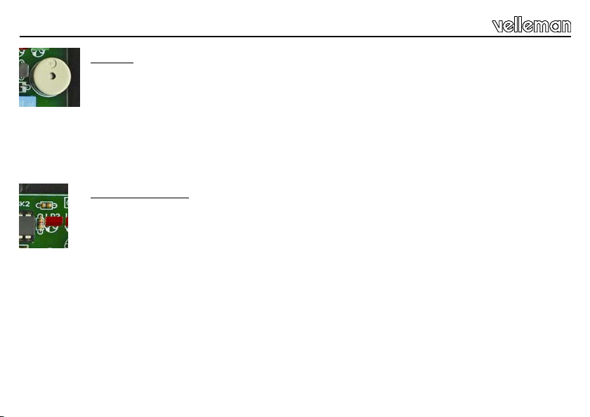
BUZZER:
The built-in buzzer with fixed frequenc y can be activated and deactivated in your program.
Programming example:
BSF PORTC,BUZZER ;activate the buzzer
BCF PORTC,BUZZER ;deactivate the buzzer
Diagnose LED (LD3):
This LED is fixed connected to an I/O of the PIC controller and can be freely programmed.
The built-in LED can be activated as follows:
Programming example:
BSF PORTA,DIAGLED ;activate the led.
BCF PORTA,DIAGLED ;activate the led.
6
Page 7

Connection examples
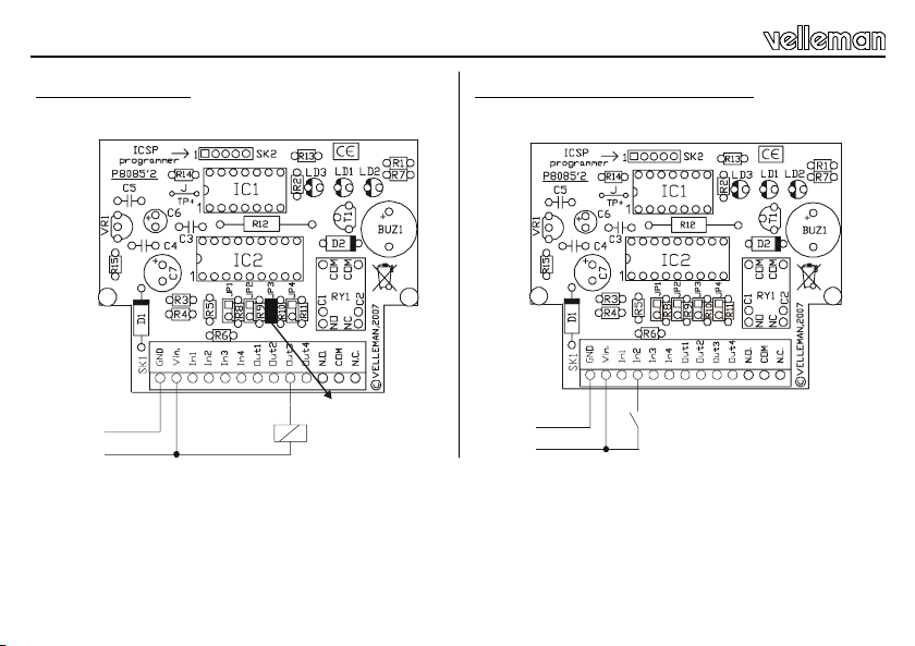
CONNECTION EXAMPLES
Connection of a load (e.g. Motor) In circuit connection between VM142 and VM134/K8076
7
Page 8
Connection examples
Connection of a relay
GND
+12V
Jumper “Jp3” closed
12V relay
Connection of a switch, push button…
GND
+12V
8
Page 9

Connection examples
Connection of a LED
* Remove jumper "JP4"
Connection of two or more LEDs to the same output
9
Page 10

Use
USE
The controller (type PIC16F630) can be programmed in Microchip
The compiler HEX file can be programmed using one of our PIC™ programmers K8048, K8076, VM111, VM134.
The programming method whit the controller remaining onto the PCB is called in-circuit (via the ICSP connector).
The controller chip can also be removed out of the IC socket and be inserted into an external programmer.
Using the in-circuit method implies that no input may be acti vated during the programming process. The output status is also
undetermined. Make sure to avoid damages due to an uncontrolled energizing of the relays.
Please visit www.velleman.be
JUMPERS JP1 to JP4:
and download an exemplary program with Assembler source code.
These jumpers allow you to limit the maximum output current so as to connect a LED directly to the output.
A 1K resistance will be placed in series with the output when you remove the jumper. This value is the value needed to
activate a standard LED at a power voltage of 12V.
I led = (U – Uled) / R v (12 – 1.6) / 1000 = 0.0104 10mA.
JP1 Output1, …..
®
PIC™ Assembler and other compilers.
10
Page 11

TEST
The VM142 is pre-programmed with a test program allowing you to test all inputs and outputs of the module.
The program can be read as follows:
The diagnose LED blinks when applying voltage to the module.
Activate input 1
Activate input 2
Activate input 3
Activate input 4
After the activation of the 4 inputs, the relay will energize a couple of times and the buzzer will sound.
This program will be erased when you overwrite it with your own program.
You will find the source code and a header file on our website.
Output 1 is energized.
Output 2 is energized.
Output 3 is energized.
Output 4 is energized.
Test
11
Page 12

Veiligheidsaanwijzingen en waarschuwingen
WAARSCHUWING
Reparaties mogen uitsluitend uitgevoerd worden door vakkundige personen.
Installeer de module niet op plaatsen met staand of stromend water of in ruimtes met een te hoge vochtigheidsgraad.
Binnengebruik enkel!
Vermijd een ruwe behandeling. Stoten of laten vallen kunnen ernstige schade aanbrengen.
Overschrijdt nooit de opgegeven veiligheidswaarden in de specificaties.
Vermits de veiligheid vereisten verschillen van plaats tot plaats, zorg daarom dat Uw montage voldoet aan de plaatselijke
geldende vereisten.
Let op dat er geen voorwerpen of vloeistoffen in het toestel dringen.
Zorg ervoor dat de netspanning altijd uitgeschakeld is bij het aansluiten van nieuwe toestellen.
Houdt vooral kinderen uit de buurt van het toestel dit ter veiligheid van hun zelf.
Zorgt ervoor dat u met alle bedieningselementen vertrouwd raakt, wanneer U met het toestel zal werken.
Velleman modules zijn niet geschikt voor gebruik in of als gedeelte van systemen welke levensfuncties in stand houden of
systemen welke gevaarlijke situaties van gelijk welke aard kunnen veroorzaken.
Herstelling onder garantie is enkel mogelijk met aankoopbewijs.
WAARBORG
Dit pr odukt is gewaar borgd wat betre ft gebre ken in mate riale n en vakmans chap o p het oge nblik va n de aanko op en di t gedure nde een pe riode van TWE E JAAR vana f de
aankoop. De waarborg geldt enkel indien het produkt voorgelegd wordt samen met het orig ineel aankoop bewijs. De verpli chti ngen van VE LLEMAN COMPONE NTS N.V .
beperk en zich t ot het hers tellen van def ecte n of, na ar vri je keu ze van VEL LEMAN COMPONE NTS N.V. , tot het ve rvangen o f hers tellen van defecte onderdelen. Kosten en
ris ico’s van t ranspo rt; het w egnemen en t erugpla atse n van het pro dukt, e venals o m het eve n welke ande re kost en die rec htst reeks of onr echts treeks verband houden met de
herstelling, worden niet door VELLEMAN COMPONENTS N.V. vergoed. VELLEMAN COMPONENTS N.V. is niet verantwoordelijk voor schade van gelijk welke aard,
ver oorzaakt door he t falen v an een product .
VEILIGHEID SAANWIJZINGEN
12
Page 13

TECHNISCHE GEGEVENS & EIGENSCHAPPEN
2
3 1
De VM142 heeft een zeer populaire 8-bit microcontroller van Microchip aan boord
en de hardware layout is zo ontworpen dat er 4 gebufferde in- en uitgangen zijn.
Verder is er ook een potentiaalvrije relaisuitgang en een zoemer geïntegreerd. Dit
alles maakt deze module veelzijdig. De PIC microcontroller is door U vrij te
programmeren. De software kan ontwikkeld worden in Assembler, C of zelfs
speciale versies van Basic, Pascal... Een zekere graad van ervaring met PIC
microcontrollers en hun programmatie is vereist.
Software voorbeelden kan je downloaden via onze website: www.velleman.be
EIGENSCHAPPEN
9 vrij programmeerbare in- en uitgangen. ( 4 in-, 5 uitgangen)
Geïntegr eerde PIC16F630 Microcontroller van Microchip®
LED indicatie voor de voedingsspanning en relais uitgang.
1 vrij programmeer bare LED indicatie.
Ingebouwde zoemer.
Zeer eenvoudige vervanging van de uitgangstransistors.
Beschrijving
-1- Diagnose LED
-2- Controle relais LED
-3- Voedingsindicatie
-4- Aansluitingsconnector
4
Zie aansluitschema's pag. 17 … 19
ICSP™ connector voor rechtstreekse programmatie van de controller.
Om deze module te programmeren is er een PIC™ progr ammer vereist die de
PIC16F630, bv. de VM134 (K8076), ondersteunt.
TECHNISCHE GEGEVENS
• Voeding: 12V DC / 100mA.
• 4 NPN transistor ingangen - 4 NPN transistor uitgangen.
• 1 relais uitgang met NO/NC contact (24VDC / 2A).
• Klokfrequentie controller: 4MHz vaste interne oscillator.
• Ingangss panning: 5 – 24VDC, max 10mA.
• Max schakelstroom: 100mA per kanaal.
• Afmetingen: 80x70x25mm.
Technische gegevens & eigenschappen
13
Page 14

Beschrijving aansluitklemmen
BESCHRIJVING VAN DE AANSLUITKLEMMEN
GND-Vin:
De voedingsspanning wordt aangesloten tussen de aansluitingen GND en Vin. Leg tussen deze pennen een
gelijkspanning aan van 12 (gestabiliseerd of ongestabiliseerd). De elektronica van de module zelf is
beschermd tegen polariteitinversie. Sluit de 12V DC aan de ‘Vin’-terminal; sluit de aarding aan de ‘GND’terminal.
In1,In2,In3,In4:
Dit zijn de 4 ingangen van de module. Deze ingangen kunnen worden actief gemaakt door er een
gelijkspanning tussen 5 en 24V op aan te bieden. De ingangsimpedantie van deze klemmen is 4,7 K.
Een spanning hoger dan 24V kan de ingangstransistor beschadigen.
I/O poort van de PIC16F630: POORT A
INPUT1 I/O 3
INPUT2 I/O 2
INPUT3 I/O 1
INPUT4 I/O 0
Programma voorbeeld:
BTFSC PORTA,INPUT1 ;Lees status van ingang 1
GOTO INPUT1_NOT_ACTIVE ;’1’ geen spanning
GOTO INPUT1_ACTIVE' ;’0’ Actief (5V ... 24VDC)
14
Page 15

Beschrijving aansluitklemmen
Out1,Ou t2,Ou t3,Out4:
Dit zijn 4 uitgangen van het ‘open-collector’ type. Zij kunnen max 100mA per uitgang schakelen. Deze
transistoren zitten samen gebundeld in een transistor array chip, IC2. Bij een defect van één van de 4 in- of
uitgangen kan dit IC, type ULN2803A snel worden vervangen, dit zonder soldeerwerk.
I/O poort van de PIC16F630: POORT C
OUTPUT1 I/O 5
OUTPUT2 I/O 4
OUTPUT3 I/O 3
OUTPUT4 I/O 2
N.O. - COM - N.C.
Dit is uitgang 5, dit is een spanningloos relaiscontact met dubbele werking. COM is de gemeenschappelijke,
NO is het normaal open contact, NC is het normaal gesloten contact.
Programma voorbeeld:
BSF PORTC,RELAY ;Activeer het relais
BCF PORTC,RELAY ;Deactiveer het relais
Programma voorbeeld:
BSF PORTC,OUTPUT1 ;Activeer uitgang 1
BCF PORTC,OUTPUT2 ;Deactiveer uitgang 2
15
Page 16

Beschrijving aansluitklemmen
BUZZER:
De ingebouwde zoemer met vaste frequentie kan in het programma geactiveerd en gedeactiveerd worden.
Programma voorbeeld:
BSF PORTC,BUZZER ;Activeer de zoemer
BCF PORTC,BUZZER ;Deactiveer de zoemer
Diagnose LED (LD3):
De vaste led is aangesloten op een in-/uitgang van de PIC™ controller en is vrij programmeerbaar.
De ingebouwde led wordt als volgt geacti veerd:
Programma voorbeeld:
BSF PORTA,DIAGLED ;Activeer de led
BCF PORTA,DIAGLED ;Deactiveer de led
16
Page 17

Aansluitvoorbeelden
AANSLUITVOORBEELDEN
Aansluiten van een belasting (vb. motor) "In circuit" verbinding tussen VM142 en VM134/K8076
17
Page 18

Aansluitvoorbeelden
Aansluiten van een relais
GND
+12V
Jumper “Jp3” closed
12V relay
Aansluiten van een schakelaar, drukknop, ...
GND
+12V
18
Page 19

Aansluitvoorbeelden
Aansluiten van een led
* verwijder shunt "JP4"
Aansluiten van 2 of meerdere LEDs op dezelfde uitgang
19
Page 20

Gebruik
GEBRUIK
De controller van het type PIC16F630 kan worden geprogrammeerd in PIC assembler van Microchip, maar ook door andere
3rd party compilers.
Het afgeleverde HEX bestand door een compiler pakket kan met één van onze PIC programmers:
K8048,K8076,VM111,VM134 geprogrammeerd worden.
Als de controller op de print blijft zitten van de VM142 wordt de methode van programmering “in circuit” genoemd. (via de
ICSP connector), de controller chip kan ook uit het IC voet worden genomen en in een externe programmer worden gestopt.
Als de “in circuit” methode gebruikt mag tijdens het programmeringproces geen enkel ingang worden geactiveerd. Ook de
toestand van de uitgangen is onbepaald en men dient voorzorgen te nemen dat er geen schade kan ontstaan doordat bvb
relais ongecontroleerd aantrekken.
Een voorbeeld programma, met assembler source code kan je downloaden via onze website, www.velleman.be
JUMPER JP1 tot JP4:
Met deze jumpers kan je de maximale uitgangsstroom beperken zodat bvb een LED rechtstreeks op de uitgangs kan worden
aangesloten.
Verwijderd men deze jumper dan wordt in serie met de uitgang een weerstand van 1K geplaatst. Dit is de waarde nodig om
een standaard LED op te laten lichten bij een module voedingsspanning van 12V
I led = (U – Uled) / R v (12 – 1.6) / 1000 = 0.0104 10mA.
JP1 Output1, …..
20
Page 21

Test
TEST
De VM142 is in de fabriek voorgeprogrammeerd met een testprogramma. Hiermee is het mogelijk al de in- en uitgangen van
de module te testen.
Het programma zit schematisch zo in elkaar:
De diagnose LED knippert bij het onder spanning zetten van de module.
Activeer ingang 1
Activeer ingang 2
Activeer ingang 3
Activeer ingang 4
Nadat de 4 ingangen zijn geactiveerd zal het relais een paar keer aantrekken en de zoemer een paar keer weerklinken.
Dit programma wordt gewist als het door de gebruiker wordt overschreven met zijn eigen programma.
Je vind de source code en een header bestand om zelf mee aan de slag te gaan terug op onze website.
Uitgang 1 wordt bekrachtigd.
Uitgang 2 wordt bekrachtigd.
Uitgang 3 wordt bekrachtigd.
Uitgang 4 wordt bekrachtigd.
21
Page 22

To all resi dents of the E uropean U nion
Aan al le ingezetenen van de Europese Unie
Aux résidents de l'Uni on Europ éenne
An all e Einwohner der Eur opäischen Union
A los ciudad anos de la Unión Europ ea
A todos os cidadã os da Uni ão Euro peia
A tutti i cittadini dell’Unione eur opea
UK
NL
FR D ES
IT
PT
Belangrijke milieu-informatie betreffende dit product Dit symbool op het toestel of de verpakking geeft aan dat, als het na zijn levenscyclus wordt weggeworpen, dit
toes tel scha de kan toebre ngen aan het mi lieu. Gooi dit toestel ( en event uele bat terijen) ni et bij het gewo ne
huishoudelijke afval; het moet bij een gespecialiseerd bedrijf terechtkomen voor recyclage. U dient dit toestel naar
uw verdeler of naar een lokaal recyclagepunt te brengen. Respecteer de plaatselijke milieuwetgeving.
Heeft u vragen, contacteer dan de plaatselijke autoriteiten inzake afvalverwijdering.
Des informations environnementales importantes concernant ce produit
Important environmental information about this product This symbol on this unit or the package, indicates that disposal of this unit after its lifecycle could harm the environment.
Do not dispose the unit as unsorted municipal waste; it should be disposed by a specialized company for recycling. This
unit should be returned to your distributor or to a local recycling service. Respect the local environmental rules.
If any doubt contact your local authorities about waste disposal rules.
ENG
DUT
Ce symbole s ur l'apparei l ou l'emballage indique que, si l'appareil est jeté après sa vie , il peut nuire à l'environnement. Ne
FR
Dies es Symbol a uf dem Pro dukt oder der Verpa ckung zei gt an, da ss die E ntsorgung dieses Produkte s nach sei nem
Lebe nszyklus der Umwelt S chaden zufügen ka nn. Ents orgen Sie die Einhe it (ode r verwe ndeten Bat terie n) nicht als unsortie rtes
Hausm üll; die E inheit o der ver wendeten B atteri en müssen v on einer s pezialis ierten F irma zwec ks Recyc ling entso rgt werd en.
Diese Einheit muss an den Händler oder ein örtliches Recycling-Unternehmen retourniert werden. Respektieren Sie die
örtli chen Umwe ltvors chrifte n.
Wichtige Umweltinformationen über dieses Produkt
jetez pas cet appareil (et des piles éventuelles) parmi les déchets ménagers ; il doit arriver chez une firme spécialisée
pour recyclage. Vous êtes tenu à porter cet appareil à votre revendeur ou un point de recyclage local. Respectez la
législation e nvironnementa le locale.
Si vous avez des questions, contactez les autorités locales pour élimination de déchets
D
Falls Zweifel bestehen, wenden Sie sich für Entsorgungsrichtlinien an Ihre örtliche Behörde.
Importantes informaciones sobre e l medio ambiente concerniente este producto Este símbolo en este aparato o el embalaje indica que, si tira las muestras inservibles, podrían dañar el medio ambiente. No tire
ES
Informação ambie ntal importante sobre este produto Este s ímbolo, inc luído na u nidade o u pacote, s ignifica que após o se u ciclo de vi da deve pr estar ate nção onde o
este aparato (ni las pilas eventuales) en la basura doméstica; debe ir a una empresa especializada en reciclaje. Devuelva este
aparato a su distribuidor o un lugar de reciclaje local. Respecte las leyes locales en relación con el me dio ambiente.
Si tiene dudas, contacte las autoridades locales para la eliminación de residuos
PT
Importanti info rmazioni ambienta li riguardo a questo prodotto Questo simbolo sul prodotto o l’imballaggio indica che è vietato smaltire il prodotto nell’ambiente al termine del suo ciclo
vitale in quan to può essere nocivo per l’ambiente stesso. Non s maltire il prodotto (o le pile se util izzate) come rifi uto
urbano indifferenziato ; dovrebbe essere smaltito da un’impresa specializzata nel riciclaggio. Questo prodotto dovre bbe
essere restituito al distributo re o ad un’impresa di riciclaggio loca le. Ris pettare le norme ambientali locali.
vai co locar pois po de danifica r o meio ambient e. Não co loque a uni dade (o u bater ias se uti lizadas) junt amente co m
outro s produtos ; deve colocar nos rec ipient es própr ios par a recic lagem. Esta uni dade deve se r entregue a o seu
distribuidor ou colocada em recipiente próprio para reciclagem. Respeite o ambiente!
Em caso de dúvida contacte as autoridades da sua área.
In caso di dubb io, contattare l’ammin istrazione comunale per informaz ioni in mater ia di sma ltimento dei rifiuti.
IT
Page 23

ανακύκλωσης. Η µον άδα αυτή πρέπει να επιστραφεί στον
Til alle innbyggere i Den Europeiske Union
Til alle beboere i den Eur opæisk e Unio n (EU)
Kaikille Eur oopan Unionin kansalaisille
Do wszystk ich obywateli Uni i Europejskiej
Všem obyvatelům Evropské Unie.
Tüm Avr upa Birl iği vatandaşlarına
Προς όλους τους πολίτες της Ευρωπαϊκής Έν ωσης
TJ
PL
TR
NO
DK
FIN
EL
środowi sku. Urządzeń (lub ba terii, jeżeli były używane) nie należy wyrzucać tak jak ni esort owanyc h odpadków ko munalny ch.
Viktig miljöinformation om denna produkt
SE
Powi nna je usunąć wyspecjalizowana firma w celu recyklingu. Urządzenie to należy zwrócić dys trybutoro wi lub mie jscowym
Denna s ymbol på enhe ten elle r på fö rpackni ngen anger at t anvä ndning av denna e nhet efte r dess li vstid kan va ra
skadli g för miljön. Deponer a EJ enhet en (elle r batterierna , om sådana anv änds) s om osort erat kommunalt avfall;
det s kall depone ras av ett profess ionellt bola g för återvi nning. Enhete n skall åte rsända s till din di stributö r eller t ill ett
lokalt återvinningsbolag.Respektera de lokala bestämmelserna för återvinning.
Vid minsta tvekan kon takta den lokala mynd igheten om v ilka bestämmelser, som gä ller för av fallsdeponering.
Viktig miljøinformasjon om dette produktet Dette symbolet på denne enheten eller pakken betyr at enheten kan skade miljøet dersom den kastes etter endt
leve tid. I kke kast enheten (eller batterie r dersom diss e er brukt) s om usort ert ko mmunalt av fall, den bør kastes av et
særskilt firma for gjenvinning. Denne enheten bør returneres til leverandøren eller til en lokal gjenvinningstjeneste.
Respekter det lokale miljøregle mentet.
Kontakt de lokale myndighetene dersom du skulle være i tvil om reglementet for håndtering av avfall
Tärkeää ympäristöä koskevaa asiaa tästä tuotteesta Oheine n symboli tuo tteessa ta i sen pakkauks essa tarko ittaa sitä, että se n hävittämine n käytön jälke en saattaa
DK
FIN
Ważne informacje o tym produkcie dotyczące środowiska
Ten sy mbol na ur ządze niu lub opakowaniu oznacza, że wyr zucenie tego ur ządzenia po zużyciu mo głoby zaszkodzić
służbom zajmu jącym się recykli ngiem. Należy przestrzegać lokalnych pr ze pisów dotyczących ochrony środowiska.
W razie wątpliwoś ci w sprawie zasad usuwania odpadów należy zwrócić się do władz lokalnych.
Důležité informace o zpracování odpadů k tomuto výrobku. Tento s ymbol na výr obku nebo jeho o balu znamená , že odpad z v ýrobku po skončení doby jeho života může být
škodlivý pro životní prostředí. Nevyhazujte výrobek (nebo případně použité baterie) do komunálního odpadu. Měl by
být předán k recyklaci odborné firmě. Vraťte výrobek vašemu prodejci nebo jej odevzdejte v místním sběrném místě
odpad ů. Dodržujte mís tní předpisy pro nakládání s odpady.
vahingoittaa ympäristöä. Älä hävitä tuotetta (tai sen paristoja) lajittelemattoman tai talousjätteen mukana, se on
toi mitett ava kier rätysla itokseen. Tuo te voidaa n palaut taa jä lleenmyyjälle tai se on toi mitet tava käsittelyla itokseen. Kunnioita paikallisia ympärist ösäänn öksiä .
PL
V přípa dě pochybnos tí se obraťte s dotazem na prav idla nakládání s odpad y na vaše místně příslušné úřady.
Bu ünite deki ya da pakett eki bu sembol, bu üni tenin ö mrünü doldur duktan so nra atılmas ının çevreye zarar
verebileceğini belirtmektedir. Üniteyi (ya da kullanılırsa bataryaları) sınıflandırılma mış be lediye çö pü olara k ortadan
Bu ürün hakkında önemli ç evre bilgileri
kaldırmayınız; özel bir firma tarafından yeni den dönüşüme tabi tutulmak üzere toplanmalıdır. Bu ünite genel
dağıtıcınıza ya da yerel bir yeniden dö nüşüm istasyonuna geri getirilmelidir. Yerel çevre kurallarına saygı gösterini z.
Herhangi bir şüphe durumunda, çöp atım kur alları hakkında yerel yet kililer le irtib ata g eçiniz.
TJ
TR
αστικά απόβλητα. Πρέ πει να απορριφθεί από εξειδικευµένη εταιρία
Αυτό το σύµβολο πάνω στη µονάδα ή στη συσκευασία υποδε ικνύει ότι η απόρριψη της µονάδας µετά το τέλος του κύκλου ζωής
της ενδέχεται να βλάψει το περιβάλλον. Μην απορρίπτετε τη µονάδα (ή τις µπαταρίες αν είναι χρησιµοποιηµέν ες) ως µικτά
διανοµέα σας ή σε τοπική υπηρεσ ία ανακύκλωσης. Να σέβεστε τους τοπικούς περιβαλλοντικούς κανόνες.
Σηµαντι κές πε ριβαλλον τικέ ς πληροφορίες για το προϊόν
Σε περίπτωση αµφιβολίας σχετικά µε τους κανόνες απόρριψης αποβλήτων, επικοινωνήστε µε τις τοπικές αρχές.
EL
Page 24

MINI PIC
MINI PIC
VM142
USER MANUAL
Belgium [Head office] Velleman Components +32(0)9 384 36 11
France Velleman Electronique +33(0)3 20 15 86 15
Netherlands Velleman Components +31(0)76 514 7563
USA Velleman Inc. +1(817)284-7785
Spain Velleman Components +34 954 126800
MINI PIC
-
PLC APPLICATION MODULE
-
PLC APPLICATION MODULE
-
PLC APPLICATION MODULE
5 410329 378561
Modifications and typographical errors reserved - © Velleman Components nv - HVM142- 2007 - ED1
 Loading...