

Page 1
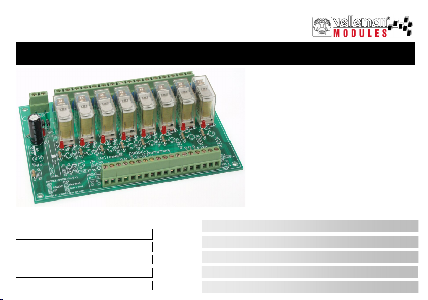
EIGHT CHANNEL RELAY CARD
VM129
Belgium [Head office] +32(0)9 384 36 11
France +33(0)3 20 15 86 15
Netherlands +31(0)76 514 7563
USA +1(817)284-7785
Spain +32(0)9 384 36 11
8-channel relay card 4
8-Kanaals relaiskaart 7
Carte relais à 8 canaux 10
8-Kanal-Relaiskarte 13
Tarjeta relé de 8 canales 16
Page 2

Page 3
Warnings and contents
Thank you for purchasing this module. Please read the instructions carefully to ensure correct and safe use of this device.
WARRANTY
This product is guaranteed against defects in components and construction from the moment it is purchased and for a period of TWO YEAR starting from the
date of sale. This guarantee is only valid if the unit is submitted together with the original purch ase in voic e. VELLEMAN components Ltd limits its responsibility to the reparation of defects or, as VELLEMAN components Ltd deems necessary, to the replacement or reparation of defective components. Costs and
risks connected to the transport, removal or placement of the product, or any other costs directly or indirectly connected to the r epair, will not be reimburse d by
VELLEMAN components Ltd. VELLEMAN components Ltd will not be held responsible for any damages caused by the malfunctioning of a unit.
CONTENTS :
FEATURES & SPECIFICATIONS .................................................................................................................................................................... 4
POWER SUPPLY................................................................................................................................................................................................ 5
INPUT CONNECTION EXAMPLES ................................................................................................................................................................. 6
OUTPUT CONNECTION EXAMPLE ............................................................................................................................................................... 8
SAFETY AND W ARNING INSTRUCTIONS ................................................................................................................................................... 9
READ THE OPERATING AND MAINTENANCE INSTRUCTIONS IN
THIS USER’S GUIDE CAREFULLY.
3
Page 4

Specifications & features
SPECIFICATIONS & FEATURES
FEATURES
Eight high quality relay contacts, 5A/230VAC max.
Relay outputs are transient suppressed using VDR’s.
LED confirmation on each relay contact.
Eight drive inputs to use with open collectors or regular switches.
Ideal for use with our computer interface card VM110 or infrared remote control receiver VM122.
SPECIFICATIONS
• Power: 12Vac / 500mA (including 12V output)
• Unregulated 12Vdc / 200mA power output (for VM122)
4
Page 5
POWER SUPPLY
AC
INPUT
12V
NO
1
NO
2
NO
3
MAINS
1 x 12V / 500m A
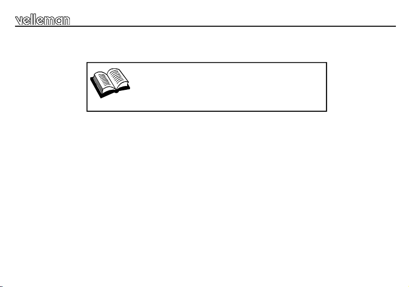
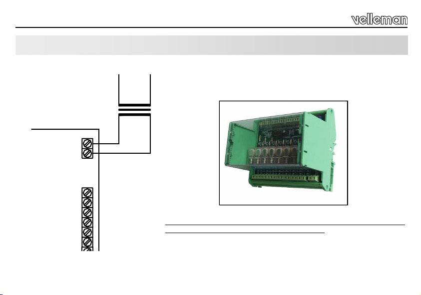
Power supply
Choose a suitable location for the unit. Probably, the best location is near
Ordernr. Transformer : 112006C
the fuse box. An optional enclosure (B8006) is available, for safe installation
of the unit on a DIN rail.
Ordernr. T ransformer : 112006C
The drawings on the next pages shows connection examples with different
input possibilities.
B8006 Optional Din rail enclosure
Make sure your wiring complies with the local safety requirements.
If doubt, consult a licensed technician !
5
Page 6
Input connection examples
INPUT CONNECTION EXAMPLES
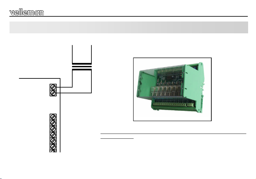
15-channel infrared receiver 'VM122' :
The connection diagram (Fig. 1.0) shows how
to connect relays to the interface card VM122.
The 15 outputs of VM122 are open-collector
outputs, which means they are transistors used
as switches. When an output is active, a closed
contact is created between ground (GND) and
that output.
As shown in the connection diagram, one
single power supply can be used for the receiver module as well as e.g. for the relay
switch.
Note : You can use the VM121 infrared
transmitter to control your applications.
6
VA
GND
VB
+V
VCOM
Ordernr. Transformer : 112006C
MAINS
VM129 VM122
Figure 1.0
0
IN
0
1
2
3
4
5
6
7
8
9
10
11
12
13
14
15
+
+12V
0
1
0
2
0
3
0
4
0
5
0
6
0
7
0
8
INPUT
RS232
Vout
12V
INPUT
AC
NO
NO
NO
NO
NO
NO
NO
NO
1 x 12V / 500mA
1
2
3
4
5
6
7
8
Page 7
Input connection examples
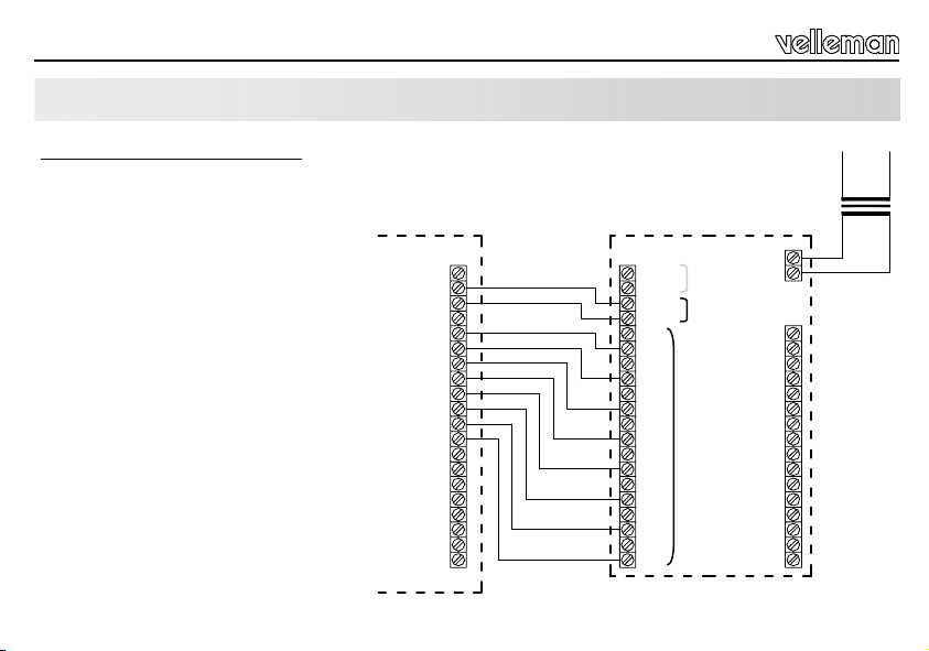
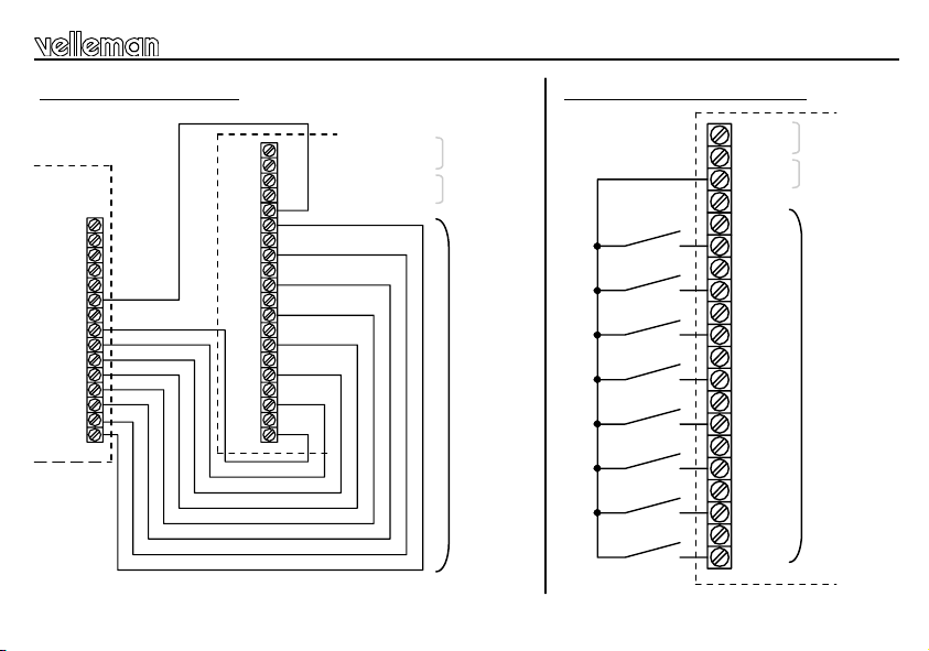
USB Interface Card 'VM110' :
VM110
GND
PWM2
DAC2
PWM1
DAC1
GND
CLAMP
08
07
06
05
04
03
02
01
Connection with regular switches :
0
IN
0
+12V
0
1
0
2
0
3
0
4
0
5
0
+12V
0
IN
0
0
1
0
2
0
3
0
4
0
5
0
6
0
7
0
8
VM129
RS232
V out
INPUTS
6
0
7
0
8
Figure 2.0
RS232
V out
INPUTS
Figure 3.0
7
Page 8
Output connection example
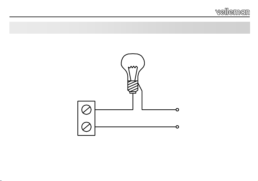
OUTPUT CONNECTION EXAMPLE
NO
1
8
230V
230V
Page 9
Safety & warning instructions
WARNINGS
All repairs should be executed by qualified technicians.
Handle the module gently and carefully. Dropping it can damage the circuit board.
Avoid the installation of the module in locations with standing or running water or excessive humidity. Indoor
use only !
SAFETY INSTRUCTIONS
Never exceed the protection limit values indicated in the specifications.
As safety requirement vary, please check with your local authorities.
Facilitate the operation of the device by familiarising yourself with its adjustments and indications.
Velleman modules are not suitable for use or as part of life suppo rt systems, or systems that might create hazardous situations of kind.
Repair under warranty is only possible with date and proof of purchase.
9
Page 10
Waarschuwingen en inhoud
Hartelijk dank voor de aanschaf van deze module. Lees de gebruiksaanwijzing aandachtig, zodat u het apparaat op de juiste
manier gebruikt.
WAARBORG
Dit produkt is gewaarborgd wat betreft gebreken in materialen en vakmanschap op het ogenblik van de aankoop en dit gedurende een periode van TWEE
JAAR vanaf de aankoop. De waarborg geldt enkel indien het produkt voorgelegd wordt samen met het origineel aankoop bewijs. De ver plichtinge n van
VELLEMAN COMPONENTS N.V. beperken zich tot het herstellen van defecten of, naar vrije keuze van VELLEMAN COMPONENTS N.V., tot het vervangen
of herstellen van defecte onderdelen. Kosten en risico’s van transport; het wegnemen en terugplaatsen van het produkt, evenals om het even welke andere
kosten die rechtstreeks of onrechtstreeks verband houden met de herstelling, worden niet door VELLEMAN COMPONENTS N.V. vergoed. VELLEMAN
COMPONENTS N.V. is niet verantwoordelijk voor schade van gelijk welke aard, veroorzaakt door het falen van een product.
CONTENTS
KENMERKEN & SPECIFICATIES ................................................................................................................................................................. 11
LEES DE GEBRUIKS - EN ONDERHOUDSAANWIJZINGEN VAN DE
HANDLEIDING ZORGVULDIG DOOR.
VOEDING........................................................................................................................................................................................................... 12
AANSLUITINGSVOORBEELDEN VOOR DE INGANGEN ........................................................................................................................ 13
AANLSUITINGSVOORBEELD VOOR DE UITGANG ................................................................................................................................ 15
VEILIIGHEIDSAANWIJZINGEN EN WAARSCHUWINGEN ...................................................................................................................... 16
10
Page 11

Eigenschappen en technische gegevens
EIGENSCHAPPEN & TECHNISCHE GEGEVENS
EIGENSCHAPPEN
8 hoogwaardige relaiscontacten, 5A/230Vac max.
Relaisuitgangen onderdrukken pieken d.m.v. VDRs
Bevestiging via LED op ieder relaiscontact
8 stuuringangen voor gebruik met open collector of gewone schakelaars.
Ideaal in combinatie met onze computer interfacekaart VM110 of infrarood ontvanger VM122.
TECHNISCHE GEGEVENS
• Ingangsspanning: 12Vac / 500mA (met 12V-uitgang)
• Uitgerust met 12Vdc / 200mA vermogensuitgang (voor voeding VM122)
11
Page 12
Voeding
VOEDING
INPUT
12
AC
12V
NO
NO
NO
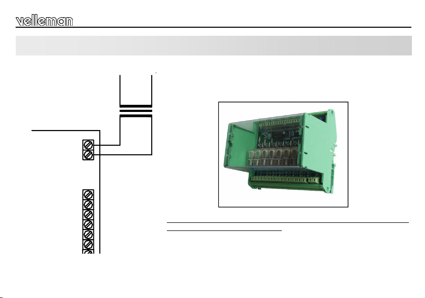
Kies een geschikte locatie voor de installatie van de unit. Waarschijnlijk zult
Ordernr. Transformer : 112006C
MAINS
1 x 12V / 500m A
1
2
3
u de unit installeren in de nabijheid van een zekeringkast. Een geschikte
behuizing voor DIN-rail montage is leverbaar, zodat de unit op een nette en
Ordernr. T ransformer : 112006C
veilige wijze kan ingebouwd worden (ordercode B8006).
De figuren op de volgende pagina’s tonen u één van de verschillende
mogelijkheden voor he t aansluiten van de ingangen
B8006 Optionele DIN-rail behuizing
Zorg ervoor dat de montage en aansluiting voldoet volgens de
geldende veiligheidsvoorschriften. Bij twijfel, raadpleeg een vakman !
Page 13

AANSLUITINGSVOORBEELDEN VOOR DE INGANGEN
15- kanaals infrarood ontvanger 'VM122' :
In het bedradingsschema (Fig. 1.0) ziet u hoe u
relais moet aansluiten op de VM122
interfacekaart.
De 15 uitgangen van VM122 zijn “opencollector” uitgangen: het zijn dus transistors
gebruikt als schakelaar. Bij een actieve uitgang
ontstaat een gesloten contact tussen de massa
(GND) en de desbetreffende uitgang.
Zoals de volgende aansluitschema’s tonen, kan
je één enkele voeding gebruiken voor zowel de
ontvangstmodule als bvb. het relais.
Opmerking : U kunt de VM121 IR zender
gebruiken om uw toepassingen aan te sturen.
VA
GND
VCOM
VB
+V
1
2
3
4
5
6
7
8
9
10
11
12
13
14
15
+
Figure 1.0
Aansluitingsvoorbeelden voor de ingangen
Ordernr. Transformer : 112006C
MAINS
VM129 VM122
AC
0
IN
0
+12V
0
1
0
2
0
3
0
4
0
5
0
6
0
7
0
8
RS232
Vout
INPUT
12V
INPUT
NO
NO
NO
NO
NO
NO
NO
NO
1 x 12V / 500mA
1
2
3
4
5
6
7
8
13
Page 14

Aansluitingsvoorbeelden voor de ingangen
USB interface kaart 'VM110' :
VM110
GND
PWM2
DAC2
PWM1
DAC1
GND
CLAMP
08
07
06
05
04
03
02
01
14
D.m.v drukknopen, schakelaars, ... :
0
IN
0
+12V
0
1
0
2
0
3
0
4
0
5
0
+12V
0
IN
0
0
1
0
2
0
3
0
4
0
5
0
6
0
7
0
8
VM129
RS232
V out
INPUTS
6
0
7
0
8
Figure 2.0
RS232
V out
INPUTS
Figure 3.0
Page 15

AANSLUITINGSVOORBEELD VOOR DE UITGANG
NO
1
Aansluitingsvoorbeeld voor de uitgang
230V
230V
15
Page 16

Veiligheidsaanwijzingen en waarschuwingen
WAARSCHUWING
Reparaties mogen uitsluitend uitgevoerd worden door vakkundige personen.
Installeer de module niet op plaatsen met staand of stromend water of in ruimtes met een te hoge vochtigheidsgraad. Binnengebruik enkel!
Vermijd een ruwe behandeling. Stoten of laten vallen kunnen ernstige schade aanbrengen.
VEILIGHEID SAANWIJZINGEN
Overschrijdt nooit de opgegeven veiligheidswaarden in de specificaties.
Vermits de veiligheid vereisten verschillen van plaats tot plaats, dient U ervoor te zorgen dat Uw montage voldoet aan de plaatselijke geldende vereisten.
Zorgt ervoor dat u met alle bedieningselementen vertrouwd raakt, wanneer U met het toestel zal we rken.
Velleman modules zijn niet geschikt voor gebruik in of als gedeelte van systemen welke levensfuncties in stand houden of systemen welke gevaarlijke
situaties van gelijk welke aard kunnen veroorzaken.
Herstelling onder garantie is enkel mogelijk met aankoopbewijs.
16
Page 17

Avertissements et sommaire
Nous vous félicitons pour l’achat de ce module. Lisez attentivement le mode d’emploi de façon à utiliser l’appareil de manière
adéquate.
GARANT IE
Ce pr oduit est garanti contr e les déf auts des c omposantes e t de fabr ication a u moment de l’achat, et ce pour une pério de de DEU X ANS à partir de la date
d’achat. Cette garantie est uniquement valable si le produit est accompagné de la preuve d’achat originale. Les obligations de VELLEMAN COMPONENTS
S.A. . se limitent à la réparation des défauts ou, sur seule décision de VELLEMAN COMPONENTS S.A. au remplacement ou à la réparation des pièces
défectueuses. Les frais et les risques de transport, l’enlèvement et le renvoi du produit, ainsi que tous autres frais liés directement ou indirectement à la
réparation, ne sont pas pris en charge par VELLEMAN COMPONENTS S.A.
VELLEMAN C OMPONEN TS S.A. n’est pas responsable des dégâts, que ls qu’ils soie nt, provoqués par le ma uvais fonctionnement d’ un produit.
CONTENTS :
CARACTERISTIQUES & DONNEES TECHNIQUES .................................................................................................................................18
LIRE ATTENTIVEMENT LES INSTRUCTIONS DE SERVICE ET DE
MAINTENANCE DU PRESENT MANUEL..
ALIMENT ATION ................................................................................................................................................................................................19
EXEMPLES DE CONNEXION D'ENTRÉES .................................................................................................................................................20
EXEMPLE DE CONNEXION DE SORTIE ....................................................................................................................................................22
CONSIGNES DE SECURITE ET MISES EN GARDE ................................................................................................................................23
17
Page 18

Caractéristiques et données techniques
CARACTERISTIQUES ET DONNEES TECHNIQUES
DONNEES TECHNIQUES
Huit contacts relais de qualité supérieure, 5A/230Vac max.
Les sorties relais contiennent des surtensions au moyen de VDRs
Confirmation LED sur chaque contacte relais
8 entrées de commande pour utilisation avec des collecteurs ouverts ou des interrupteurs réguliers
Idéal en combinaison avec notre carte interface pour ordinateur VM110 ou récepteur infrarouge VM122
SPECIFICATIONS :
• Equipé d'une sortie d'alimentation 12Vdc / 200mA (pour alimenter le VM122)
• Puissance d'entrée: 12Vac / 500mA (avec sortie 12V)
18
Page 19
ALIMENTATION
AC
INPUT
12V
NO
1
NO
2
NO
3
MAINS
1 x 12V / 500m A
Alimentation
Choisissez un endroit approprié pour l'installation de l'appareil. Vous installe-
Ordernr. Transf ormer : 112006C Ordernr. Transformer : 112006C
rez probablement l'appareil à proximité d'un boîtier pour fusibles. Un boîtier
approprié pour un montage sur rail (DIN) est disponible (numéro de comman-
Ordernr. T ransformer : 112006C
de B8006).
Les figures sur les pages sui vantes montrent des exemples de connexion
avec différentes possibilités d'entrée.
B8006 Optional Din rail enclosure
Effectuez le montage et le raccordement suivant les règles du métier et
veillez à ce que l'installation satisfasse aux consignes de sécurité en
vigueur. En cas de doute, consultez un spécialiste
19
Page 20

Exemples de connexion d'entrées
EXEMPLES DE CONNEXION D'ENTRÉES
RÉCEPTEUR INFRAROUGE À 15 CANAUX 'VM122' :
Le schéma de câblage (Fig. 1.0) montre comment connecter des relais à la carte interface
VM122.
Les 15 sorties de VM122 sont du type à collecteur ouvert: ce sont des transistors utilisés
comme interrupteur. Lors d'une sortie active,
un contact fermé est crée entre la masse
(GND) et la sortie concernée.
Les schémas de connexion suivantes montrent
qu'il est possible d'utiliser une seule alimentation pour aussi bien le module récepteur que
p.ex. le relais
Remarque : L’émetteur IR VM121 permet de
piloter vos applications.
20
VA
GND
VB
+V
VCOM
Ordernr. Transformer : 112006C
MAINS
VM129 VM122
Figure 1.0
0
IN
0
1
2
3
4
5
6
7
8
9
10
11
12
13
14
15
+
+12V
0
1
0
2
0
3
0
4
0
5
0
6
0
7
0
8
INPUT
RS232
Vout
12V
INPUT
AC
NO
NO
NO
NO
NO
NO
NO
NO
1 x 12V / 500mA
1
2
3
4
5
6
7
8
Page 21

Exemples de connexion d'entrées
Carte interface USB 'VM110' :
VM110
GND
PWM2
DAC2
PWM1
DAC1
GND
CLAMP
08
07
06
05
04
03
02
01
Avec des interrupteurs réguliers :
0
IN
0
+12V
0
1
0
2
0
3
0
4
0
5
0
+12V
0
IN
0
0
1
0
2
0
3
0
4
0
5
0
6
0
7
0
8
VM129
RS232
V out
INPUTS
6
0
7
0
8
Figure 2.0
RS232
V out
INPUTS
Figure 3.0
21
Page 22

Exemple de connexion de sortie
EXEMPLE DE CONNEXION DE SORTIE
NO
1
22
230V
230V
Page 23
Consignes de sécurité et mises en garde
AVERTISSEMENT
All repairs should be executed by qualified technicians. Toute réparation doit être exécutée par du personnel qualifié.
Évitez l’installation de ce module à proximité d’eau courante ou dormante ou à une endroit avec un taux d’humidité trop élevé.
Evitez les manipulations brutales. Un chute pourrait endommager le boîtier ou les plaque et pourrait causer des défauts.
CONSIGNES DE SÉCURITÉ
Ne jamais excéder les valeurs limites de protection indiqu ées dans les spécificati ons.
Eta nt donné que les e xigences en matière de sécuri té varient d’un lieu à l’aut re, vous devez vous assurer q ue votre m ontage s atisfait aux exigences.
Familiarisez-vous avec tous les réglages et indications de l'appareil afin de faciliter l'opération.
Les modules Velleman ne c onviennent p as pour une u tilisation dans ou comm e parties de systèmes servant à ass urer des fo nctions de s urvie ou des systèmes
pouvant entraîner des situations dangereuses, de quelque nature qu‘elles soient.
La réparation sous garanie est uniquement possible avec la preuve de l‘achat !
23
Page 24

Warnungen und inhalt
Herzlichen Dank für den Kauf dieses module. Lesen Sie Bitte aufmerksam die Bedienunggsanleitung, so dass sie das Gerät
richtig benutzen.
GARANT IE
Dieses Produkt trägt eine Garantie für fehlerhaftes Material oder Verarbeitungsschäden im Moment des Ankaufs. Sie ist ZWEI JAHRE gültig a b Ankaufs datum.
Die Garantie kann nur beansprucht werden, wenn das Produtk mit der Ori ginalre chnung abge gebe n wird. D ie Ve rpf licht ungen der VELLEMAN
COMPONENTS AG beschränken sich auf die Aufhebung der Fehler, oder, nach freier Wahl der VELLEMAN COMPONENTS AG , auf den Austausch oder die
Reparation der fehlerhaften Teile. Kosten und Risiken des Transports; das Entfernen und Wiedereinsetzen des Produkts, sowie alle anderen Kosten die direkt
oder indir ekt mit der Repa rati on in Verbi ndung gebr acht werde n können, werden durch die VELL EMAN COM PONENTS AG nicht z urüc ker stattet. VELLEMAN
COMPONENTS AG ist nicht für Schäden gleich welcher Art, entstanden aus der fehlerhaften Funktion des Produkt, haftbar.
INHALT :
SPEZIFIKATIONEN UND TECHNISCHE KENNDATEN ........................................................................................................................... 25
SPEISUNG ........................................................................................................................................................................................................ 26
EINGANGSAN SCHLUSS-BE ISPIELE .......................................................................................................................................................... 27
AUSGANGSAN SCHLUSS-BE ISPIEL ........................................................................................................................................................... 29
SICHERHEITS– UND WARNHINWEISE ..................................................................................................................................................... 30
LESSEN SIE DIE BETRIEBS– UND WARTUNGSANW EISUNGEN
DIESES HANDBUCHS SORGFÄLTIG DURCH.
24
Page 25

Spezifikationen und Technische kenndaten
SPEZIFIKATIONEN & TECHNISCHE DATEN
SPEZIFIKATIONEN :
8 hochwertige Relaiskontakte, 5A/230Vac max.
Relaisausgänge sind über VDRs vor Überspannung geschützt
LED-Bestätigung auf jedem Relaiskontakt
8 'drive'-Eingänge mit offenen Kollektoren oder normalen Schaltern zu verwenden
Sehr geeignet zur Anwendung mit unserer Computer-Schnittstellenkarte VM110 oder uns erem Infrarotempfänger VM122.
TECHNISCHE DATEN :
• 12Vdc / 200mA Ausgangsleistung (für Stromversorgung VM122)
• Eingangsleistung: 12Vac / 500mA (mit 12V-Ausgang
25
Page 26

Speisung
SPEISUNG
INPUT
26
AC
12V
NO
NO
NO
Wählen Sie einen geeigneten Ort für die Installation der Einheit.
Ordernr. Transformer : 112006C
MAINS
1 x 12V / 500m A
1
2
3
Wahrscheinlich werden Sie die Einheit in der Nähe eines Sicherungskastens
installieren. Ein geeignetes Gehäuse für DIN-Schienenmontage ist lieferbar
Ordernr. T ransformer : 112006C
(Bestellnummer B8006).
Die Abbildungen auf den nächsten Seiten zeigen Anschlussbeispiele mit
verschiedenen Einga ngsmöglichkeiten.
B8006 Optional Din rail enclosure
Achten Sie darauf, dass die Verkabelung den lokalen Sicherheits-
vorschriften entspricht. Falls Zweifel bestehen, wenden Sie sich an
einen qualifizierten Techniker !
Page 27

EINGANGSANSCHLUSS-BEISPIELE
15-channel infrared receiver 'VM122' :
Der Schaltplan (Abb. 1.0) zeigt wie Sie mögliche
Relais an die Schnittstellenkarte VM122
anschließen können.
Die 15 Ausgänge dieses Moduls sind “opencollector"-Ausgänge. Das bedeutet, dass es
sich um als Schalter verwendete Transistoren
handelt. Bei einem aktiven Ausgang entsteht ein
geschlossener Kontakt zwischen der Masse
(GND) und dem betreffenden Ausgang. Wie Sie
in den folgenden Schaltplänen sehen können,
können Sie eine einzelne Versorgung für
sowohl das Empfangsmodul als auch für z.B.
das Relais verwenden.
Hinweis: Sie können den VM121 Infrarotsender
verwenden um Ihre Applikationen zu steuern.
VA
GND
VCOM
VB
+V
Eingangsanschluss - Beispiele
Ordernr. Transformer : 112006C
MAINS
VM129 VM122
Figure 1.0
0
IN
0
1
2
3
4
5
6
7
8
9
10
11
12
13
14
15
+
+12V
0
1
0
2
0
3
0
4
0
5
0
6
0
7
0
8
INPUT
RS232
Vout
12V
INPUT
AC
NO
NO
NO
NO
NO
NO
NO
NO
1 x 12V / 500mA
1
2
3
4
5
6
7
8
27
Page 28

Ausgangsanschluss - Beispiel
USB Interface Board 'VM110' :
VM110
GND
PWM2
DAC2
PWM1
DAC1
GND
CLAMP
08
07
06
05
04
03
02
01
28
Mit normalen Schaltern :
+12V
0
IN
0
0
1
0
2
0
3
0
4
0
5
0
6
0
7
0
8
VM129
RS232
V out
INPUTS
Figure 2.0
0
IN
0
+12V
0
1
0
2
0
3
0
4
0
5
0
6
0
7
0
8
RS232
V out
INPUTS
Figure 3.0
Page 29

AUSGANGSANSCHLUSS-BEISPIEL
NO
1
Ausgangsanschluss - Beispiel
230V
230V
29
Page 30

Sicherheits– und Warnhinweise
WARNUNG
Lassen Sie Reparaturen durch Fachleute erfolgen
Installieren Sie das Modul nicht in einer Umgebung mit stehendem oder fließendem Wasser oder in einer sehr feuchten
Umgebung
Gehen Sie behutsam mit dem Modul um. Es fallen lassen, kann die Leiterplatte und das Gehäuse beschädigen.
SICHERHEITSHINWEISE
Überschreiten Sie nie die in den technischen Daten erwähnten Eingangsgrößen.
Sicherheitsvorschriften können sich ändern, bitte beachten Sie die lokalen Vorschriften Ihres Landes.
Machen Sie sich mit allen Bedienungselement vertraut, wenn Sie mit diesem Gerät arbeiten.
Der von Ihnen gekaufte Bausatz ist aber für den Privatgebrauch konzipiert und nich für den Einsatz in Lebenserhaltenden oder
Lebensrettenden Systemen oder unter außergewöhnlichen Umweltbedingungen (Ex-systeme) geeinet.
Reparatur unter Garantiebedingungen ist nur bei Vorlage des Kaufbeleges möglich.
30
Page 31

Advertencias y contenido
Gracias por haber comprado el modulo. Lea cuidadosamente todas las instrucciones antes de usar el dispositivo.
GARANTÍA
Este producto está gara ntizado c ontr a defec tos de co mpone ntes y constr ucción a par tir de su adquisic ión y dur ante un perío do de TRES AÑO a partir de la
fecha de venta. Esta garantía sólo es válida si la unidad se entrega junto con la factura de compra original. VELLEMAN COMPONENTS Ltd. limita su
responsabilidad a la reparación de los defectos o, si VELLEMAN COMPONENTS Ltd. lo estima necesario, a la sustitución o reparación de los componentes
defectuosos. Los gastos y riesgos con respecto al transporte, el desmontaje o la instalación del dispositivo, o cualquier otro gasto directa o indirectamente
vincu lado c on la repa rac ión, no ser á re embolsa do po r VEL LEMAN COMPONENTS Ltd. VEL LEMAN COM PONENTS L td no re sponde rá de ningún daño
caus ado por el mal func ionamien to de la unidad.
CONTENIDO :
CARACTERÍSTICAS & ESPECIFICACIONES ...........................................................................................................................................32
ALIMENTACIÓN................................................................................................................................................................................................33
EJEMPLOS DE CONEXIÓN DE ENTRADA.................................................................................................................................................34
LEA ESTE MANUAL EN SU TOTALIDAD Y SIGA CUIDADOSAMENTE
LAS INSTRUCCIONES DE MANTENIMIENTO.
EJEMPLOS DE CONEXIÓN DE SALIDA......................................................................................................................................................36
SEGURIDAD Y AVISOS ..................................................................................................................................................................................37
31
Page 32

Especificaciones y Características
ESPECIFICARTIONES Y CARACTERÍSTICAS
ESPECIFICACIONES :
Ocho contactos relé de calidad superior, 5A/230Vac máx.
Las salidas relé reprimen sobretensiones con VDRs
Confirmación por LED en cada contacto relé
8 entradas de mando para uso con colectores abiertos o interruptores regulares
Ideal para utilizar con nuestra tarjeta interface para ordenador VM110 o el receptor infrarrojo VM122.
CARACTERÍSTICAS :
• Equipada con una salida de alimentación 12Vdc / 200mA (para alimentar el VM122)
• Potencia de entrada: 12Vac / 500mA (con salida 12V)
32
Page 33

ALIM ENTACIÓN
AC
INPUT
12V
NO
1
NO
2
NO
3
MAINS
1 x 12V / 500m A
Alimentación
Seleccione un lugar apropiado para la instalación del aparato. Probablemen-
Ordernr. Transformer : 112006C
te, instalará el aparato cerca de una caja de fusibles. Está disponible una
caja apropiada para un montaje en riel (DIN) (número de mando B8006).
Ordernr. T ransformer : 112006C
Las figuras en las sigui entes páginas vi sualizarán ejemplos de conexión con
diferentes posibilidades de entrada
B8006 Optional Din rail enclosure
Efectúe el montaje y la conexión según las normas y asegúrese de
que la instalación cumplan las normas de seguridad vigentes. En
caso de duda, contacte con un especialista.
33
Page 34

Ejemplos de conexión de entrada
EJEMPLOS DE CONEXIÓN DE ENTRADA
Receptor IR de 15 canales 'VM122' :
El esquema de conexión (Fig. 1.0) muestra
cómo puedes conectar relés eventuales a la
tarjeta interface VM122.
Las 15 salidas de este módulo son salidas con
colector abierto: son transistores utilizados como
interruptor. Si una salida está activa, se crea un
contacto cerrado entre la masa (GND) y la salida
correspondiente.
Los esquemas de conexión siguientes muestran
que es posible utilizar una sola alimentación
para el módulo receptor y p.ej. el relé.
Nota : Puede utilizar el emisor IR VM121 para
controlar sus aplicaciones.
34
VA
GND
VB
+V
VCOM
Ordernr. Transformer : 112006C
MAINS
VM129 VM122
Figure 1.0
0
IN
0
1
2
3
4
5
6
7
8
9
10
11
12
13
14
15
+
+12V
0
1
0
2
0
3
0
4
0
5
0
6
0
7
0
8
INPUT
RS232
Vout
12V
INPUT
AC
NO
NO
NO
NO
NO
NO
NO
NO
1 x 12V / 500mA
1
2
3
4
5
6
7
8
Page 35

Ejemplos de conexión de salida
Tarjeta interface USB 'VM110' :
VM110
GND
PWM2
DAC2
PWM1
DAC1
GND
CLAMP
08
07
06
05
04
03
02
01
+12V
Conexión con interruptores regulares :
0
IN
0
0
1
0
2
0
3
0
4
0
5
0
6
0
7
0
8
VM129
RS232
V out
INPUTS
0
IN
0
+12V
0
1
0
2
0
3
0
4
0
5
0
6
0
7
0
8
Figure 2.0
RS232
V out
INPUTS
Figure 3.0
35
Page 36

Ejemplos de conexión de salida
EJEMPLOS DE CONEXIÓN DE SALIDA
NO
1
36
230V
230V
Page 37

Seguridad y avisos
AVISOS
El servicio debe ser realizado por personal especializado
No instale el módulo en un lugar con agua estancada o agua corriente, ni en lugares excesivamente húmedos.
Manéjese con cuidado. Dejar caer el dispositivo puede dañar el circuito impreso y la caja.
LAS MEDIDAS DE SEGURIDAD
Nunca exceda los valores límites indicados en las especificaciones.
Las exigencias en materia de seguridad varían de un lugar a otro. Asegúrese que el montaje realizado sea conforme a las exigencias
en vigor de su localidad.
Siga cuidadosamente todas las instrucciones y familiarícese con los ajustes al operar este dispositivo.
Los modulo Velleman no son adecuados para una utilización dentro o corno sistema destinado a garantizar funciones para sobrevivir o
sistemas conllevando situaciones peligrosas sea cual su naturaleza.
La reparación en garantía sólo es posible con el ticket y la fecha de compra.
37
Page 38

Notes / Nota's / Notierungen / Cuenta
38
Page 39

Page 40

5 410329 339029
Modifications and typographical errors reserved - © Velleman nv - HVM129G - 2005 - ED1
8 CHANNEL
8 CHANNEL
8 CHANNEL
RELAY
RELAY
RELAY
CARD
CARD
CARD
 Loading...