

Page 1
15 CHANNEL INFRARED TRANSMITTER
VM121
15 channel infrared transmitter 3
15-kanaals IR zender 9
Émetteur IR 15 canaux 15
15-Kanal-IR - S en d er 21
Emisor por infrarrojos de 15 canales 27
Page 2
Warnings and contents
Thank you for purch asing t his IR- remo te co ntrol tr ansmitt er. Pl ease r ead th e instr uctions c ar efully to ens ure co rrect and saf e
use of this device.
WARRANTY
This product is guaranteed against defects in components and construction from the moment it is purchased and for a period of TWO YEAR starting from the
date of sale. This guarantee is only valid if the unit is submitted together with the original pur chase invoice . VELLEMAN compo nents Ltd limits its responsibility to the reparation of defects or, as VELLEMAN components Ltd deems necessary, to the replacement or reparation of defective components. Costs and risks
connected to the transport, removal or placement of the product, or any other costs directly or indirectly connected to the repair, will not be reimbursed by
VELLEMAN components Ltd. VELLEMAN components Ltd will not be held responsible for any damages caused by the malfunctioning of a unit.
CONTENTS :
READ THE OP ER AT IN G A ND M A IN TE NA NC E I NS T RU CT IO NS IN
THIS USER ’S G U ID E CA RE F UL LY .
FEATURES & SPECIFICATIONS ....................................................................................................................................................................4
KEYBOARD LAYOUT .......................................................................................................................................................................................5
MODE SELECTION............................................................................................................................................................................................6
USE .......................................................................................................................................................................................................................7
SAFETY & WARNING INSTRUCTIONS.........................................................................................................................................................8
2
Page 3

SPECIFICATIONS & FEATURES
FEATURES
Works together with our receiver module VM122.
3 addresses allow the use of multiple receivers in one room
Ergonomic design for extra comfort.
LED function indication.
Rubber keypad
SPECIFICATIONS
Power supply : 3 x 1,5V AAA batteries
Up to 15 channels can be operated.
Range transmitter - receiver : up to 20m.
Dimensions : 150 x 58 x 22mm / 5,9 x 2,3 x 0,86”
Specifications & features
3
Page 4
keyboard layout
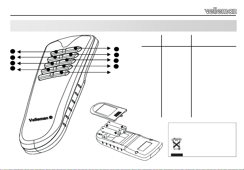
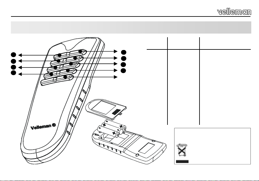
KEYBOARD LAYOUT
Output
channel
1
3
5
7
2
4
6
8
SHIFT
Output channe l
with 'SHIFT'
1 9 Mute
2 10 Power
3 11 Volume up
4 12 Preset up
5 13 Volume down
6 14 Preset down
7 15 Source
8 All clear Tuner seek
Insert the batteries in the battery compartment as indicated in the figure and close
the compartment.
Compatible with our
tuners/preamps & kits
Remark : Respect your national
and local laws when disp os ing of
empty batteries.
4
Page 5

MODE SELECTION
At first power up, Address 3 is automatically selected.
Press and hold SHIFT to change mode. Led starts flashing.
Press button 1..8 to select desired mode as shown below.
Hint : When the batteries are inserted, the led flashes 1..4 times indicating the selected mode.
Key Description
Address '1'
1
3
4
5
7
8
Address '2'
Address '3'
Address '4'
Address '5'
Address '6'
Address '7'
Address '8'
15 channels available ('shift' & '8' = all clear). Shift is cleared after each key press 2
Allows simultaneous control of K4100/K4500 and VM122 (only channels 1 to 8 using
6
shift key).
Identical to address 1 to 3 but ‘shift’ is not cleared after each key press.
Identical to address 4 but ‘shift’ is not cleared after each key press.
Mode selection
5
Page 6

Use
USE
To access channel 1..8 :
Press button for channel 1..8.
Holding the button will result in continuous transmission, led will flash indicating transmission.
To access channel 9..15 :
Briefly press 'shift'. Led will light indicating that 'shift' has been pressed.
Press button 1..8 to access channel 9..15
Holding the button will result in continuous transmission.
If no button is pressed after 'shift' has been pressed, the 'shift'-led will turn off in about 10s, hereby cancelling the 'shift'selection.
Pressing 'shift' repeatedly toggles between shift-on and shift-off
6
.
Page 7
Safety & warning instructions
WARNINGS
All repairs should be executed by qual ified te chnicians.
SAFETY INSTRUCTIONS
Handle the module gently and carefully. Dropping it can damage the circuit board.
Never exceed the protection limit values indicated in the specifications.
As safety requirement vary, please check with your local authorities.
Fac ilita te t he op era tion of t he de vic e by f am iliaris in g y our self wit h its adj ustm en ts a nd in dic at ions.
Velleman modules are not suitable for use or as part of life support systems, or systems that might create hazardous situations of kind.
Repair under warranty is only poss ible with dat e and p roof of pu rchase .
7
Page 8

Waarschuwingen en inhoud
Hartelijk dank voor de aanschaf van deze IR zender. Lees de gebr uiksaanwijzing aandachtig, zodat u het a pparaat op de
juiste manier gebruikt.
WAARBORG
Dit produkt is gewaarborgd wat betreft gebreken in materialen en vakmanschap op het ogenblik van de aankoop en dit gedurende een periode van TWEE
JAAR vanaf de aankoop. De waarborg geldt enkel indien het produkt voorgelegd wordt samen met het origineel aankoop bewijs. De verplichtingen van
VELLEMAN COMPONENTS N.V. beperken zich tot het herstellen van defecten of, naar vrije keuze van VELLEMAN COMPONENTS N.V., tot het vervangen of
herstellen van defecte onderdelen. Kosten en risico’s van transport; het wegnemen en terugplaatsen van het produkt, evenals om het even welke andere
kosten die re chtstreeks of onrechtstre eks verband houden met de hers telling, worden niet door V ELLEMAN COMPONENTS N.V. ve rgoed. VELLEMAN
COMPONENTS N.V. is niet verantwoordelijk voor schade van gelijk welke aard, veroorzaakt door het falen van een product.
CONTENTS
LEES DE GEBRUIKS - EN ONDERHOUDSAANWIJZINGEN VAN DE
HANDLEIDI NG Z OR GV U LD IG D OO R .
KENMERKEN & SPECIFICATIES................................................................................................................................................................. 10
TOETSENBORD INDELING .......................................................................................................................................................................... 11
MODE SELECTIE ............................................................................................................................................................................................12
GEBRUIK...........................................................................................................................................................................................................13
VEILIIGHEIDSAANWIJZINGEN EN WAARSCHUWINGEN .....................................................................................................................14
8
Page 9

EIGENSCHAPPEN & TECHNISCHE GEGEVENS
EIGENSCHAPPEN
Combineerbaar met onze ontvangstmodule VM122.
3 adressen laten u toe om meerdere ontvangers te gebru iken in zelfde ruimte
Ergonomisch design voor extra comfort.
LED functie weergave
Rubberen toetsenpan eel
TECHNISCHE GEGEVENS
Voeding: 3 x 1.5V AAA batterijen
Tot 15 kanalen bedienbaar
Bereik zender – ontvanger: tot 20m
Afmetingen : 150 x 58 x 22mm / 5,9 x 2,3 x 0,86”
Eigenschappen en technische gegevens
9
Page 10
Toetsenbord indeling
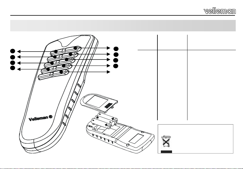
INDELING VAN HET TOETSENBORD
1
3
5
7
10
2
4
6
8
SHIFT
Uitgangs
kanaal
Uitgangskanaal
met 'SHIFT'
1 9
2 10
3 11
4 12
5 13
6 14
7 15
8 All clear
Plaats drie AAA batte rijen in de batte ri jhou der
zoals aangegeven in de tekening !
Compatibel met onze tuners/
Toestel in/uitschakelen
Geluidsterkte verhogen
Geluidsterkte verlagen
Volgend station zoeken
Opmerking : Respecteer de nationale
en lokale wetten wanneer u lege
batterijen weggooit.
voorversterkers en kits
‚Mute’-toets.
Volgende preselectie
Vorige preselectie
Bron
Page 11

Mode selectie
MODE SELECTIE
Bij de eerste gebruikname w ord t adr es 3 automatisch geselecteerd.
Houd de SHIFT knop ingedrukt (de LED begint te knipperen).
Druk nu op één van de toetsen 1 ... 8 om een functie te kiezen zoals hieronder wordt uitgelegd.
TIP : wanneer de batterijen in de batterijhouder zijn geplaatst, knippert de LED 1 tot 4 maal naargelang de gekozen functie.
Toets Omschrijving
Adres '1'
1
Adres '2'
2
Adres '3'
3
Adres '4'
4
Adres '5'
5
Adres '6'
6
Adres '7'
7
Adres '8'
8
(15 kanalen zijn beschikbaar (Shift & toets 8 = alles wissen). De shift toets wordt na
iedere bewerking autom atisch weer uitgeschak el d.
Maakt het mogelijk om de K4100/K4500 en de VM122 gelijktijdig te gebruiken.
(Gebruikt de 'shift' toets voor kanaal 1 tot 8)
Idem als adres 1 tot adres 3 maar de 'Shift’ toets blijft geactiveerd na een toetsdruk
Idem als adres 4 maar de 'Shift’ toets blijft geactiveerd na een toetsdruk
11
Page 12

Gebruik
GEBRUIK
Selecteren van kanaal 1 ... 8 :
Druk op één v/d toetsen 1 ... 8 om een kanaal van 1 tot 8 te selecteren.
Hou deze toets ingedrukt voor een ononderbroken transmissie. De LED knippert ter bevestiging van de transmissie.
Selecteren van kanaal 9 ... 15
:
Druk op de ‚shift’ toets. De LED geeft aan dat de shift-functie is gekozen.
Druk op één v/d toetsen 1 ... 8 om een kanaal van 9 tot 15 te selecteren.
Hou deze toets ingedrukt voor een ononderbroken transmissie. De LED knippert ter bevestiging van de transmissie.
De shift funtie en de LED worden uitgeschakeld indien u na het indrukken van de 'shift' toets gedurende 10 seconden
geen enkele andere toets indrukt.
De 'shift' functie wisselt af tussen ON en OFF telkens u de knop indrukt
12
.
Page 13

Veiligheidsaanwijzingen en waarschuwingen
WAARSCHUWING
Reparaties mogen uitsluitend uitgevoerd worden door vakkundige personen.
VEILIGHEIDSAANWIJZINGEN
Vermijd een ruwe behandeling. Stoten of laten vallen kunnen ernstige schade aanbrengen.
Overschrijdt nooit de opgegeven veiligheidswaarden in de specificaties.
Vermits de veiligheid vereisten vers chillen van plaats tot plaats, dient U ervoor te zorgen dat Uw montage voldoet aan de plaatselijke geldende
vereisten.
Zorgt ervoor dat u met alle bedieningselementen vertrouwd raakt, wanneer U met het toestel zal werken.
Velleman modules zijn niet geschikt voor gebrui k in of als gedeelte van systemen wel ke levensfuncties in stand houden of systemen welke
gevaarlijke situaties van gelijk welke aard kunnen veroorzaken.
Herstelling onder garantie is enk el mogeli jk me t aan koopbewijs .
13
Page 14

Avertissements et sommaire
Merci d'avoir choisi cet émett eu r IR. Lisez attentivement le mode d’emploi de façon à utiliser l’appareil de manière adéquate.
GARANTIE
Ce produit est garanti contre les défauts des composantes et de fabrication au moment de l’achat, et ce pour une période dE TROIS AN à partir de la date
d’achat. Cette garantie est uniquement valable si le produit est accompagné de la preuve d’achat originale. Les obligations de VELLEMAN COMPONENTS
S.A. . se limitent à la réparation des défauts ou, sur seule décision de VELLEMAN COMPONENTS S.A. au remplacement ou à la réparation des pièces
défectueuses. Les frais et les risques de transport, l’enlèvement et le renvoi du produit, ainsi que tous autres frais liés directement ou indirectement à la
réparation, ne sont pas pr i s en c har g e par VELLEMAN COMPONEN TS S.A.
VELLEMAN COMPONENTS S.A. n’est pas responsable des dégâts, quels qu’ils soient, provoqués par le mauvais fonctionnement d’un produit.
CONTENTS :
LIRE ATTENTIVEMENT LES INSTRUCTIONS DE SERVICE ET DE
MAINTENANCE DU PRESENT MANUEL..
CARACTERISTIQUES & DONNEES TECHNIQUES ................................................................................................................................ 16
COMPOSITION DU CLAVIER ....................................................................................................................................................................... 17
MODE SELECTION......................................................................................................................................................................................... 18
EMPLOI.............................................................................................................................................................................................................. 19
CONSIGNES DE SECURITE ET MISES EN GARDE ............................................................................................................................... 20
14
Page 15

CARACTERISTIQUES ET DONNEES TECHNIQUES
DONNEES TECHNIQUES
Peut être combiné avec notre module récepteur VM122.
3 adresses permettent l'emploi de plusieurs récepteurs dans la même pièce.
Design ergonomique pour un meilleur confort
LED témoin de fonction.
Clavier en caoutchouc.
SPECIFICATIONS :
Alimentation : 3 piles AAA (1,5V)
Sélectionnez un des 15 canaux
Portée émetteur – récepteur: jusq u'à 2 0m
Dimensions: 150 x 58 x 22mm / 5,9 x 2,3 x 0,86“
Caractéristiques et données techniques
15
Page 16

Composition du clavier
COMPOSITION DU CLAVIER
1
3
5
7
16
2
2
4
6
8
SHIFT
(canal de)
(canal de) sortie
sortie
à commande
'SHIFT'
1 9 Bouton ‚Mute’
2 10 Fonction marche/arrêt
3 11 Augmenter le volum e
4 12
5 13 Diminuer le volume
6 14 Preset down
7 15 Source
8 All clear Chercher le prochain post e
Insérez trois piles LR3 dans le compartiment des
piles avant l'usage!
.
Remarque : Respectez les lo is n at io na le s
et locales quand vous jetez vos p iles
usées.
compatible avec nos
tuners/préamplificateurs et
kits
Choisir le prochain
préselection
Page 17

Selection du mode
SELECTION DU MODE
Adresse 3 est automatiquement instauré lors de la mise en service.
Maintenez le bouton SHIFT enfoncé. Une LED commencera à clignoter.
Pressez alors une des touches 1 ... 8 pour choisir une fonction (voi r ci -de sso u s).
ASTUCE : quand les piles ont été installées dans le porte-piles, la LED clignotera 1 à 4 fois selon la fonction sélectionnée.
Touche Description
1
2
3
4
5
6
7
8
Adresse '1'
Adresse '2'
Adresse '3'
Adresse '4'
Adresse '5'
Adresse '6'
Adresse '7'
Adresse '8'
15 canaux sont disponibles (Shift & touche 8 = effacer tout). La touche shift est désactivée après chaque opération.
Permet d'utiliser les kits K4100/K4500 et VM122 en même temps. sélectionnez canal 1
à 8 en utilisant le bouton 'shift'
Voir adresses 1 à 3 mais la touche 'shift' reste active après une opération
Voir adresse 4 mais la touche 'shift' reste active après une opération
17
Page 18

Emploi
EMPLOI
Sélectionner canal 1 ... 8 :
Pressez une des touches 1 ... 8 pour sél ecti on ner un canal de 1 à 8.
Gardez cette touche enfoncée pour une transmission continue. La LED clignote pour confirmer la transmission.
Sélectionner canal 9 ... 15 :
Pressez 'shift' momentanément. La LED indiquer que la fonction shift a été sélectionnée.
Pressez une des touches 1 ... 8 pour sél ecti on ner un canal de 1 à 15.
Gardez cette touche enfoncée pour une transmission continue. La LED clignote pour confirmer la transmission.
La LED et la fonction 'shift' sont désactivées si aucune touche n'est pressée pendant 10 secondes.
La fonction shift alterne entre ON et OFF chaque fois que la touche 'shift' est pressée.
18
Page 19

Consignes de sécurité et mises en garde
AVERTISSEMENT
All repairs should be ex ecuted by qualif ied te chnicians. Toute répa ration doi t être exécuté e par du personnel qualifié .
SAFETY INSTRUCTIONS
Evitez les manipulations brutales. Un chute pourrait endommager le boîtier ou les plaque et pourrait causer des défauts.
Ne jamais excéder les valeurs limites de protection indiqué es dans les spécificat ions.
Etant donné que les exigences en matière de sécurité varient d’un lieu à l’autre, vous devez vous assurer que votre montage satisfait aux exigences.
Familiarisez- vous ave c tou s les r églages et indications de l'appareil afin de faciliter l'opération.
Les modules Velleman ne conviennent pas pour une utilisation dans ou comme parties de systèmes servant à assurer des fonctions de survie ou des
systèmes pouvant entraîner des situations dangereuses, de quelque nature qu‘elles soient.
La réparation sous garanie est un iquement poss ible av ec la preuv e de l‘achat !
19
Page 20

Warnungen und inhalt
Danke für den Kauf dies es IR-Fernbe dienungs senders. Lese n Sie Bitte aufm erksam die Bedi enunggs anleitung, s o dass sie
das Gerät richtig benutzen.
GARANTIE
Dieses Produkt trägt eine Garantie für fehlerhaftes Material oder Verarbeitungsschäden im Moment des Ankaufs. Sie ist ZWEI JAHR gültig ab Ankaufsdatum.
Die Garantie kann nur beansprucht werden, wenn das Produtk mit der Originalrechnung abgegeben wird. Die Verpflichtungen der VELLEMAN
COMPONENTS AG beschränken sich auf die Aufhebung der Fehler, oder, nach freier Wahl der VELLEMAN COMPONENTS AG , auf den Austausch oder die
Reparation der fehlerhaften Teile. Kosten und Risiken des Transports; das Entfernen und Wiedereinsetzen des Produkts, sowie alle anderen Kosten die direkt
oder indirekt mit der Reparation in Verbindung gebracht werden können, werden durch die VELLEMAN COMPONENTS AG nicht zurückerstattet. VELLEMAN
COMPONENTS AG ist nicht für Sc hä de n gl eic h w elc her Ar t, en tsta nd en aus der fehlerhaften Funktion des Produkt, haftbar .
INHALT :
LESSEN SIE DIE BETRIEBS– UND WARTUNGSANWEISUNGEN
DIESES HA ND BU CH S SO R GF ÄL TI G D URC H .
SPEZIFIKATIONEN UND TECHNISCHE KENNDATEN........................................................................................................................... 22
EINTEILUNG DER TASTATUR .................................................................................................................................................................... 23
MODUS-AUSWAHL......................................................................................................................................................................................... 24
GEBRAUCH...................................................................................................................................................................................................... 25
SICHERHEITS– UND WARNHINWEISE..................................................................................................................................................... 26
20
Page 21

Spezifikationen und Technische kenndaten
SPEZIFIKATIONEN & TECHNISCHE DATEN
SPEZIFIKATIONEN :
Funktioniert zusammen mit dem Empfangsmodul VM122.
3 Adressen ermöglichen Ihnen, verschiedene Empfänger in demselben Raum zu verwenden.
Egonomischer Entwurf für mehr Komfort
Funktion-LED.
Gummitastatur.
TECHNISCHE DATEN :
Versorgung: 3 x 1,5V AAA-Batterien
Bis zu 15 Kanälen bedienbar.
Reichweite Sender - Empfänger: bis zu 20m
Abmessungen : 150 x 58 x 22mm / 5,9 x 2,3 x 0,86“
21
Page 22

Einteilung
EINTEILUNG DER TASTATUR
1
3
5
7
22
2
4
6
8
SHIFT
Ausgangs-
Ausgangskanal
kanal
mit ‘SHIFT’-
Bedienung
1 9 Mute'-Taste
2 10 Ein-/ausschalten des Geräts
3 11 Lautstärke erhöhen
4 12 Nächste Vorwahl
5 13 Lautstärke mindern
6 14 Vorige Vorwahl
7 15 Quelle
8 All clear
Legen Sie vor Gebra uch 3 x AAA-Batterien in
das Batteriefach ein.
Kompatibel mit unseren
Tunern / Vorverstärkern
und Bausätzen
Zum Wählen eines anderen
Senders
Anmerkung: Entsorgen Sie die leeren
Batterien den nationa len und ör t l ichen
Gesetzen entsprechend
Page 23

Modus-auswahl
MODUS-AUSWAHL
Bei dem ersten Betrieb wird automatisch Adresse 3 selektiert.
Drücken Sie auf SHIFT und halten Sie diese Taste eingedrückt. Eine LED wird blinken.
Drücken Sie jetzt auf eine der Tasten 1…15 um eine Funktion zu wählen (siehe unten).
HINWEIS: wenn die Batterien eingelegt worden sind, wird die LED 1 bis 4 Mal blinken um die gewählte Funktion anzuzeigen.
Taste Umschreibung
1
2
3
4
5
7
8
Adresse '1'
Adresse '2'
Adresse '3'
Adresse '4'
Adresse '5'
Adresse '6'
Adresse '7'
Adresse '8'
15 Kanäle sind verfügbar (Shift & Taste 8 = alles löschen). Die Shift-Taste wird nach
jedem Tastendruck ausgeschaltet.
Ermöglicht Ihnen, K4100/K4500 und VM122 zur gleic he n Zeit zu v er wen de n.
(Verwenden Sie die ‘Schift’-Taste um Kanal 1 bis 8 auszuwählen).
Dasselbe wie Adresse 1 bis Adresse 3 aber die 'Shift'-Taste bleibt aktiv nach einem
6
Tastendruck.
Dasselbe wie Adresse 4 aber die 'Shift'-Taste bleibt aktiv nach einem Tastendruck.
23
Page 24

Gebrauch
GEBRAUCH
To access channel 1..8 :
Drücken Sie auf eine der Tasten 1 ... 8 um einen Kanal von 1 bis 8 auszuwählen.
Halten Sie diese Taste eingedrückt. So verursachen Sie eine ununterbrochene Übertragung. Die LED blinkt als Anzeige
der Übertragung.
To access channel 9..15 :
Drücken Sie kurz auf die 'Shift'-Taste. Die LED zeigt an, dass die 'Shift'-Funktion gewählt wurde.
Drücken Sie auf eine der Tasten 1... 8 um einen Kanal von 1 bis 15 zu auswählen.
Halten Sie diese Taste eingedrückt. So verursachen Sie eine ununterbrochene Übertragung. Die LED blinkt als Anzeige
der Übertragung.
Wenn 10 Sekunden nach dem E indrü ck en de r 'Shif t'-Tas te auf k ein e and ere Taste g edrück t wir d, wer den di e 'Shif t'-Fu nk tion
und die LED-Anzeige ausgeschaltet.
Wenn Sie verschiedene Male auf die 'Shift'-Taste drücken, können Sie zwischen EIN/AUS der 'Shift'-Funktion wählen
24
Page 25

Sicherheits– und W arnhin w eise
WARNUNG
Lassen Sie Reparaturen dur ch Fachl eute er folgen
SICHERHEITSHINWEISE
Gehen Sie behutsam mit dem Modul um. Es fallen lassen, kann die Leiterplatte und das Gehäuse beschädigen.
Überschreiten Sie nie die in den technischen Daten erwähnten Eingangsgrößen.
Sicherheitsvorschriften können sich ändern, bitte beachten Sie die lokalen Vorschriften Ihres Landes.
Machen Sie sich mit allen Bedienungselement vertraut, wenn Sie mit diesem Gerät arbeiten.
Der von Ihnen gekaufte Bausatz ist aber für den Privatgebrauch konzipiert und nich für den Einsatz in Lebenserhaltenden oder
Lebensrettenden Systemen oder unter außergewöhnlichen Umweltbedingungen (Ex-systeme) geeinet.
Reparatur unter Garantiebedingungen ist nu r be i Vo rlage des Kaufbe leges möglich.
25
Page 26

Advertencias y contenido
¡Gracias por haber comprado este emisor IR! Lea cuidadosamente todas las instrucciones antes de usar el
dispositivo.
GARANTÍA
Este producto está garantizado contra defectos de componentes y construcción a partir de su adquisición y durante un período de TRES AÑO a partir de la
fecha de venta. Esta garantía sólo es válida si la unidad se entrega junto con la factura de compra original. VELLEMAN COMPONENTS Ltd. limita su
responsabilidad a la reparación de los defectos o, si VELLEMAN COMPONENTS Ltd. lo estima necesario, a la sustitución o reparación de los componentes
defectuosos. Los gastos y riesgos con respecto al transporte, el desmontaje o la instalación del dispositivo, o cualquier otro gasto directa o indirect amente
vinculado con la reparación, no será reembolsado por VELLEMAN COMPONENTS Ltd. VELLEMAN COMPONENTS Ltd no responderá de ningún daño
causado por el mal funcionamiento de la unidad.
CONTENIDO :
CARACTERÍSTICAS & ESPECIFICACIONES ........................................................................................................................................... 40
OPCIONES ....................................................................................................................................................................................................... 41
CONEXIONES..................................................................................................................................................................................................42
EFECTO LUMINOSO...................................................................................................................................................................................... 44
SEGURIDAD Y AVISOS .................................................................................................................................................................................46
LEA ESTE MANUAL EN SU TOTALIDAD Y SIGA CUIDADOSAMENTE
LAS INSTRUCCIONES DE MANTENIMIENTO.
26
Page 27

ESPECIFICARTIONES Y CARACTERÍSTICAS
ESPECIFICACIONES :
Funciona con nuestro receptor VM122
3 direcciones le permiten usar varios receptores en el mismo lugar.
diseño ergonómico para un mejor confort.
LED piloto de función.
Teclado de goma.
CARACTERÍSTICAS :
Alimentación : 3 pilas AAA (1,5V)
Seleccione uno de los 15 canales.
Rango emisor - receptor: máx. 20m
Dimensiones: 150 x 58 x 22mm / 5,9 x 2,3 x 0,86“
Especificaciones y Características
27
Page 28
División del teclado
DIVISIÓN DEL TECLADO
1
3
5
7
28
2
4
6
8
SHIFT
Canal de
Canal de salida
salida
con operación
'SHIFT'
1 9 Amortiguar el sonido
2 10 Activar/desactivar el aparato
3 11 Aumentar el volumen
4 12 Seleccionar otro estación
5 13 Bajar el volumen
6 14
7 15 Fuente
8 All clear Buscar la siguiente estación
¡Introduzca tres pil as AAA en el comparti miento de baterías antes del uso!
Compatible con nuestros
sintonizadores/ pr eam pl ifi-
cadores y kits
Seleccionar el estación
anterior
Observación : Respete las leyes
nacionales y locales al tirar pilas
agotadas.
Page 29

Modo selección
MODO SELECCIÓN
Se selecciona el dirección 3 automáticamente durante la primera puesta en marcha
Mantenga apretado el botón SHIFT. Empieza a parpadear 1 LED.
Ahora, apriete uno de los botones 1 ... 8 para seleccionar una función (véase abajo).
CONSEJO : Después de haber introducido las pilas, el LED parpadea de 1 a 4 veces según la función seleccionada.
Descripción
Botón
Dirección '1'
1
Están disponibles 15 canales (Shift & botón 8 = borrar todo). Se desactiva el botón
2
3
4
5
7
8
Dirección '2'
Dirección '3'
Dirección '4'
Dirección '5'
Dirección '6'
Dirección '7'
Dirección '8'
shift después de cada operación.
Permite usar los kits K4100/K4500 y el VM122 al mismo tiempo. (Seleccione canal 1
a 8 con el botón ‘shift’).
Véase dirección 1 a dirección3 pero el botón 'shift' queda activo después de una
6
operación
Véase que dirección 4 pero el botón 'shift' queda activo después de una operación
29
Page 30

Uso
USO
Seleccionar canal 1 ... 8 :
Apriete uno de los botones 1 ... 8 para selecci on ar un can al de 1 a 8.
Mantenga apretado este botón para una transmisión ininterrumpida. El LED parpadea para confirmar la transmisión.
Seleccionar canal 9 ... 15 :
Apriete el botón ‚shift’ brevemente. El LED indicar que se ha seleccionado la función shift.
Apriete uno de los botones 1 ... 8 para selecci on ar un can al de 1 a 15.
Mantenga apretado este botón para una transmisión ininterrumpida. El LED parpadea para confirmar la transmisión.
El LED y la función 'shift' se desactivan si no se apriete ningún botón durante 10 segundos.
La función shift alterna entre ON y OFF cada vez que se apriete 'shift'
30
Page 31

Seguridad y avisos
AVISOS
El servicio debe ser realizado por personal especializado
LAS MEDIDAS DE SEGURIDAD
Manéjese con cuidado. Dejar caer el dispositivo puede dañar el circuito impreso y la caja.
Nunca exceda los valores límites indicados en las especificaciones.
Las exigencias en materia de seguridad varían de un lugar a otro. Asegúrese que el montaje realizado sea conforme a las exigencias
en vigor de su localidad.
Siga cuidadosamente todas las instrucciones y familiarícese con los ajustes al operar este dispositivo.
Los modulo Velleman no son adecuados para una utilización dentro o corno sistema destinado a garantizar funciones para sobrevivir o
sistemas conllevando situaciones peligrosas sea cual su naturaleza.
La reparación en garantí a só lo es pos ibl e con e l t icket y la fe cha d e co mpra .
31
Page 32

15 CHANNEL IR TRANSMITT ER
15 CHANNEL IR TRANSMITT ER
VM121
USER MANUAL
Belgium [Head office] Velleman Components +32(0)9 384 36 11
France Velleman Electronique +33(0)3 20 15 86 15
Netherlands Velleman Components +31(0)76 514 7563
USA Velleman Inc. +1(817)284-7785
Spain Velleman Components +32(0)9 384 36 11
15 CHANNEL IR TRANSMITT ER
5410 329 333393
Modifications and typographical errors reserved - © Velleman Components nv - HVM121G - 2005 - ED1
 Loading...