

Page 1
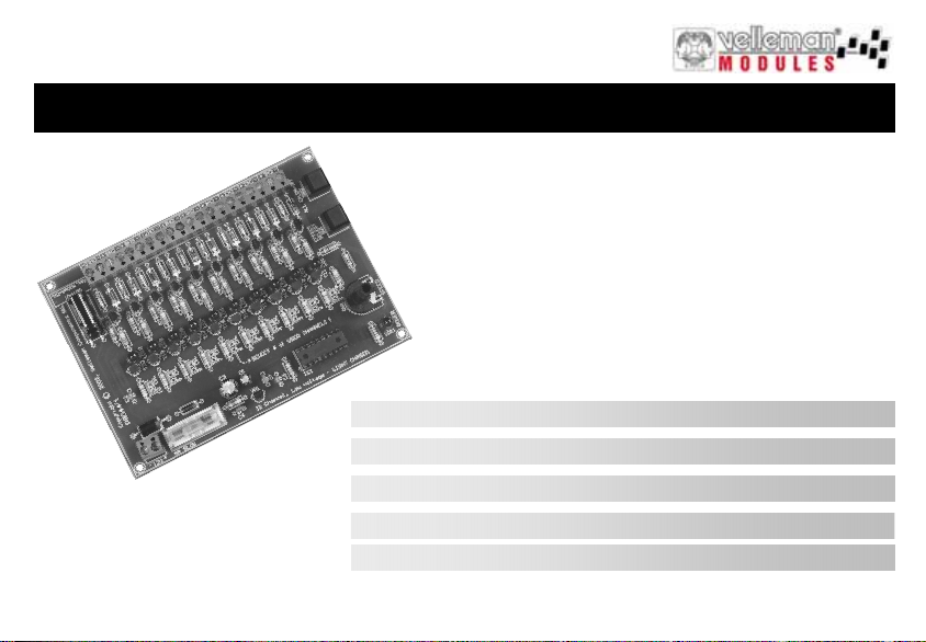
12V LIGHT EFFECT GENERATOR
VM120
12V light effect generator 3
12V tien kanaals lichteffect generator 12
Générateur d’effets lumineux à 10 canaux, 12V 21
10-Kanal-Lichteffektgenerator, 12V 30
Generador de efectos luminosos de 10 canales, 12V 39
Page 2

Page 3
Warnings and contents
Thank you for purchasing this module. Please read the instructions carefully to ensure correct and safe use of this device.
WARRANTY
This product is guaranteed against defects in components and construction from the moment it is purchased and for a period of ONE YEAR starting from the
date of sale. This guarantee is only valid if the unit is submitted together with the original purchase invoice. VELLEMAN components Ltd limits its responsibi-
lity to the reparation of defects or, as VELLEMAN components Ltd deems necessary, to the replacement or reparation of defective components. Costs and
risks connected to the transport, removal or placement of the product, or any other costs directly or indirectly connected to the repair, will not be reimbursed by
VELLEMAN components Ltd. VELLEMAN components Ltd will not be held responsible for any damages caused by the malfunctioning of a unit.
CONTENTS :
READ THE OPERATING AND MAINTENANCE INSTRUCTIONS IN
THIS USER’S GUIDE CAREFULLY.
FEATURES & SPECIFIC ATION S...................................................................................................... ...................................................4
OPTIONS ..............................................................................................................................................................................................5
CONNECTION.......................................................................................................................................................................................6
LIGHT EFFECTS .................................................................................................................................................................................. 8
SAFETY & WARNING INSTRUCTIONS............................................................................................................................................ 11
3
Page 4

Specifications & features
SPECIFICATIONS & FEATURES
FEATURES
Ten, 12V/400mA outputs
To control cold-cathode fluorescent lamps (using FLPS adapter), light bulbs, LED’s and “solid state” relays, ...
For use as advertisement lighting, party lights, disco, eye-catcher, ...
Ten pre-programmed light patterns selectable with a push button.
The number of used channels is adjustable.
Non volatile memory for last used light effect
Adjustable speed
LED indication for every output.
12V operation possible for use in cars.
SPECIFICATIONS
Power supply : 12V DC
Outputs : 12V DC/400mA per channel (Total : max 4A)
Dimensions : 140 x 100 x 27mm / 5,5 x 3,9 x 1,1”
4
Page 5
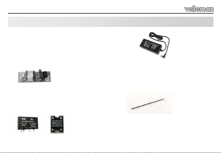
OPTIONS
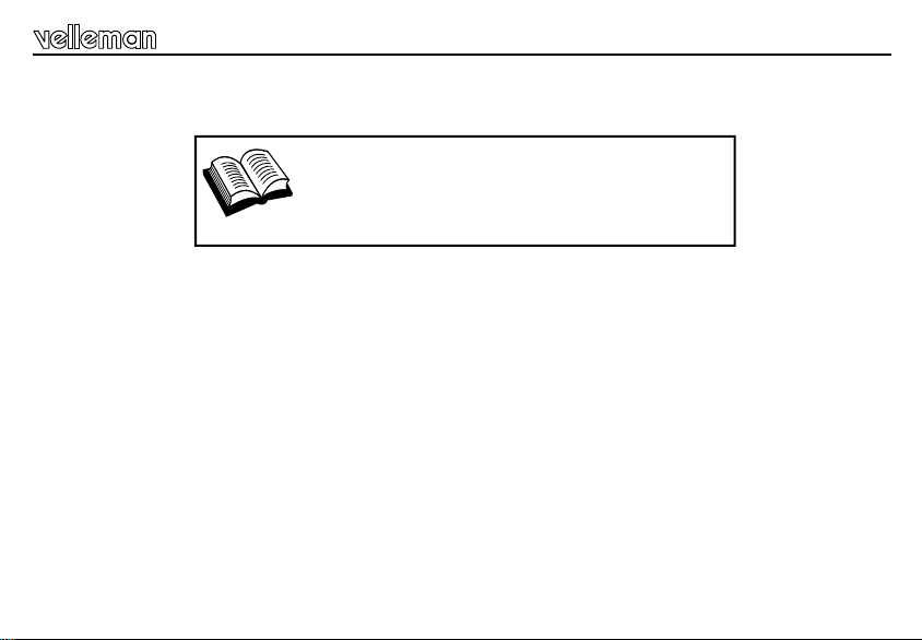
Supply adaptor 12V output 5.5A: PSS1255
Cut off the connector, determine the adapter's polarity and connect the
adapter to the module. RESPECT THE POLARITY!!!
Cold-cathode fluorescent lamps : FL(xx) – (100 or 300mm)
Power supply for cold-cathode fluorescent lamps : FLPS (300mm) or FLPS1 (100mm)
SOLID-STATE relays VR25SS1A or VR3SS1A to drive mains voltage lamps
VR25SS1A VR3SS1A
Options
5
Page 6
Connection
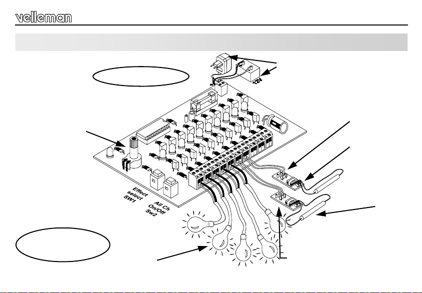
CONNECTION
a
d
e
e
p
S
12VDC/400mA per
channel
6
12VDC / max 4A
t
s
u
j
d
12V bulb
400mA max.
OR !
Inverter FLPS
T
U
P
N
I
V
2
1
H
!
G
E
I
G
H
A
T
L
O
V
Cold-cathode
fluorescent lamps
Page 7

Connection
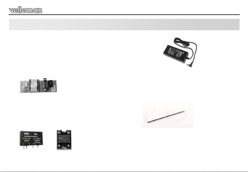
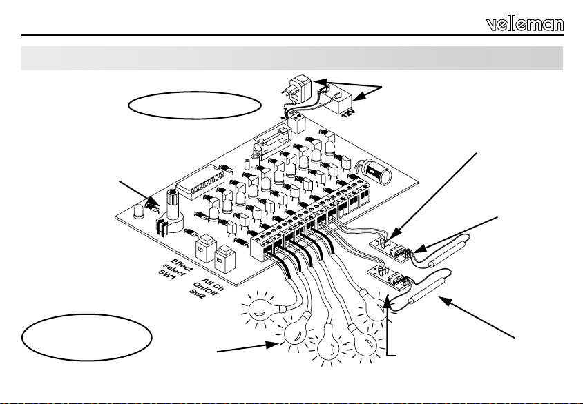
Connect this module according to the connection diagram:
Connect a 12V DC power supply to the – 12 + connections. Respect the polarity! When polarity is reversed, the fuse will
blow.
Up to 10 loads can be connected to the outputs. These can be small lamps, relays or cold-cathode fluorescent lamps. The
current in each separate channel cannot surpass 400mA. Respect the polarity!
When a correct power supply is connected, LED LD1 will light up. All 10 red LEDs will already display a light effect .
Be careful when connecting the cold cathode fluorescent lamps: the ‘FLPS1’ power supply module generates a
life-threatening voltage over the lamp connectors, which may cause electroshocks.
Settings:
Before switching on the module, set the jumper to indicate how many lamps are connected.
For example : to make a 4-channel running light, set the jumper to ‘4 CH’.
If the module is powered on without the jumper, the 10 channels will flash simultaneously ; this way the module can be used
as a 10-channel flashing light with adjustable speed.
7
Page 8

Light effects
LIGHT EFFECTS
Choosing light effects :
The SW1 ‘Effect select’ pushbutton switch allows you to choose between ten programs. Keep SW1 pressed to see the selected effect – the LED corresponding to that effect will light up. The effect starts when you release SW1. Press SW1 briefly
to select the next effect.
SW2 allows you to (de)activate all channels at once. Press SW1 to restart the selected light effect.
The speed of the light effect can be adjusted with RV1.
The last selected effect is saved in the internal memory in case of a power failure.
Select a random light effect:
Keep SW2 pressed during power-up (the other light effects will not work!).
HINTS:
• In case of an overload or a short circuit on one of the outputs, the control transistor of that channel (T1...T10) will be
damaged. Replace it by a transistor of the same type (BC640).
• Velleman cannot be held responsible and all warranty becomes void in case of user modifications to the module.
• A blown fuse always has to be replaced by a fuse of the same type (4A – FAST) to avoid fire hazard.
8
Page 9
L
LLL
L
Light effects
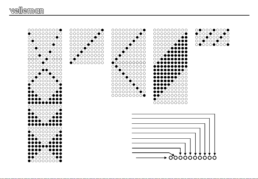
Light effect 1 Light effect 2 Light effect 3 Light effect 4 Light effect 5
LED 1 / CHANNEL 1
LED 2 / CHANNEL 2
LED 3 / CHANNEL 3
LED 4 / CHANNEL 4
LED 5 / CHANNEL 5
LED 6 / CHANNEL 6
LED 7 / CHANNEL 7
LED 8 / CHANNEL 8
LED 9 / CHANNEL 9
LED 10 / CHANNEL 10
9
Page 10
L
L
Light effects
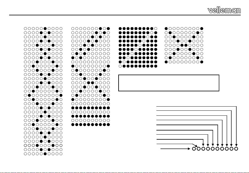
Light effect 6 Light effect 7 Light effect 8 Light effect 9
Light effect 10 is a sequence of light effects 1
to 9, each played 5 times.
LED 1 / CHANNEL 1
LED 2 / CHANNEL 2
LED 3 / CHANNEL 3
LED 4 / CHANNEL 4
LED 5 / CHANNEL 5
LED 6 / CHANNEL 6
LED 7 / CHANNEL 7
LED 8 / CHANNEL 8
LED 9 / CHANNEL 9
LED 10 / CHANNEL 10
10
Page 11

Safety & warning instructions
WARNINGS
All repairs should be executed by qualified techn icians.
Avoid the installation of the module in l ocations with standing or r unning water or excessiv e humidity. Indo or use o nly !
SAFETY INSTRUCTIONS
Handle the module gently and carefully. Dropping it can damage the circuit board.
Never exceed the protection limit values indicated in the specifications.
As safety requirement vary , plea se c heck w ith y our l ocal auth oriti es.
Keep the device away fro m childr en.
Facilitate the operation of the device by familiarising yourself with its adjustments and indications.
Velleman modules are not suitable for use or as part of life support systems, or systems that might create hazardous situations of kind.
Repair under warranty is only possible with date and proof o f purchase .
11
Page 12
Waarschuwingen en inhoud
Hartelijk dank voor de aanschaf van deze module. Lees de gebruiksaanwijzing aandachtig, zodat u het apparaat op de juiste
manier gebruikt.
WAARBORG
Dit produkt is gewaarborgd wat betreft gebreken in materialen en vakmanschap op het ogenblik van de aankoop en dit gedurende een periode van EEN JAAR
vanaf de aankoop. De waarborg geldt enkel indien het produkt voorgelegd wordt samen met het origineel aankoop bewijs. De verplichtingen van
VELLEMAN COMPONENTS N.V. beperken zich tot het herstellen van defecten of, naar vrije keuze van VELLEMAN COMPONENTS N.V., tot het vervangen
of herstellen van defecte onderdelen. Kosten en risico’s van transport; het wegnemen en terugplaatsen van het produkt, evenals om het even welke andere
kosten die rechtstreeks of onrechtstreeks verband houden met de herstelling, worden niet door VELLEMAN COMPONENTS N.V. vergoed. VELLEMAN
COMPONENTS N.V. is niet verantwoordelijk voor schade van gelijk welke aard, veroorzaakt door het falen van een product.
CONTENTS
LEES DE GEBRUIKS - EN ONDERHOUDSAANWIJZINGEN VAN DE
HANDLEIDING ZORGVULDIG DOOR.
KENMERKEN & SPECIF ICAT IES......................................................................................................................................................13
OPTIE‘S...............................................................................................................................................................................................14
AANSLUITING..................................................................................................................................................................................... 15
LICHT EFFECTEN..............................................................................................................................................................................17
VEILIIGHEIDSAANWI JZ INGEN EN WA ARSCH U WIN GEN............................................................................................................. 20
12
Page 13

Eigenschappen en technische gegevens
EIGENSCHAPPEN & TECHNISCHE GEGEVENS
EIGENSCHAPPEN
Tien 12V / 400mA uitgangen.
Voor het aansturen van koude kathode fluo lampen (via een FLPS adapter), gloeilampjes, LEDs, “solid state”-relais.…
Voor gebruik bij lichtreclames, feestverlichting, in discotheken, als aandachttrekker...
10 voorgeprogrammeerde lichtpatronen, selecteerbaar d.m.v. een drukknop.
Het laatst gebruikte lichteffect wordt bewaard in een niet-vluchtig geheugen.
Het aantal gebruikte kanalen is instelbaar.
Regelbare snelheid.
Controle LED per uitgang.
Gebruik in de wagen mogelijk (12V).
TECHNISCHE GEGEVENS
Voedingsspanning: 12Vdc.
Uitgangen: 12Vdc / 400mA per kanaal (totaal max. 4A).
Afmetingen print: 140 x 100 x 27 mm. (5,5” x 3,9” x 1,1”).
13
Page 14
Optie’s
OPTIE’S
Adapter 12V uitgang 5.5A: PSS1255
Knip de connector af, bepaal de polariteit van de adapter en
verbind de adapter met de module. LET OP DE POLARITEIT!!
kathode fluo lampen: FL(xx) – (100 or 300mm)
Voeding voor koude kathode fluo lampen: FLPS (300mm) of FLPS1 (100mm)
SOLID-STATE vermogenrelais VR25SS1A of VR3SS1A voor het aansturen van
zware belastingen.
VR25SS1A VR3SS1A
14
Page 15
AANSLUITING
Aanlsuiting
e
g
e
r
s
p
d
i
o
e
o
l
h
l
t
e
e
n
h
S
12VDC/400mA per
kanaal
12VDC / max 4A
n
a
v
g
n
i
l
t
h
c
i
l
lamp 12V
400mA max.
OF !
G
N
I
V
2
1
P
S
G
O
O
H
Koude-kathode
fluo lampen
Voedingsmodule voor koude-kathode
fluo lampen
G
N
A
G!
N
I
N
N
A
15
Page 16

Aansluiting
Sluit deze module aan volgens het aansluitschema:
Sluit een 12V gelijkspanning aan op de punten – 12 +. Let hierbij op de polariteit (bvb. autobatterij). Wanneer de polariteit
wordt omgekeerd, zal de zekering smelten
Op de uitgangen kunnen tot 10 verschillende belastingen worden aangesloten. Dit kunnen kleine lampjes, relais of koude
kathode fluo lampen zijn. De stroom in elk kanaal afzonderlijk mag de 400mA niet overschrijden. Let goed op de polariteit!
Wanneer een correcte voedingsspanning wordt aangelegd, zal LED LD1 oplichten.
bepaald lichteffect reeds weergeven.
.
Alle 10 rode LEDs zullen nu een
Wees voorzichtig wanneer u koude kathode fluo lampen aansluit: de voedingsmodule ‘FLPS1’ genereert een
levens-gevaarlijke spanning langs de kant van de lampen: er is gevaar voor elektroshocks.
Instellingen:
Voor de module wordt ingeschakeld, moet het aantal lampen worden ingesteld. Dit kan door het losse brugje te verplaatsen.
Vb: Om een looplicht van 4 kanalen te maken, dient het brugje op ‘4 CH’ te worden geplaatst.
Als de module zonder brugje onder spanning wordt gezet, zullen de 10 kanalen samen ‘knipperen’ ; zo kan de module als
10-kanaals knipperlicht met regelbare snelheid worden gebruikt.
16
Page 17

Licht effecten
LICHT EFFECTEN
Lichteffect kiezen:
Met de drukknop SW1 ‘Effect select’ kunt u kiezen uit tien programma’s.
Hou SW1 ingedrukt om te zien welk effect momenteel is geselecteerd, de LED van dat effect licht op. Het lichteffect start
wanneer u SW1 loslaat. Druk kort op SW1 om het volgende effect te selecteren.
Met SW2 kunt u alle kanalen gelijktijdig in- of uitschakelen. Dr uk toets SW1 in om het gekozen lichteffect te herstarten.
U kunt de snelheid van het lichteffect regelen met RV1.
Het laatst geselecteerde effect wordt in het geheugen bewaard indien de voedingsspanning wegvalt.
Willekeurig lichteffect selecteren:
Hou drukknop SW2 ingedrukt tijdens het aansluiten van de voedingsspanning (De andere lichteffecten zullen niet werken!).
TIPS:
• Bij overbelasting en/of kortsluiting van één van de uitgangen zal de stuurtransistor van dat kanaal (T1...T10) stuk gaan.
Vervang deze dan door hetzelfde type (BC640).
• Velleman is niet aansprakelijk en alle garantie op de module vervalt in geval van wijzigingen die de gebruiker aanbrengt
aan de module.
• Een gesmolten zekering moet steeds vervangen worden door hetzelfde type (4A – SNEL) om brandgevaar te
voorkomen.
17
Page 18

L
LLL
L
Licht effecten
18
Licht effect 1 Licht effect 2 Licht ef fect 3 Licht effect 4 Licht effect 5
LED 1 / KANAAL 1
LED 2 / KANAAL 2
LED 3 / KANAAL 3
LED 4 / KANAAL 4
LED 5 / KANAAL 5
LED 6 / KANAAL 6
LED 7 / KANAAL 7
LED 8 / KANAAL 8
LED 9 / KANAAL 9
LED 10 / KANAAL 10
Page 19

L
L
Licht effecten
Licht effect 6 Licht effect 7 Licht effect 8 Licht effect 9
Lichteffect 10 is een opeenvolging van de
lichteffekten 1 tot 9, die elk 5x worden
afgespeeld.
LED 1 / KANAAL 1
LED 2 / KANAAL 2
LED 3 / KANAAL 3
LED 4 / KANAAL 4
LED 5 / KANAAL 5
LED 6 / KANAAL 6
LED 7 / KANAAL 7
LED 8 / KANAAL 8
LED 9 / KANAAL 9
LED 10 / KANAAL 10
19
Page 20

Veiligheidsaanwijzingen en waarschuwingen
WAARSCHUWING
Reparaties mogen uitsluitend uitgevoerd w orden door v akkundige per sonen.
Installeer de module niet op plaatsen met staand of stromend water of in ruimtes met een te hoge vochtigheidsgraad.
Binnengebruik enkel!
VEILIGHEIDSAANWIJZINGEN
Vermijd een ruwe behandeling. Stoten of laten vallen kunnen ernstige schade aanbrengen.
Overschrijdt nooit de opgegeven veiligheidswaarden in de specificaties.
Vermits de veiligheid vereisten verschillen van plaats tot plaats, dient U ervoor te zorgen dat Uw montage voldoet aan de plaatselijke geldende vereisten.
Houdt vooral kinderen uit de buurt van het toestel dit ter veiligheid van hun zelf.
Zorgt ervoor dat u met alle bedieningselementen vertrouwd raakt, wanneer U met het toestel zal werken.
Ve lleman modules zijn niet geschikt voor gebruik in of als gedeelte van systemen welke levensfuncties in stand houden of systemen welke
gevaarlijke situaties van gelijk welke aard kunnen veroorzaken.
Herstelling onder garantie is enkel mogelijk met aankoopbewijs.
20
Page 21

Avertissements et sommaire
Nous vous félicitons pour l’achat de ce module. Lisez attentivement le mode d’emploi de façon à utiliser l’appareil de manière
adéquate.
GARANTIE
Ce produit est garanti contre les défauts des composantes et de fabrication au moment de l’achat, et ce pour une période d’UN AN à partir de la date d’achat.
Cette garantie est uniquement valable si le produit est accompagné de la preuve d’achat originale. Les obligations de VELLEMAN COMPONENTS S.A. . se
limitent à la réparation des défauts ou, sur seule décision de VELLEMAN COMPONENTS S.A. au remplacement ou à la réparation des pièces défectueuses.
Les frais et les risques de transport, l’enlèvement et le renvoi du produit, ainsi que tous autres frais liés directement ou indirectement à la réparation, ne sont
pas pris en charge par VELLEMAN COMPONENTS S.A.
VELLEMAN COMPONENTS S.A. n’est pas responsable des dégâts, quels qu’ils soient, provoqués par le mauvais fonctionnement d’un produit.
CONTENTS :
LIRE ATTENTIVEMENT LES INSTRUCTIONS DE SERVICE ET DE
MAINTENANCE DU PRESENT MANUEL..
CARACTERISTIQUES & DONNEES TECHNIQUE S........................................................................................................................22
OPTIONS............................................................................................................................................................................................. 23
PRERACCORDEMENT...................................................................................................................................................................... 24
EFFECT LUMINEU X........................................................................................................................................................................... 26
CONSIGNES DE S EC UR ITE ET MISE S EN GARD E....................................................................................................................... 29
21
Page 22

Caractéristiques et données techniques
CARACTERISTIQUES ET DONNEES TECHNIQUES
DONNEES TECHNIQUES
Dix sorties 12V / 400mA.
Pour commander des lampes fluorescentes à cathode froide (via un adaptateur FLPS), des lampes à incandescence,
des LEDs, des relais “solid state”…
Pour utiliser avec des enseignes lumineuses, illuminations de fêtes, dans des discothèques, comme surmontoir...
10 effets lumineux préprogrammés, sélectionnables au moyen d'un bouton poussoir.
L'effet lumineux utilisé la dernière fois est sauvegardé dans un mémoire non volatile.
Le nombre de canaux utilisés est réglable.
Vitesse réglable.
LED de contrôle par sortie.
Peut être utilisé dans la voiture (12V).
SPECIFICATIONS :
Alimentation: 12Vdc.
Sorties: 12Vdc / 400mA par canal (total max. 4A).
Dimensions CI: 140 x 100 x 27 mm. (5,5” x 3,9” x 1,1”).
22
Page 23

OPTIONS
Adapteur 12V sortie 5.5A: PSS1255
Coupez le connecteur, déterminez la polarité de l'adaptateur et connectez
l'adaptateur au module. RESPECTEZ LA POLARITE!!!
lampes fluorescentes à cathode froide: FL(xx) – (100 ou 300mm)
Alimentation pour lampes fluorescentes à cathode froide: FLPS (300mm) ou FLPS1 (100mm)
Relais "solid state" VR25SS1A ou VR3SS1A pour le pilotage de grandes
charges
VR25SS1A VR3SS1A
Options
23
Page 24

Connexion
CONNEXIONS
e
t
i
v
e
g
a
l
g
é
R
12VDC/400mA par
canal
24
12VDC / max 4A
.
e
s
s
Lampe 12V
400mA max.
OU !
N
E
V
2
1
A
H
E
T
Tubes fluorescents
à cathode froide
Alimentation pour tubes fluorescents à
cathode froide
E
E
R
T
E
T
!
U
N
O
I
S
N
Page 25

Connexions
Connectez ce module selon le schéma de connexion:
Mettez une tension continue sur les points. Respectez la polarité! Quand la polarité est inversée, le fusible fondra.
Jusqu'à 10 charges différentes peuvent connectés sur les sorties. Ceux-ci peuvent être des petites lampes et des lampes
fluorescentes à cathode froide. Le courant dans chaque canal séparément ne peut pas dépasser les 400mA. Attention à la
polarité!
Quand une tension correcte est appliquée, la LED LD1 s'illuminera. .Les 10 LEDs vont déjà afficher un effet lumineux.
Soyez prudent quand vous connectez des lampes fluorescentes à cathode froide:
le module d'alimentation ‘FLPS1’ génère une tension périlleuse au côté des lampes: danger d'électrochocs!
Réglages:
Avant d'allumer le module, il faut indiquer le nombre de lampes connectées en déplaçant le cavalier.
Par exemple.: si vous voulez faire un chenillard à 4 canaux, mettez le cavalier sur ‘4 CH’.
Si vous allumez le module sans cavalier, les 10 canaux clignoteront ensemble ; de cette manière, vous pouvez utiliser le
module comme feu clignotant à 10 canaux avec vitesse réglable.
25
Page 26

Effet lumineux
EFFET LUMINEUX
Choisir un effet lumineux :
Le bouton poussoir SW1 ‘Effect select’ vous permet de choisir entre 10 programmes.
Enfoncez SW1 pour voir quel effet est sélectionné à cet instant – la LED de l'effet s'illumine. L'effet lumineux démarre quand
vous relâchez SW1. Pressez SW1 brièvement pour sélectionner l'effet suivant.
SW2 vous permet de (dés)activer tous les canaux à la fois. Pressez SW1 pour redémarrer l'effet lumineux sélectionné.
Vous pouvez régler la vitesse de l'effet lumineux avec RV1.
L'effet utilisé la dernière fois est sauvegardé dans le mémoire interne quand l'alimentation est coupée.
Sélectionner un effet lumineux quelconque:
Enfoncez le bouton poussoir SW2 pendant que vous allumez le module (les autres effets lumineux ne marcheront pas!).
TUYAUX:
• Lors de surcharge et/ou court-circuit d'une sortie, le transistor de contrôle de ce canal (T1...T10) se cassera. Remplacez-le
par un transistor du même type (BC640).
• Velleman n'est pas responsable et la garantie devient nulle en cas de modifications au module apportés par le client.
• Un fusible sauté doit toujours être replacé par un fusible du même type (4A – RAPIDE) afin d'éliminer le risque d'incendie.
26
Page 27

L
LLL
L
Effet lumineux
Effet lumineux 1 Effet lumineux 2 Effet lumineux 3 Effet lumineux 4 Effet lumineux 5
LED 1 / CANAL 1
LED 2 / CANAL 2
LED 3 / CANAL 3
LED 4 / CANAL 4
LED 5 / CANAL 5
LED 6 / CANAL 6
LED 7 / CANAL 7
LED 8 / CANAL 8
LED 9 / CANAL 9
LED 10 / CANAL 10
27
Page 28

L
L
Effet lumineux
28
Effet lumineux 6 Effet lumineux 7 Effet lumineux 8 Effet lumineux 9
L'effet lumineux 10 est une séquence des
effets 1 à 9, chacun joué 5 fois.
LED 1 / CANAL 1
LED 2 / CANAL 2
LED 3 / CANAL 3
LED 4 / CANAL 4
LED 5 / CANAL 5
LED 6 / CANAL 6
LED 7 / CANAL 7
LED 8 / CANAL 8
LED 9 / CANAL 9
LED 10 / CANAL 10
Page 29

Consignes de sécurité et mises en garde
AVERTISSEMENT
All repairs should be executed by qualified techn icians. Toute répara tion doit être ex écutée par du personnel qualifié.
Évitez l’installation de ce module à proximité d’eau courante ou dormante ou à une endroit avec un taux d’humidité trop
élevé.
SAFETY INSTRUCTIONS
Evitez les manipulations brutales. Un chute pourrait endommager le boîtier ou les plaque et pourrait causer des défauts.
Ne jamais excéder les valeur s li mi tes d e pr ot ecti on i ndiq uées da ns l es s péci fic ati ons.
Etant donné que les exigences en matière de sécurité varient d’un lieu à l’autre, vous devez vous assurer que votre montage satisfait aux exigences.
Gardez l'appareil hors de la portée d'enfants.
Familiarisez-vous avec tous les réglages et indications de l'appareil afin de faciliter l'opération.
Les modu les Velleman ne conviennent pas pou r une utilisation dans ou comme parties d e systèmes servant à assu rer des fonctions de su rvie ou des
systèmes pouvant entraîner des situations dangereuses, de quelque nature qu‘elles soient.
La réparation sous garanie est uniquement possible avec la preuve de l‘achat !
29
Page 30

Warnungen und inhalt
Herzlichen Dank für den Kauf dieses module. Lesen Sie Bitte aufmerksam die Bedienunggsanleitung, so dass sie das Gerät
richtig benutzen.
GARANTIE
Dieses Produkt trägt eine Garantie für fehlerhaftes Material oder Verarbeitungsschäden im Moment des Ankaufs. Sie ist EIN JAHR gültig ab Ankaufsdatum.
Die Garantie kann nur beansprucht werden, wenn das Produtk mit der Originalrechnung abgegeben wird. Die Verpflichtungen der VELLEMAN
COMPONENTS AG beschränken sich auf die Aufhebung der Fehler, oder, nach freier Wahl der VELLEMAN COMPONENTS AG , auf den Austausch oder die
Reparation der fehlerhaften Teile. Kosten und Risiken des Transports; das Entfernen und Wiedereinsetzen des Produkts, sowie alle anderen Kosten die direkt
oder indirekt mit der Reparation in Verbindung gebracht werden können, werden durch die VELLEMAN COMPONENTS AG nicht zurückerstattet. VELLEMAN
COMPONENTS AG ist nicht für Schäden gleich welcher Art, entstanden aus der fehlerhaften Funktion des Produkt, haftbar.
INHALT :
LESSEN SIE DIE BETRIEBS– UND WARTUNGSANWEISUNGEN
DIESES HANDBUCHS SORGFÄLTIG DURCH.
SPEZIFIKATIONEN UND TECHN ISCHE K ENNDAT EN...................................................................................................................31
OPTIONEN..........................................................................................................................................................................................32
ANSCHLÜSSE.................................................................................................................................................................................... 33
LICHTEFFEKTE..................................................................................................................................................................................35
SICHERHEITS– UN D WAR NH IN WEI SE........................................................................................................................................... 38
30
Page 31

Spezifikationen und Technische kenndaten
SPEZIFIKATIONEN & TECHNISCHE DATEN
SPEZIFIKATIONEN :
10 x 12V / 400mA Ausgänge
Zur Steuerung von fluoreszierenden Kaltkathodenlampen (mit einem FLPS-Adapter), Glühlampen, LEDs, und "solid
state”-Relais,.…
Zur Anwendung bei Leuchtreklame, in Discotheken, als Blickfang,…
10 vorprogrammierte Lichtmuster, wählbar über einen Druckknopf
Der zuletzt verwendete Lichteffekt wird in einem nicht-flüchtigen Speicher gespeichert
Die Zahl der verwendeten Kanäle ist einstellbar
Regelbare Geschwindigkeit
Kontroll-LED pro Ausgang
Geeignet für den Wagen (12V)
TECHNISCHE DATEN :
Spannungsversorgung: 12V DC.
Ausgänge: 12V DC / 400mA pro Kanal (insgesamt max. 4A).
Abmessungen Leiterplatte: 140 x 100 x 27 mm. (5,5” x 3,9” x 1,1”).
31
Page 32

Optionen
OPTIONEN
Adaptor 12V Ausgang 5.5A: PSS1255
Schneiden Sie den Anschluss ab, bestimmen Sie die Polarität
des Netzgerätes und schließen Sie das Netzgerät an das
Modul an. ACHTEN DIE AUF DIE POLARITÄT !!
Kaltkathodenlampe: FL(xx) – (100 oder 300mm)
32
Spannungsversorgung für fluoreszierende Kaltkathodenlampen: FLPS (300mm) oder FLPS1
(100mm)
Solid-State-Relais VR25SS1A oder VR3SS1A zur Ansteuerung von schweren
Lasten
VR25SS1A VR3SS1A
Page 33

ANSCHLÜSSE
Anschlüsse
g
e
r
s
t
i
e
k
g
i
d
n
i
w
h
c
s
e
G
12VDC/400mA pro
Kanal
12VDC / max 4A
g
n
u
l
e
12V Birne
400mA max.
ODER !
V
2
1
S
H
C
O
H
Fluoreszierende
Kaltkathodenlampen
Spannungsversorgung für fluoreszierende
Kaltkathodenlampen
g
n
a
g
n
i
E
!
G
N
U
N
N
A
P
33
Page 34

Anschlüsse
Schließen Sie diesen Bausatz gemäß dem Anschlussplan an:
Schließen Sie eine 12V Gleichspannung an die Punkte – 12 + an. Achten Sie auf die korrekte Polarität (Z.B. Autobatterie).
Beim Anschluss der Spannungsversorgung an eine falsche Polarität, wird die Sicherung durchbrennen.
An die Ausgänge können bis zu 10 verschiedene Lasten angeschlossen werden.
Es können kleine Lampen, Relais oder fluoreszierende Kaltkathodenlampen sein. Der Strom in jedem einzelnem Kanal darf
nie 400mA überschreiten. Achten Sie auf die Polarität !!!
Wenn Sie Spannung anlegen, wird die LED LD1 aufleuchten wenn die Spannungsversorgung korrekt ist. Alle 10 roten LEDs
werden schon einen Lichteffekt zeigen.
Berücksichtigen Sie das Risiko der Elektroschocks wenn Sie fluoreszierende Kaltkathodenlampen anschließen:
das ‘FLPS1’ erzeugt ja eine lebensgefährliche Spannung an der Lampenseite.
Einstellungen
Bevor Sie das Modul verwenden, müssen Sie zuerst einstellen wieviel Lampen an die 10 Ausgänge angeschlossen werden.
Machen Sie folgendes: Stellen Sie die Drahtbrücke um.
z.B. Sie möchten eine Laufschrift mit 4 Kanälen machen, bringen Sie die Drahtbrücke an ‘4 CH’ an.
Wenn die Drahtbrücke von der Leiterplatte entfernt ist und das Modul unter Spannung steht, werden die 10 Kanäle
zusammen 'blinken'; so können Sie das Modul als einfaches Blinklicht mit regelbarer Geschwindigkeit verwenden.
34
Page 35

Lichteffekte
LICHTEFFEKTE
Lichteffekt wählen:
Mit der Drucktaste SW1 ‘Effect select’ können Sie aus 10 Programmen wählen.
Halten Sie SW1 eingedrückt um zu sehen, welcher Effekt im Moment selektiert ist; die LED dieses Effektes leuchtet auf. Der
Lichteffekt fängt an wenn Sie SW1 loslassen. Drücken Sie kurz SW1 wenn Sie den nächsten Effekt wählen möchten. Mit
SW2 können Sie alle Kanäle zur gleichen Zeit ein- und ausschalten. Drücken Sie SW1 um den Lichteffekt erneut zu starten.
Sie können die Geschwindigkeit des Lichteffektes mit RV1 regeln. Der zuletzt gewählte Effekt wird gespeichert wenn die
Spannungsversorgung ausfällt.
Lichteffekt willkürlich wählen
Halten Sie die Drucktaste SW2 während des Anschlusses der Spannungsversorgung eingedrückt. (Die anderen Lichteffekte
werden nicht funktionieren!).
HINWEISE
• Bei Überlastung und/oder Kurzschluss von einem der Ausgänge wird der entsprechende Steuertransistor dieses Kanals
(T1...T10) kaputt gehen. Ersetzen Sie ihn durch einen desselben Typs. (BC640).
• Velleman erlaubt keine einzige eigenmächtige Modifikation und bei eigenmächtigen Änderungen erlischt der
Garantieanspruch.
• Die Sicherung muss nach einem Durchbrennen immer durch eine Sicherung desselben Typs ersetzt werden. (4A –
FLINK), so vermeiden Sie Brandgefahr.
35
Page 36

L
LLL
L
Lichteffekt
Lichteffekt 1 Lichteffekt 2 Lichteffek t 3 Lichteffekt 4 Lichteffekt 5
LED 1 / KANAL 1
LED 2 / KANAL 2
LED 3 / KANAL 3
LED 4 / KANAL 4
LED 5 / KANAL 5
LED 6 / KANAL 6
LED 7 / KANAL 7
LED 8 / KANAL 8
LED 9 / KANALL 9
LED 10 / KANAL 10
36
Page 37

L
L
Lichteffekt
Lichteffekt 6 Lichteffekt 7 Lichteffekt 8 Lichteffekt 9
Lichteffekt 10 ist eine Aufeinanderfolge von
Lichteffekten 1-9 und jeder Effekt wird 5 Mal
abgespielt.
LED 1 / KANAL 1
LED 2 / KANAL 2
LED 3 / KANAL 3
LED 4 / KANAL 4
LED 5 / KANAL 5
LED 6 / KANAL 6
LED 7 / KANAL 7
LED 8 / KANAL 8
LED 9 / KANALL 9
LED 10 / KANAL 10
37
Page 38

Sicherheits– und Warnhinweise
WARNUNG
Lassen Sie Reparaturen durch Fachleute erfolgen
Installieren Sie das Modul nicht in einer Umgebung mit stehendem oder fließendem Wasser oder in einer sehr feuchten
Umgebung
SICHERHEITSHINWEISE
Gehen Sie behutsam mit dem Modul um. Es fallen lassen, kann die Leiterplatte und das Gehäuse beschädigen.
Überschreiten Sie nie die in den technischen Daten erwähnten Eingangsgrößen.
Sicherheitsvorschriften können sich ändern, bitte beachten Sie die lokalen Vorschriften Ihres Landes.
Von Kindern fernhalten.
Machen Sie sich mit allen Bedienungselement vertraut, wenn Sie mit diesem Gerät arbeiten.
Der von Ihnen gekaufte Bausatz ist aber für den Privatgebrauch konzipiert und nich für den Einsatz in Lebenserhaltenden oder
Lebensrettenden Systemen oder unter außergewöhnlichen Umweltbedingungen (Ex-systeme) geeinet.
Reparatur unter Garantiebedingungen ist nur bei Vorlage des Kau fbeleges möglich.
38
Page 39

Advertencias y contenido
Gracias por haber comprado el modulo. Lea cuidadosamente todas las instrucciones antes de usar el dispositivo.
GARANTÍA
Este producto está garantizado contra defectos de componentes y construcción a partir de su adquisición y durante un período de UN AÑO a partir de la fecha
de venta. Esta garantía sólo es válida si la unidad se entrega junto con la factura de compra original. VELLEMAN COMPONENTS Ltd. limita su
responsabilidad a la reparación de los defectos o, si VELLEMAN COMPONENTS Ltd. lo estima necesario, a la sustitución o reparación de los componentes
defectuosos. Los gastos y riesgos con respecto al transporte, el desmontaje o la instalación del dispositivo, o cualquier otro gasto directa o indirectamente
vinculado con la reparación, no será reembolsado por VELLEMAN COMPONENTS Ltd. VELLEMAN COMPONENTS Ltd no responderá de ningún daño
causado por el mal funcionamiento de la unidad.
CONTENIDO :
LEA ESTE MANUAL EN SU TOTALIDAD Y SIGA CUIDADOSAMENTE
LAS INSTRUCCIONES DE MANTENIMIENTO.
CARACTERÍSTICAS & ESPECIFICACIONES .................................................................................................................................40
OPCIONES.......................................................................................................................................................................................... 41
CONEXIONES..................................................................................................................................................................................... 42
EFECTO LUMINOS O..........................................................................................................................................................................44
SEGURIDAD Y AVISO S.....................................................................................................................................................................46
39
Page 40

Especificaciones y Características
ESPECIFICARTIONES Y CARACTERÍSTICAS
ESPECIFICACIONES :
Diez salidas de 12V / 400mA.
Para controlar tubos fluorescentes de cátodo frío (a través de un adaptador FLPS), lámparas de incandescencia, LEDs
y relés de estado sólido (solid state)…
Para usar como anuncio luminoso, iluminación de fiesta, discotecas, algo llamativo...
10 efectos preprogramados seleccionables con pulsador.
El último efecto de luz utilizado se guarda en una memoria no volátil.
Número de canales ajustable.
Velocidad regulable.
LED de control por salida.
Uso en el coche posible (12V).
CARACTERÍSTICAS :
Alimentación: 12Vdc.
Salidas: 12Vdc / 400mA por canal (total máx. 4A).
Dimensiones CI: 140 x 100 x 27 mm. (5,5” x 3,9” x 1,1”).
40
Page 41

OPCIONES
Adaptador 12V salida 5.5A: PSS1255
Corte el conector, determine la polaridad del adaptador y
conecte el adaptador al módulo. ¡¡Controle la polaridad!!
Tubos fluorescentes de cátodo frío : FL(xx) – (100 o 300mm)
Alimentación para tubos fluorescentes de cátodo frío : FLPS (300mm) o FLPS1 (100mm)
Relés de estado sólido VR25SS1A o VR3SS1A para el control de cargas
VR25SS1A VR3SS1A
Opciones
41
Page 42

Conexiones
CONEXIONES
c
o
l
e
v
e
d
e
t
s
u
j
A
12VDC/400mA por
cannel
42
12VDC / max 4A
d
a
d
i
Lámpara de 12V /
400mA max.
O !
A
R
T
N
E
V
2
1
N
E
T
A
T
L
A
Tubos fluorescentes
de cátodo frío
Alimentación para tubos fluorescentes
de cátodo frío
A
D
!
N
O
I
S
Page 43

Conexiones
Conecte este modulo según el esquema de conexión:
Conecte una tensión continua a las puntas. ¡Respecte la polaridad! Al invertir la polaridad, el fusible se fundirá.
Es posible conectar hasta 10 cargas diferentes a las salidas. Estas cargas pueden ser pequeñas lámparas y lámparas
fluorescentes de cátodo frío. Asegúrese de que la corriente en cada canal individual no sobrepase los 400mA. ¡Controle la
polaridad!
Al aplicar la tensión correcta, el LED LD1 se iluminará. Los 10 LEDs rojos ya visualizarán un efecto de luz.
Sea cuidadoso al conectar lámparas fluorescentes de cátodo frío: el módulo de alimentación
‘FLPS1’ genera una tensión peligrosa al lado de las lámparas: ¡peligro de electrochoques!
Ajustes:
Antes de activar el módulo, ajuste el número de lámparas conectadas. Esto se puede hacer al desplazar el puente.
P.ej.: si quiere hacer un ‘running light’ de 4 canales, coloque el puente en ‘4 CH’.
Al activar el módulo sin puente, los 10 canales parpadearán juntos; de esta manera, puede utilizar el módulo como luz inter-
mitente de 10 canales con velocidad ajustable.
43
Page 44

Efecto luminoso
EFECTO LUMINOSO
Seleccionar un efecto luminoso :
El pulsador SW1 ‘Effect select’ le permite seleccionar entre 10 programas.
Pulse SW1 para ver el efecto seleccionado en este momento – el LED del efecto se iluminará. El efecto luminoso empieza
al soltar SW1. Pulse SW1 brevemente para seleccionar el efecto siguiente.
SW2 le permite (des)activar todos los canales a la vez. Pulse SW1 para volver a empezar el efecto luminoso seleccionado.
Puede ajustar la velocidad del efecto luminoso con RV1.
El último efecto utilizado se guarda en la memoria interna si la alimentación está cortada.
Seleccionar cualquier efecto luminoso:
Pulse el pulsador SW2 mientras que activa el módulo (¡los otros efectos luminosos no funcionarán!).
CONSEJOS:
En caso de sobrecarga y/o cortocircuito de una salida, el transistor de control de este canal (T1...T10) se romperá. Reem-
plácelo por un transistor del mismo tipo (BC640).
Velleman no será responsable y la garantía se invalidará en caso de modificaciones no autorizadas.
Reemplace un fusible fundido por un fusible del mismo tipo (4A – RÁPIDO) para eliminar el riesgo de incendio.
44
Page 45

L
LLL
L
Light effects
efecto luminoso 1 efecto luminoso 2 efecto luminoso 3 efecto luminoso 4 efecto luminoso 5
LED 1 / CANNEL 1
LED 2 / CANNEL 2
LED 3 / CANNEL 3
LED 4 / CANNEL 4
LED 5 / CANNEL 5
LED 6 / CANNEL 6
LED 7 / CANNEL 7
LED 8 / CANNEL 8
LED 9 / CANNEL 9
LED 10 / CANNEL 10
45
Page 46

L
L
Light effects
46
efecto luminoso 6 efecto luminoso 7 efecto luminoso 8 efecto luminoso 9
Efecto luminoso 10 es una secuencia de los
efectos de 1 a 9, que se reproducen cada uno
5 veces.
LED 1 / CANNEL 1
LED 2 / CANNEL 2
LED 3 / CANNEL 3
LED 4 / CANNEL 4
LED 5 / CANNEL 5
LED 6 / CANNEL 6
LED 7 / CANNEL 7
LED 8 / CANNEL 8
LED 9 / CANNEL 9
LED 10 / CANNEL 10
Page 47

Seguridad y avisos
AVISOS
El servicio debe ser realizado por personal especializado
No instale el módulo en un lugar con agua estancada o agua corriente, ni en lugares excesivamente húmedos.
LAS MEDIDAS DE SEGURIDAD
Manéjese con cuidado. Dejar caer el dispositivo puede dañar el circuito impreso y la caja.
Nunca exceda los valores límites indicados en las especificaciones.
Las exigencias en materia de seguridad varían de un lugar a otro. Asegúrese que el montaje realizado sea conforme a las exigencias
en vigor de su localidad.
Manténgase lejos de niños.
Siga cuidadosamente todas las instrucciones y familiarícese con los ajustes al operar este dispositivo.
Los modulo Vellem an no son adecuad os para una utilizació n dentro o co rno sistema destina do a garant izar funciones para so brevivir o
sistemas conllevando situaciones peligrosas sea cual su naturaleza.
La reparación en garantía sólo es po sible con e l tick et y la fecha d e co mpra .
47
Page 48

12V LIGHT EFFECT GENERATOR
12V LIGHT EFFECT GENERATOR
VM120
USER MANUAL
Belgium [Head office] Velleman Components +32(0)9 384 36 11
France Velleman Electronique +33(0)3 20 15 86 15
Netherlands Velleman Components +31(0)76 514 7563
USA Velleman Inc. +1(817)284-7785
Spain Velleman Components +32(0)9 384 36 11
12V LIGHT EFFECT GENERATOR
48
54103 29 330910
Modifications and typographical errors reserved - © Velleman Components nv - HVM120G - 2004 - ED1
 Loading...